Note: Descriptions are shown in the official language in which they were submitted.
CA 02281359 1999-09-02
1
LUMINAIRE
f=ield of the Invention
This invention relates to a luminaire, and more particularly, to a
luminaire having adjustable reflectors positionable to increase efficiency and
energy conservation.
Background of the Invention
Luminaires or light fixtures for use with fluorescent bulbs have been in
use for many years. Luminaires typically have rectangular box-like bodies
l0 which are adapted to be mounted in ceilings. The luminaire is generally
provided with some type of reflectors positioned longitudinally behind or
alongside of the fluorescent bulb to reflect light outwardly from the
luminaire
into the area desired to be lit.
Recently, energy conservation and efficiency of luminaires has been
improved by the use of reflectors formed of specular material, such as silver
or
aluminum. These materials reflect light with greater precision than previous
materials and permit the lighting engineer to control the manner in which the
light is reflected.
State of the art luminaires are currently custom manufactured to meet
luminosity criteria desired for the installation site. To ensure the
installation of
the most suitable lighting fixtures, on-site measurements are taken,
appropriate reflector designs are chosen, and the reflector material, usually
in
the form of sheet metal, is bent or molded into reflectors composed of many
precise angles at which the light is to be reflected without causing unsightly
overlap with the resultant beams of light. Such a procedure is time consuming
and expensive. If the measurements are not carefully taken, it may be
CA 02281359 1999-09-02
2
necessary to rebuild the luminaire or to make other adjustments which lead to
diminution of the efficiency of the energy utilized.
It is also known to provide a luminaire with movable reflectors which
may be positioned to change the physical dimensions of the light column
produced by the light fixture, such as disclosed in U.S. Patent N°
3,099,403 to
Strawick.
It is also known as disclosed in U.S. Patent N° 3,166,253 to
provide a
luminaire having a plurality of movable slats or reflectors positioned
outwardly
from fluorescent bulbs. The reflectors are movable together like a Venetian
blind to simulate natural light coming through a Venetian blind.
However, none of the presently known devices provide the necessary
adjustments to increase energy efficiency and energy conservation.
Accordingly, it is desirable to provide a luminaire which has adjustable
and interchangeable reflectors which are easily positionable to provide
maximum efficiency for a full range of applications or adjusted for a
different
application.
Summary of the Invention
Thus disclosed is a novel luminaire having an outer body and a support
structure for mounting of both fixed and pivotable reflectors. The support
structure is positionable within the body to widen or narrow the width of the
beam of light emitted from the luminaire. Additionally, the support structure
can be angled within the body to provide an asymmetrical light beam if
desired. The movable reflectors are mounted to pivotal mounts connected to
CA 02281359 1999-09-02
3
positioning rods to provide precise adjustment of the directional light
reflectivity. The reflectors are mounted to brackets to permit ready
substitution
of reflectors having different reflection characteristics. Alteratively, the
luminaire can be provided with a two-sided or three-sided reflector. Each of
the sides having different reflective characteristics. The reflectors are
pivotable so that the side with the desired characteristics can be chosen.
Also disclosed is a novel reflector assembly for reflecting light from a
bulb in a luminaire. The luminaire also has first and second ends and supports
a bulb in the elongated body between the opening and the top. The ends of
the support unit are configured to interconnect with the ends of the luminaire
body and are independently, vertically adjustable in a linear direction so as
to
adjust the distance between each end of the sunoort unit and the
corresponding end of the opening in the luminaire body. The reflector
assembly includes one or more reflectors mounted to the support unit and the
corresponding end of the opening in the luminaire body. The reflector
assembly includes one or more reflectors mounted to the support unit that
reflect light from the bulb. In some embodiments, a plurality of reflectors is
included, each positioned to reflect a portion of the light coming from the
luminaire bulb. In some embodiments, the reflectors are pivotally mounted to
the support unit so that they can pivot around their longitudinal axis.
A more complete understanding of this invention may be obtained from
the following detailed description as well as taken with the accompanying
drawings.
Description of the Drawings
Figure 1 is a partially exploded perspective view of a luminaire
according to the invention;
CA 02281359 1999-09-02
4
Figure 2 is a cross-sectional view of the luminaire taken along lines 2-2
of Figure 1;
Figure 3a is a schematic end view of the luminaire with the support unit
in a lowered position producing a wide distribution beam of light;
Figure 4 is a perspective view of an adjustment mechanism for the
movable reflectors in accordance with the invention;
Figure 4a is a partial side view of a mounting mechanism and a
reflector;
Figure 5 is a first alternative embodiment of an adjustment mechanism
for the movable reflector;
Figure 6 is a perspective view of a second alternative adjustment
assembly for the reflectors;
Figure 7 is a perspective view of a two-sided reflector in accordance
with the invention;
Figure 8 is a perspective view of a three-sided reflector in accordance
with the invention;
Figure 9a is a perspective view of a reflector having a flat reflective
surtace;
CA 02281359 1999-09-02
S
Figure 9b is a perspective view of reflector having a concave reflective
surface;
Figure 9c is a perspective view of a reflector having a convex reflective
surface;
Figure 10 is a perspective view of a reflector assembly according to the
present invention mounted in a luminaire body with a portion of the luminaire
body cut away to show the adjustment mechanism;
Figure 11 is an end view of a reflector assembly according to the
present invention showing one embodiment of an adjustment mechanism for
the pivotally mounted reflectors;
Figure 12 is an end view of a reflector assembly according to the
present invention having a different adjustment mechanism;
Figure 13 is a diagram showing a light ray being reflected from a
specular surface;
Figure 14 is a diagram of a light beam being reflected from a diffuse
surface;
Figure 15 is a diagram showing light being reflected from reflectors
located in a plane positioned such that the reflector assembly creates a
narrow reflected light beam;
CA 02281359 1999-09-02
6
Figure 16 is a diagram showing reflectors located in a plane positioned
such that the reflector assembly creates a wide reflected beam;
Figure 17 is a diagram showing light being reflected from a group of
reflectors adjusted so as to create a center weighted, focused distribution of
light;
Figure 18 is a diagram showing light being reflected from a group of
reflectors adjusted so as to form a laterally centered distribution of light;
Figure 19 is a diagram showing light being reflected from a group of
reflectors adjusted so as to form a fanned distribution of light;
Figure 20 is a diagram showing light being reflected from a group of
reflectors adjusted so as to form a laterally fanned distribution of light;
Figure 21 is a view of adjustment and coordinating gears showing the
variation in diameter; and
Figure 22 is a view of two adjustment gears and an alternative
coordinating gear.
Detailed Description of the Preferred Embodiments
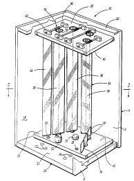
A luminaire 10 for a fluorescent light 12 according to the invention is
best shown in Figs. 1 and 2. The luminaire 10 is suitable for mounting in a
ceiling suspended or recessed in a ceiling or wall (not shown). The luminaire
10 includes a rectangular box-like body 14 having an opening for accepting a
CA 02281359 1999-09-02
conventional lite (not shown). The body 14 has a top 16 and a pair of sides 18
which extend between a pair of ends 20. The body 14 is formed of a rigid,
heat resistant material such as aluminum.
A support unit 22 is adjustably mounted to inner sides 26 of each end
20 of the body 14. Two vertically aligned rows of threaded apertures 24 are
formed in the ends 20 for receiving bolts 28 for mounting the support unit 22
to
the body 14.
As discussed more fully below, and shown in Figs. 3a and 3b, the rows
of apertures 24 permit mounting of the support unit 22 in a range of positions
to vary the width of the projected beam of light. In a raised position shown
in
Fig. 3b, the support unit 22 projects a narrow width beam 30 of light. In a
lower position, shown in Fig. 3a, the support unit 22 projects a wide width
beam 32 of light. The support unit 22 may be angled with respect to the
opening 21 for producing an asymmetric beam of light.
As shown in Fig. 2, the support unit 22 includes a pair of end pieces 40,
41 supporting the fluorescent bulb 12, a fixed center reflector 34, a pair of
fixed side reflectors 36 and two pairs of movable reflectors 38. The end
pieces
40, 41 are generally rectangular in shape having an inner edge 44, outer edge
46, and a pair of side edges 48. As discussed more fully below, the end piece
40 is spaced apart from the inner surface 26 of the housing 14 by spacer
brackets 42. The ends of the fluorescent bulb 12 are received in sockets 50
mounted on each end piece 40, 41. The bulb 12 thus extends along a
longitudinal axis within the body 14 and support member 22. An electronic
ballast 52 is also mounted on the end piece 40.
The fixed center reflector 34 is mounted by brackets to each end piece
40, 41. The center reflector 34 has two lateral sides 54 extending in a "V"
from
CA 02281359 1999-09-02
8
a corner 56. The corner 56 of the uV" is mounted between the socket 50 and
the inner edge 44 of the end pieces. The sides 54 of the center reflector 34
extend parallel with the longitudinal axis of the fluorescent bulb 12 to
reflect
light through the opening 21.
The fixed side reflectors 36 are mounted on either side of the bulb 12
adjacent the outer edge 48 of the end pieces 40, 41. In the preferred
embodiment, the fixed reflectors 36 extend along a plane which extends
parallel to the longitudinal axis of the fluorescent bulb 12 and intersects
the
outer edge 58 of each side 54 of the center reflector. The fixed reflectors 36
are made of suitable rigid material and are coated to reflect light. The
reflectors 34, 36 may be provided with any of a variety of coatings or
materials
to provide either spectral reflection or diffuse reflection. For instance,
silver
coating will provide a reflection with a minimal diffuse reflection, while a
white
enamel coating will provide a relatively low spectral reflection with a
relatively
great diffuse reflection. These types of reflection are illustrated in Figs.
13 and
14. Fig. 13 shows how light is reflected from a specular surface such as one
with a silver coating. Fig. 14 shows how light is reflected from a diffuse
surface
such as one having a white enamel coating.
As best shown in Figs. 1, 2, 4 and 4a, the movable reflectors 38 are
mounted to the end pieces by an adjustment mechanism including mounting
brackets 42 and an adjustment rod 74. The mount 62 has a shaft 66 extending
from a flange 68 for mounting the movable reflector 38. The shaft 66 is
positioned through an aperture 72 in the end piece with the flange 68
extending outwardly from the inner surface of the end piece. A gear wheel 70
is mounted on an opposite end of the rod 74 extending into the space formed
by the spacer bracket 42 between the end piece 40 and the body 14
As best shown in Fig. 4, an adjustment rod 74 having a worm gear 76 is
mounted in meshing engagement with each gear wheel 70 by the pair of
CA 02281359 1999-09-02
9
spacer brackets 42. Each adjustment rod 74 has an outer end having a head
portion 78 having a slot 80 for accepting a blade of a screwdriver for
rotating
the rod 74. The outer surface may be grooved or knurled to facilitate rotation
by hand. The worm gear 76 is positioned between a pair of cylindrical portions
82 which are received in an aperture 83 of each of the respective spacer
brackets 42. An annular flange or stop 84 is formed on the rod to abut each
bracket 42 to position the head portion 78 of the rod near the outer edge 46
of
the end piece and position the worm gear 76 in engagement with the gear 70.
A first alternative embodiment of the adjustment mechanism is shown
in Fig. 5. A rod 86 is formed with a pair of worm gears 76 to engage a pair of
gear wheels 70 to adjustment of a pair of reflectors simultaneously.
A second preferred embodiment of the adjustment mechanism is
shown in Fig. 6, in which the end pieces of the support unit are mounted
directly to the body without brackets 42. The reflectors 38 are pivotally
mounted by a mount 90 which has a flange 68 extending from a disk 92
mounted to a shaft 94 which is formed to extend through the bore 96 which is
formed through both the support unit 22 and the body 14. The end of the shaft
86 may be provided with a slot 80 as above or knurled to accept a knob 101.
A disk 98 having a collar 100 and set screw 102 is mounted to secure the
shaft 86 in position in the bore 96.
As shown in Fig. 4a, each rotating reflector 38 is rectangular and
formed of a rigid material, such as aluminum or fiberglass. It is advantageous
to proportion the width of the reflector to range between the diameter and
circumference of the lamp, for instance, between ~/2" and 4.5". The length of
the reflector 38 is approximately equal to the length of the fluorescent bulb
12.
This length can exceed 70 inches in length. At least one hole 104 is formed at
each end of the reflector 38 for receiving a screw 106 for attachment to the
flange 68 of the mount. The reflector is shown in Fig. 4 with a flat surface.
CA 02281359 1999-09-02
However, other surface shapes, such as concave or convex, can be used to
provide the desired optics. As shown in Figs. 7 and 8, a two surface reflector
110 or a three surface reflector 112 may be used. The two surface reflector
110 has a flat surface 114 and a concave surface 116. However, any other
5 shape can be provided. The surfaces may have the same shape with different
coatings. The two surface reflector 110 allows the user the option of rotating
the reflector 110 from flat surface 114 to a concave surface 116 according to
the illumination criteria used.
10 As shown in Figs. 8, 9a, 9b and 9c, the three surface reflector 112 can
be produced by combining a flat surface reflector 118 as shown in Fig. 9a, a
concave surface reflector 120 as shown in Fig. 9b, together with a convex
surface reflector 122 as shown in Fig. 9c. The reflectors are joined by
fastening angled flanges 106 together.
Although shown with two pairs of reflectors 38, three pairs or more may
be provided. The spacing between the reflector 38 permits an effective flow of
cooling air to flow through the luminaire to cool the fixture.
Referring now to Fig. 10, a second preferred embodiment of the
present invention is shown. fn this embodiment, the invention comprises a
reflector assembly 200 which is designed to reflect light from a bulb 212 in a
luminaire 210. This embodiment differs from the earlier embodiment in that the
bulb 212 is directly supported by the luminaire 210 rather than by the
reflector
assembly 200. The reflector assembly 200 of this embodiment can therefore
be retrofit to an existing luminaire without modifying the bulb mounting
wiring
and position. Alternatively, the reflector assembly 200 can be used as part of
a
new luminaire.
CA 02281359 1999-09-02
I1
The luminaire 210 has a body 214 made up of a top 216 and a pair of
sides 218 which extend between a first end 220 and a second end 221 of the
luminaire 210. The sides 218 define an opening 222 for permitting a beam of
light to be emitted. The light emitted from the luminaire is made up of two
parts, a direct light beam and a reflected light beam. The direct light beam
is
formed by the light which radiates directly from the bulb 212 out through the
opening 222. The bulb 212 radiates in other directions as well and it is the
function of the reflector assembly 200 to reflect this light back through the
opening 222 as a reflected light beam. The luminaire 210 supports the bulb
212 in the body 214 between the opening 222 and the top 216. The second
end 221 of the luminaire 210 has been removed in Fig. 10 to more clearly
illustrate the invention.
The reflector assembly 200 includes a reflector support unit 224 which
includes a first end 226 and a second end 228. The reflector support unit 224
is configured to be mounted within the body 214 of the luminaire 210 between
the opening 222 and the top 216. When installed in the luminaire body 214,
the first end 226 of the reflector support unit 224 is adjacent the first end
220
of the luminaire body 214 and the second end 228 of the reflector support unit
224 is adjacent the second end 221 of the luminaire body 214. The ends 226
and 228 of the support unit 224 are designed to be interconnected with the
adjacent ends 220 and 221 of the luminaire body 214, so that each end 226
and 228 of the reflector support unit 224 is independently, vertically
adjustable
in a linear direction so as to adjust the distance between each end, 226 and
228, of the support unit 224 and the opening 222 of the luminaire body 214.
By adjusting the distance between the reflector support unit 224 and the
opening 222 of the luminaire body 214, the shape of the reflected light beam
emitted from the luminaire 210 cam be adjusted as was shown in Figs. 3a and
3b. In this embodiment, the direct light beam projecting downward from the
bulb 212 will not be affected by repositioning the reflector support unit 224.
However, the reflected light beam from the reflector assembly 200 will be
affected by repositioning the reflector support unit 224 being interconnected
CA 02281359 1999-09-02
12
with the first end 220 of the luminaire body 214 using bolts 28 which engage
threaded apertures 24. A plurality of threaded apertures 24 may be provided
in the ends 220 and 221 of the luminaire body 214 to allow for adjustment in
the position of the reflector assembly 200.
An alternative approach is shown with the second end 228 of the
support end 224. On this end, support brackets 229 are shown attached to the
second end 228 of the support unit 224. The support brackets 229 can serve a
variety of functions. First, the support brackets 229 support the second end
228 in an offset position from the second end 221 of the luminaire body 214
so as to provide clearance for an adjustment mechanism, such as the one
discussed below. Secondly, the support brackets 229 provide a means to
interconnect the end 221 of the luminaire body 214 with the end 228 of the
support unit 224. Depending on the application, especially where a retrofit is
contemplated, it may be necessary to adapt the luminaire body 214 so that the
reflector assembly 200 can be supported therein. Support brackets 229 of
various sizes and shapes can be used to adapt the luminaire body 214. The
support brackets 229 would first be mounted to the inside of the end 221 of
the luminaire body 214 using screws or bolts or other connection means. The
brackets 229 would then provide a variety of attachment points for
interconnection with the end 228 of the support unit 224 thereby allowing
adjustment in the position of the connector assembly 200.
Other interconnection means are also possible. For example, rivets
may be used to interconnect the ends 226 or 228 of the support unit 224 with
the ends 220 or 221 of the luminaire body where easy adjustment of the
position of the reflector assembly 200 is not required. This would simply
require drilling a hole through the end 226 or 228 of the support unit 224 and
through the end 220 or 221 of the luminaire body 214 and using a rivet to
interconnect the two holes. Rivets could also be used to connect a bracket
229 to either the luminaire body 214 or the support unit 224. Alternatively,
support unit 224 may include tabs which extend outwardly from the ends 226
CA 02281359 1999-09-02
13
and 228. The luminaire body 214 may include holes, or holes may be added,
so that the tabs on the support unit 224 may engage the holes in the body 214
of the luminaire 210. Yet other interconnection means are also possible as
will
be clear to tone of skill in the art. This includes gluing or welding the
support
unit 224 to the body 214 or ultrasonically welding the two together if they
are
plastic.
The reflector assembly 200 also includes one or more reflectors. In the
illustrated embodiment, the reflector assembly 200 includes a fixed center
l0 reflector 230 positioned directly above the bulb 212. For purposes of
description, a central plane is defined as longitudinally bisecting the
support
unit 224 such that it passes through the opening 222 of the luminaire body
214 when the support unit 224 is mounted within the luminaire body 214. The
central plane longitudinally bisects the reflector support unit 224 such that
the
longitudinal axis of the bulb 212 and the longitudinal axis of the fixed
center
reflector 230 are contained within the central plane. Using the central plane
as
a reference, three reflectors are positioned on each side of the central
plane.
On one side of the central plane is a first reflector 232, a third reflector
236
and a fifth reflector 240. On the other side of the central plane, and
symmetrical with the other three reflectors, 232, 236 and 240, are a second
reflector 234, a fourth reflector 238, and a sixth reflector 242.
Alternatively, the
reflector assembly 200 may include fewer or a greater number of reflectors.
Also, the reflectors may have two or more sides as shown in Figs. 7 and 8.
The reflectors may have either a specular or diffuse surface and may be flat,
concave, or convex depending on the application.
Like in the earlier described embodiments, the reflectors 232-242 are
pivotally mounted to the support unit 224 such that each reflector can pivot
with respect to the support unit about its own longitudinal axis. Further, the
reflectors 232-242 are preferably detachably mounted to the reflector support
unit. A preferred approach for interconnecting reflectors and the reflector
support assembly 224 was discussed earlier and shown in Fig. 4a.
CA 02281359 1999-09-02
14
Referring back to Figs. 4a and 6, details of one preferred approach to
supporting the reflectors 232-242 is illustrated. Each end of the reflectors
are
mounted to a mount 62. The mount 62 includes a flange 68 for mounting an
end of a reflector. The reflectors have holes 104 which align with holes in
the
flange 68 and accept screws 106 for holding the reflectors to the mount 62.
The mount 62 also includes a shaft 66 extending from the flange 68. Referring
also to Fig. 10, the shafts 66 of the mounts 62 pass through holes in the ends
226 and 228 of the reflector support unit 224. In this way, the reflectors 232-
242 are supported for pivotal movement. Adjustment gear wheels are
mounted to the mount 62 at the end of the shafts 66 opposite the flanges 68 at
one end of the reflectors 232-242. In this way, the position of each
adjustment
gear wheel determines the pivotal position of each reflector.
Several different adjustment mechanisms are envisioned with the ones
illustrated in Figs. 10, 11, and 12 being preferred. As discussed above,
adjustment gear wheels are interconnected with the reflectors 232-242 by the
mounts 62. A first adjustment gear wheel 224 controls the first reflector 232,
a
second adjustment gear wheel 246 controls the second reflector 234, a third
adjustment gear wheel 248 controls the third reflector 236, a fourth
adjustment
hear wheel 250 controls a fourth reflector 238, a fifth adjustment gear wheel
252 controls the fifth reflector 240, and a sixth adjustment gear wheel 254
controls the sixth reflector 242. The adjustment mechanism also includes
coordinating gears which mesh with and interconnect the adjustment gear
wheels so that the adjustment gear wheels and the reflectors move in a
coordinated manner. A first coordinating gear 256 is positioned adjacent and
engages both the first and the third adjustment gear wheels 244 and 248 so
that the first coordinating gear 256 and the first and third adjustment gear
wheels, 244 and 248, rotate together. Likewise, a second coordinating gear
258 is positioned adjacent and engages both the third adjustment gear wheel
248 and the fifth adjustment gear wheel 252. A third coordinating gear wheel
260 and a fourth coordinating gear wheel 262 likewise engage the adjustment
CA 02281359 1999-09-02
gear wheels 246, 250, 254 on the other side of the luminaire thereby
coordinating their movement.
As shown, the adjustment gear wheels 244-254 are each identical in
5 size to each other. The coordinating gears 256-262 are also identical in
size to
each other but are smaller in size than the adjustment gear wheels 244-254.
With this configuration, the first, third and fifth, 232, 236, 240, reflectors
all
rotate an identical amount when any one of them is turned. Alternatively, the
sizes of the adjustment gear wheels 244-254 and the coordinating gears 256-
10 262 may be adjusted so that various reflectors turn by different amount. It
is
desired that the gear sizes be chosen such that the reflectors nearest the
bulb
rotate less than the reflectors further from the bulb. In one preferred
arrangement, for a given amount of adjustment, the reflector nearest the bulb
rotates half the amount of the reflector second from the bulb which in turn
15 rotates half as much as the reflector furthest from the bulb. For example,
for a
given adjustment of drive gear 266, reflector 232 will rotate 5 degrees,
reflector 236 will rotate 10 degrees, and reflector 240 will rotate 20
degrees.
The actual ratios of the gear sizes will depend upon the desired reflection
pattern and the application of the luminaire. The variation in rotation ratios
for
a given adjustment can be achieved in several ways as will be clear to one of
skill in the art. For example, the adjustment gear wheels 244-254 may be of
different diameters so as to achieve different amounts of rotation for the
various reflectors. One particularly preferred embodiment of this approach is
illustrated in Fig. 21. This figure adopts the numbering as used on the
coordinating gears and adjustment gears on the left half of the luminaire 210
in Fig. 10. However, for ease of illustration, the gears are arranged in a
straight line. Depending on packaging constraints, the gears may be moved
out of the straight line configuration. In Fig. 21, a knob gear 276 is
connected
to an adjustment knob (not shown) and has twelve teeth. Knob gear 276
drives the drive gear 264 which has ten teeth. It in turn drives the sixth
adjustment gear wheel 254 having twenty teeth which in turn drives the fourth
coordinating gear 262 having ten teeth, which drives the fourth adjustment
CA 02281359 1999-09-02
16
gear wheel 250 having twelve teeth, which in turn drives the third
coordinating
gear 260 having ten teeth, which in turn drives the second adjustment gear
wheel 246 having ten teeth. Obviously, reflectors attached to the adjustment
gear wheels 254, 250, 246 rotate by differing amounts when the knob gear
276 is rotated. By varying the diameter and number of teeth on the adjustment
gear wheels 254, 250, 246, the rotation ratios may be selected. Alternatively,
the coordinating gears may have different gear ratios on each of their sides
so
that the adjustment gear wheels which mesh with the coordinating gear turn
by different amounts depending on which side of the coordinating gear
l0 engages them. This may be achieved by forming the coordinating gear as two
half gears of different diameters as shown in Fig. 22. In Fig. 22, a left
adjustment gear wheel 280 and a right adjustment gear wheel 282 both mesh
with an intermediate coordinating gear 284 positioned therebetween. As
shown, the intermediate coordinating gear 284 as if the intermediate
coordinating gear 284 is formed with pieces of a large diameter gear and a
small diameter gear. The intermediate coordinating gear 284 is arranged such
that the large diameter portion 286 meshes with the left adjustment gear
wheel 280 while the small diameter portion 288 meshes with the right
adjustment gear wheel 282. Therefore, for a given rotation of the left
adjustment gear wheel 280, the right adjustment gear wheel 282 rotates by a
lesser amount but in the same direction as the left adjustment gear wheel 280.
Alternatively, the coordinating gears may be made up of a pair of stacked
gears with one of the stacked gears engaging one adjustment gear wheel and
the other stacked gear engaging the other adjustment gear wheel. Obviously,
these various approaches to varying the rotation ratios may also be combined
to provide further flexibility.
Also shown in Figs. 10 and 11, are drive gears 264 and 266 which
engage the outermost adjustment gear wheels 252 and 254 respectively.
These drive gears are used to adjust the entire adjustment mechanism. For
example, the drive gears 264 and 266 may be accessed from below the
luminaire 210 and rotated thereby adjusting the position of the reflectors 232-
CA 02281359 1999-09-02
1~
242. The drive gears 264 and 266 are each connected to a knob 265, 267
similar to the one shown in Fig. 6 at 101. A shaft extends from each of the
drive gears 264, 266 through the end 228 of the support unit 224 and each
has the knob 265, 267 mounted on the inside of the second end 228 of the
support unit 224. This allows adjustment of the position of the reflectors 232-
242 from inside the luminaire opening 222. A spring may be positioned under
the knob to lock the mechanism to avoid movement. Other locking means may
also be used.
Referring now to Fig. 12, the worm drive adjuster 268 is substituted for
the drive gears 264 and 266. The worm drive adjuster comprises a vertical
shaft 270 with a knob 272 on one end and a worm drive gear 274 on its other
end. The worm drive gear 274 engages adjustment gear wheel 254 so that the
position of the reflectors may be adjusted by rotating knob 272. A second
worm drive adjuster may be included on the other side of the reflector support
unit to adjust the reflectors on the other side of the reflector support unit
to
adjust the reflectors on the other side or additional gears may be added so as
to interconnect the adjustment gear wheels on each side of the reflector
support unit. Alternatively, a longer shaft with several worm drive gears may
be used to engage several adjustment gear wheels similar to the approach
shown in Fig. 5. As will be clear to one of skill in the art, many other
variations
on the adjustment mechanism are possible. For example, the adjustment gear
wheels may include stops which prevent their rotation beyond a certain
position so that the end user of the reflector assembly 200 cannot adjust the
reflectors beyond their operating range.
Referring now to Figs. 15 and 16, the effect of reflector positioning is
illustrated. In Fig. 15, light is shown radiating from a fluorescent bulb 212
and
being reflected from the first, third, and fifth reflectors, 232, 236, 240.
The
reflectors each have their longitudinal axis located in a plane A which is
defined as a first reflector plane. The central plane, discussed earlier, is
shown as a vertical line containing the longitudinal axis of the fluorescent
bulb
CA 02281359 1999-09-02
18
212 and is marked as B. The first reflector plane and the central plane B
intersect to define a line which is parallel to the longitudinal axes of the
reflectors 232, 236 and 240. The angle formed between the central plane B
and the first reflector plane A is defined as a first mounting angle and is
illustrated in Fig. 15 as 6~. Referring now to Fig. 16, the reflectors 232,
236
and 240 are once again shown reflecting light emanating from the fluorescent
bulb 212. However, in this case, the first reflector plane A is repositioned
so
that first mounting angle 62 is much larger than first mounting angle 6~ in
Fig.
15. As shown in the figures, the direction and the width of reflected beams
are
l0 changed. Beam C in Fig. 15 and beam D in Fig. 16 illustrate only that
portion
of the reflected light beam which is reflected from the fifth reflector 240.
In Fig.
15, with a narrow first mounting angle 8,, the reflected beam C is narrow and
reflected almost vertically so that it will illuminate an area near to the
central
plane B. In Fig. 16, the light beam D reflected from the reflector 240
positioned
at a wide first mounting angle 62 is wider than the beam C and is directed
outwardly away from the central plane B. By changing the mounting angle of
the reflector assembly of the present invention, the total width of the
reflected
beams from the reflector assembly can be limited or expanded.
It should be noted that reflector 240 is positioned such that the
reflective surface lies in the first reflector plane A and it is assumed that
a flat
reflective surface is used. If the reflector 240 were rotated
counterclockwise, it
would no longer intercept as much light from the bulb with some light passing
behind the reflector and not being reflected through the opening. Therefore,
the position shown for reflector 240 is the furthest counterclockwise position
for efficient reflection of light. Also, the distance of beam C from the
central
plane B is the furthest from the central plane B that light can be reflected
using
a flat reflective surface lying in the reflector plane A.
As can be seen , the first mounting angle A~ or 62 controls how wide a
beam of light can be reflected from the reflector located on the first
reflector
CA 02281359 1999-09-02
19
plane. Therefore, a reflector assembly with a narrow mounting angle such as
6~ in Fig. 15 would be limited in how wide of a reflected beam C it can
create.
A reflector assembly with a wide mounting angle such as 62 in Fig. 16 will be
able to reflect light in a much wider beam and much further from the central
plane B. Depending on the application, different mounting angles are
desirable as will be clear to one of skill in the art. Generally, the mounting
angle should not be less that 20 degrees or greater that 90 degrees. Also, the
reflectors 234, 238, and 242 on the other side of the central plane B are
preferably positioned in a second reflector plane which intersects the central
to plane at a second mounting angle. This second mounting angle may be the
same as the first mounting angle or a different angle depending on the
application.
Referring now to Figs. 17-20, a variety of light reflection patterns are
shown indicating a variety of patterns which can be created by repositioning
the six reflectors 232-242 in the reflector assembly. In Fig. 17, the
reflectors
232-242 are positioned such that the reflected beam created by each of the
six reflectors is focused on the area directly below the bulb 212. The light
reflected from each of the six reflectors also overlaps. This greatly
increases
the amount of light available in the area directly below the bulb 212.
Depending on the configuration, the illumination reflected from each of the
reflectors 232-242 is approximately equal to the illumination created by the
light radiating directly from the bulb 212. Therefore, by focusing beams
created by each of the reflectors 232-242 on the area below the bulb 212, the
illumination available directly below the bulb 212 is substantially increased.
The pattern created by the reflectors shown in Fig. 17 is called a center
weighted, focused distribution of light and is particularly useful where a
great
deal of illumination is needed in a small area.
In Fig. 18, the reflectors 232-242 are shown positioned such that the
reflected beams of light are more spread out than they were for the position
CA 02281359 1999-09-02
shown in Fig. 17. Once again, the reflected light beams overlap. In this case
they are more spread out to form a wider area of increased illumination. This
pattern is called a laterally centered distribution of light and is
particularly
useful where increased illumination is needed in a somewhat larger area than
5 is required for the pattern shown in Fig. 17.
Fig. 19 shows the reflectors 232-242 positioned such that reflected
beams of light are spread out much wider than previously illustrated and the
reflected light beams do not significantly overlap. This is a pattern that
would
l0 be created with the reflective surfaces of the reflectors 232-242 on each
side
of the bulb 212 positioned in planes much as was shown in Figs. 15 and 16.
As can be seen, the reflected beams do not illuminate the area directly below
the bulb 212. This pattern is called a fanned distribution of light and may be
useful where a very wide distribution of light is desired or where the area
15 directly below the bulb 212 does not require additional illumination.
Fig. 20 shows reflectors 232-242 positioned such that the reflected
beams of light are spread even more widely than the pattern shown in Fig. 19.
As explained earlier, this positioning allows some light to escape
interception
20 by the reflectors and pass behind them. However, this pattern allows for a
very wide distribution of light. Depending on the positioning of the
individual
reflectors, the reflected light beams may overlap so as to create areas of
more
intense illumination. This pattern is called a laterally fanned distribution
of light
and is particularly useful where the area below the bulb 212 does not require
additional illumination such as if a luminaire is positioned directly above a
partition wall.
As will be clear to one of skill in the art, other light patterns may be
created by repositioning the reflectors. Also, the above discussed patterns
may be created by repositioning the reflectors. Also, the above discussed
patterns may be combined such that reflectors on one side of the bulb 212
CA 02281359 1999-09-02
21
focus light beneath the bulb while the reflectors on the other side of the
bulb
reflect light away from the location beneath the bulb 212. This may be
desirable where the illumination needs are not symmetrical with respect to a
luminaire. It should also be noted that the patterns shown in Figs. 17-20 do
not illustrate the light beam directly emitted from the bulb, earlier defined
as a
direct light beam. The illustrated reflected light beams serve to reinforce
the
illumination provided by the direct light beam. Therefore, while the direct
light
beam will tend to provide a uniform level of illumination, the reflected light
beams can be used to provide areas of increased illumination where needed.
While there have been described what are present to be the preferred
embodiments of the invention, it will be understood that various modifications
may be made therein and the invention is intended to cover in the
independent claims all such modifications as fall within the true spirit and
scope of the invention.