Note: Descriptions are shown in the official language in which they were submitted.
CA 02281429 1999-09-03
,
" INTEGRATED HYDROTREATING AND
HYDROCRACKING PROCESS
BACKGROUND
Petroleum refiners often produce desirable products such as
turbine fuel, diesel fuel and other products known as middle distillates as
well as
lower boiling hydrocarbonaceous liquids such as naphtha and gasoline by
hydrocracking a hydrocarbon feedstock derived from crude oil, for example.
Feedstocks most often subjected to hydrocracking are gas oils and heavy gas
oils recovered from crude oil by distillation. A typical heavy gas oil
comprises a
substantial portion of hydrocarbon components boiling above 371 C (700 F),
usually at least about 50 percent by weight. A typical vacuum gas oil normally
has a boiling point range between 315 to 565"C (600 to 1050 F).
Hydrocracking is generally accomplished by contacting in a
hydrocracking reaction vessel or zone the gas oil or other feedstock to be
treated with a suitable hydrocracking catalyst under conditions of elevated
temperature and pressure in the presence of hydrogen so as to yield a product
containing a distribution of hydrocarbon products desired by the refiner. The
operating conditions and the hydrocracking catalysts within a hydrocracking
reactor influence the yield of the hydrocracked products.
Although a wide variety of process flow schemes, operating
conditions and catalysts have been used in commercial activities, there is
Docket No. 103162 1
CA 02281429 1999-09-03
always a demand for new hydrocracking methods which provide lower costs and
higher liquid product yields. It is generally known that enhanced product
selectivity can be achieved at lower conversion per pass (60% to 90%
conversion of fresh feed) through the catalytic hydrocracking zone. However,
it
was previously believed that any advantage of operating at below about 60%
conversion per pass was negligible or would only see diminishing returns. Low
conversion per pass is generally more expensive, however, the present
invention greatly improves the economic benefits of a low conversion per pass
process and demonstrates the unexpected advantages.
SUMMARY
The present invention is a catalytic hydrocracking process which
provides higher liquid product yields, specifically higher yields of turbine
fuel and
diesel oil. The process of the present invention provides the yield advantages
associated with a low conversion per pass operation without compromising unit
economics. Other benefits of a low conversion per pass operation include the
elimination of the need for inter-bed hydrogen quench and the minimization of
the fresh feed pre-heat since the higher flow rate of recycle liquid will
provide
additional process heat to initiate the catalytic reaction and an additional
heat
sink to absorb the heat of reaction. An overall reduction in fuel gas and
2o hydrogen consumption and light ends production may also be obtained.
Finally,
the low conversion per pass operation requires less catalyst volume.
Docket No. 103162 2
CA 02281429 1999-09-03
In one embodiment the present invention relates to a process for
hydrocracking a hydrocarbonaceous feedstock which process comprises the
steps of: (a) passing a hydrocarbonaceous feedstock and hydrogen to a
catalytic denitrification and desulfurization reaction zone at reaction
conditions
including a temperature from 204 to 482 C (400 to 900 F), a pressure from 3.5
to 17.3 mPa (500 to 2500 psig), a liquid hourly space velocity of the
hydrocarbonaceous feedstock from 0.1 to 10 hr', with a catalyst; and
recovering a denitrification and desulfurization reaction zone effluent
therefrom;
(b) passing the effluent directly to a hot, high pressure stripper utilizing a
hot,
lo hydrogen-rich stripping gas to produce a first vapor stream comprising
hydrogen, hydrocarbonaceous compounds boiling at a temperature below the
boiling range of the hydrocarbonaceous feedstock, hydrogen sulfide and
ammonia, and a first liquid stream comprising hydrocarbonaceous compounds
boiling in the range of the hydrocarbonaceous feedstock; (c) passing at least
a
portion of the first liquid stream to a hydrocracking zone containing a
hydrocracking catalyst and operating at a temperature of 204 to 482 C (400 to
about 900 F), a pressure from 3.5 to 17.3 mPa (500 to 2500 psig), a liquid
hourly space velocity from 0.1 to 15 hr 1; and recovering a hydrocracking zone
effluent therefrom; (d) passing the hydrocracking zone effluent to the
2o denitrification and desulfurization reaction zone; (e) condensing at least
a
portion of the first vapor stream recovered in step (b) to produce a second
liquid
stream comprising hydrocarbonaceous compounds boiling at a temperature
below the boiling range of the hydrocarbonaceous feedstock and a second
Docket No. 103162 3
CA 02281429 1999-09-03
vapor stream comprising hydrogen and hydrogen sulfide; and (f) recycling at
least a portion of the second vapor stream to the hydrocracking zone.
In a second embodiment, the present invention relates to a
process for hydrocracking a hydrocarbonaceous feedstock as described above
in the first embodiment wherein at least a second portion of the second vapor
stream is embodied into a reflux heat exchange zone located in an upper end of
the stripper to produce reflux; and the second portion of the second vapor
stream is removed from the reflux heat exchange zone and is introduced into a
lower end of the stripper to supply stripping medium.
In a third embodiment the present invention relates to a process
for hydrocracking a hydrocarbonaceous feedstock as described in the first
embodiment wherein at least a portion of the first vapor stream recovered in
step (b) is passed to a post-treat hydrogenation reaction zone to saturate
aromatic compounds; and at least a portion of the resulting effluent from the
post-treat hydrogenation reaction zone is condensed to produce at least a
portion of the second liquid stream comprising hydrocarbonaceous compounds
boiling at a temperature below the boiling range of the hydrocarbonaceous
feedstock and at least a portion of the second vapor stream comprising
hydrogen and hydrogen sulfide.
Further in a fourth embodiment the present invention relates to a
process for hydrocracking a hydrocarbonaceous feedstock which process
comprises the steps of: (a) passing a hydrocarbonaceous feedstock and
Docket No. 103162 4
CA 02281429 1999-09-03
hydrogen to a denitrification and desulfurization catalytic reaction zone at
reaction zone conditions including a temperature from 204 to 482 C (400 to
900 F), a pressure from 3.5 to 17.3 mPa (500 to 2500 psig), a liquid hourly
space velocity of the hydrocarbonaceous feedstock from 0.1 to 10 hr', and
recovering a denitrification and desulfurization reaction zone effluent
therefrom;
(b) passing the effluent directly to a hot, high pressure stripper utilizing a
hot,
hydrogen-rich stripping gas to produce a first vapor stream comprising
hydrogen, hydrocarbonaceous compounds boiling at a temperature below the
boiling range of the hydrocarbonaceous feedstock, hydrogen sulfide and
1o ammonia, and a first liquid stream comprising hydrocarbonaceous compounds
boiling in the range of the hydrocarbonaceous feedstock; (c) passing at least
a
portion of the first liquid stream to a hydrocracking zone containing a
hydrocracking catalyst and operating at a temperature of 204 to 482 C (400 to
900 F), a pressure from 3.5 to 17.3 mPa (500 to 2500 psig), a liquid hourly
space velocity from 0.1 to 15 hr'; and recovering a hydrocracking zone
effluent
therefrom; (d) passing the hydrocracking zone effluent to the denitrification
and
desulfurization reaction zone; (e) passing at least a portion of the first
vapor
stream recovered in step (b) to a post-treat hydrogenation reaction zone to
saturate aromatic compounds; (f) condensing at least a portion of the
resulting
2o effluent from the post-treat hydrogenation reaction zone to produce a
second
liquid stream comprising hydrocarbonaceous compounds boiling at a
temperature below the boiling range of the hydrocarbonaceous feedstock and a
second vapor stream comprising hydrogen and hydrogen sulfide; (g) recycling at
Docket No. 103162 5
CA 02281429 1999-09-03
least a first portion of the second vapor stream to the hydrocracking zone;
(h) introducing at least a second portion of the second vapor stream into a
reflux
heat exchanger located in an upper end of the stripper to produce reflux; and
(i) removing and heating the second portion of the second vapor stream from
the reflux heat exchange zone and introducing the second portion of the second
vapor stream into a lower end of the stripper to supply a stripping medium.
BRIEF DESCRIPTION OF THE DRAWING
The drawing is a simplified process flow diagram of a preferred
embodiment of the present invention.
DETAILED DESCRIPTION
It has been discovered that higher liquid product yields and a
lower cost of production can be achieved and enjoyed in the above-described
integrated hydrotreating and hydrocracking process.
The process of the present invention is particularly useful for
hydrocracking a hydrocarbon oil containing hydrocarbons and/or other organic
materials to produce a product containing hydrocarbons and/or other organic
materials of lower average boiling point and lower average molecular weight.
The hydrocarbon feedstocks that may be subjected to hydrocracking by the
method of the invention include all mineral oils and synthetic oils (e.g.,
shale oil,
tar sand products, etc.) and fractions thereof. Illustrative hydrocarbon
feedstocks include those containing components boiling above 288 C (550 F),
Docket No. 103162 6
CA 02281429 1999-09-03
such as atmospheric gas oils, vacuum gas oils, deasphalted, vacuum, and
atmospheric residua, hydrotreated or mildly hydrocracked residual oils, coker
distillates, straight run distillates, solvent-deasphalted oils, pyrolysis-
derived oils,
high boiling synthetic oils, cycle oils and cat cracker distilllates. A
preferred
hydrocracking feedstock is a gas oil or other hydrocarbon fraction having at
least 50% by weight, and most usually at least 75% by weight, of its
components boiling at temperatures above the end point of the desired product,
which end point, in the case of heavy gasoline, is generally in the range from
193 to 216 C (380 to 420 F). One of the most preferred gas oil feedstocks will
1o contain hydrocarbon components which boil above 288 C with best results
being achieved with feeds containing at least 25 percent by volume of the
components boiling between 316 to 538 C (600 and 1000 F) an especially
preferred feedstock boils in the range of 232 to 566 C (450 to 1050 F).
Also included are petroleum distillates wherein at least 90 percent
of the components boil in the range from 149 to 427 C (300 to 800 F). The
petroleum distillates may be treated to produce both light gasoline fractions
(boiling range, for example, from 10 to 85 C (50 to 185 F) and heavy gasoline
fractions (boiling range, for example, from 85 to 204 C (185 to 400 F). The
present invention is particularly suited for maximizing the yield of liquid
products
including middle distillate products.
The selected feedstock is first introduced into a catalytic
denitrification and desulfurization reaction zone together with a hot
Docket No. 103162 7
CA 02281429 1999-09-03
hydrocracking zone effluent at hydrotreating reaction conditions. Preferred
denitrification and desulfurization reaction conditions or hydrotreating
reaction
conditions include a temperature from 204 to 482 C (400 to about 900 F), a
pressure from 3.5 to 17.3 mPa (500 to 2500 psig), a liquid hourly space
velocity
of the fresh hydrocarbonaceous feedstock from 0.1 to 10 hr' with a
hydrotreating catalyst or a combination of hydrotreating catalysts.
The term "hydrotreating" as used herein refers to processes
wherein a hydrogen-containing treat gas is used in the presence of suitable
catalysts which are primarily active for the removal of heteroatoms, such as
sulfur and nitrogen and for some hydrogenation of aromatics. Suitable
hydrotreating catalysts for use in the present invention are any known
conventional hydrotreating catalysts and include those which are comprised of
at least one Group VIII metal, preferably iron, cobalt and nickel, more
preferably
cobalt and/or nickel and at least one Group VI metal, preferably molybdenum
and tungsten, on a high surface area support material, preferably alumina.
Other suitable hydrotreating catalysts include zeolitic catalysts, as well as
noble
metal catalysts where the noble metal is selected from palladium and platinum.
It is within the scope of the present invention that more than one type of
hydrotreating catalyst be used in the same reaction vessel. The Group VIII
metal is typically present in an amount ranging from 2 to 20 wt.%, preferably
from 4 to 12 wt.%. The Group VI metal will typically be present in an amount
ranging from 1 to 25 wt. %, preferably from 2 to 25 wt.%.
Docket No. 103162 8
CA 02281429 1999-09-03
The resulting effluent from the denitrification and desulfurization
reaction zone is transferred without intentional heat-exchange (uncooled) and
is
introduced into a hot, high pressure stripping zone maintained at essentially
the
same pressure as the denitrification and desulfurization reaction zone where
it
is countercurrently stripped with a hydrogen-rich gaseous stream to produce a
first gaseous hydrocarbonaceous stream containing hydrocarbonaceous
compounds boiling at a temperature less than 371 C (700 F), hydrogen sulfide
and ammonia, and a first liquid hydrocarbonaceous stream containing
hydrocarbonaceous compounds boiling at a temperature greater than 371 C.
1 o The stripping zone is preferably maintained at a temperature in the range
from
232 to 468 C (450 to about 875 F). The effluent from the denitrification and
desulfurization reaction zone is not substantially cooled prior to stripping
and
would only be lower in temperature due to unavoidable heat loss during
transport from the reaction zone to the stripping zone. It is preferred that
any
cooling of the denitrification and desulfurization reaction zone effluent
prior to
stripping is less than 56 C (100 F). By maintaining the pressure of the
stripping
zone at essentially the same pressure as the denitrification and
desulfurization
reaction zone is meant that any difference in pressure is due to the pressure
drop required to flow the effluent stream from the reaction zone to the
stripping
zone. It is preferred that the pressure drop is less than 690 kPa (100 psig).
The
hydrogen-rich gaseous stream is preferably supplied to the stripping zone in
an
amount greater than about 1 wt.% of the hydrocarbonaceous feed to this zone.
In one embodiment, the hydrogen-rich gaseous stream used as the stripping
Docket No. 103162 9
CA 02281429 1999-09-03
medium in the stripping zone is first introduced into a reflux heat exchange
zone
located in an upper end of the stripping zone to produce reflux therefor and
then
introducing the resulting heated hydrogen-rich gaseous stream into a lower end
of the stripping zone to perform the stripping function.
At least a portion of the first liquid hydrocarbonaceous stream
containing hydrocarbonaceous compounds boiling at a temperature greater
than 371 C (700 F) recovered from the stripping zone is introduced directly
into
a hydrocracking zone along with added hydrogen. The hydrocracking zone may
contain one or more beds of the same or different catalyst. In one embodiment,
1 o when the preferred products are middle distillates, the preferred
hydrocracking
catalysts utilize amorphous bases or low-level zeolite bases combined with one
or more Group VIII or Group VIB metal hydrogenating components. In another
embodiment, when the preferred products are in the gasoline boiling range, the
hydrocracking zone contains a catalyst which comprises, in general, any
crystalline zeolite cracking base upon which is deposited a minor proportion
of a
Group VIII metal hydrogenating component. Additional hydrogenating
components may be selected from Group VIB for incorporation with the zeolite
base. The zeolite cracking bases are sometimes referred to in the art as
molecular sieves and are usually composed of silica, alumina and one or more
2o exchangeable cations such as sodium, magnesium, calcium, rare earth metals,
etc. They are further characterized by crystal pores of relatively uniform
diameter between 4 and 14 Angstroms (10-10 meters). It is preferred to employ
Docket No. 103162 10
CA 02281429 1999-09-03
zeolites having a relatively high silica/alumina mole ratio between 3 to 12.
Suitable zeolites found in nature include, for example, mordenite, stilbite,
heulandite, ferrierite, dachiardite, chabazite, erionite and faujasite.
Suitable
synthetic zeolites include, for example, the B, X, Y and L crystal types,
e.g.,
synthetic faujasite and mordenite. The preferred zeolites are those having
crystal pore diameters between 8-12 Angstroms (10-10 meters), wherein the
silica/alumina mole ratio is 4 to 6. A prime example of a zeolite falling in
the
preferred group is synthetic Y molecular sieve.
The natural occurring zeolites are normally found in a sodium
1 o form, an alkaline earth metal form, or mixed forms. The synthetic zeolites
are
nearly always prepared first in the sodium form. In any case, for use as a
cracking base it is preferred that most or all of the original zeolitic
monovalent
metals be ion-exchanged with a polyvalent metal and/or with an ammonium salt
followed by heating to decompose the ammonium ions associated with the
zeolite, leaving in their place hydrogen ions and/or exchange sites which have
actually been decationized by further removal of water. Hydrogen or
"decationized" Y zeolites of this nature are more particularly described in US-
A-
3,130,006.
Mixed polyvalent metal-hydrogen zeolites may be prepared by ion-
2o exchanging first with an ammonium salt, then partially back exchanging with
a
polyvalent metal salt and then calcining. In some cases, as in the case of
synthetic mordenite, the hydrogen forms can be prepared by direct acid
Docket No. 103162 11
CA 02281429 1999-09-03
treatment of the alkali metal zeolites. The preferred cracking bases are those
which are at least 10%, and preferably at least 20%, metal-cation-deficient,
based on the initial ion-exchange capacity. A specifically desirable and
stable
class of zeolites are those wherein at least about 20% of the ion exchange
capacity is satisfied by hydrogen ions.
The active metals employed in the preferred hydrocracking
catalysts of the present invention as hydrogenation components are those of
Group VIII, i.e., iron, cobalt, nickel, ruthenium, rhodium, palladium, osmium,
iridium and platinum. In addition to these metals, other promoters may also be
1o employed in conjunction therewith, including the metals of Group VIB, e.g.,
molybdenum and tungsten. The amount of hydrogenating metal in the catalyst
can vary within wide ranges. Broadly speaking, any amount between 0.05% to
30 wt.% may be used. In the case of the noble metals, it is normally preferred
to use 0.05 to 2 wt.%. The preferred method for incorporating the
hydrogenating metal is to contact the zeolite base material with an aqueous
solution of a suitable compound of the desired metal wherein the metal is
present in a cationic form. Following addition of the selected hydrogenating
metal or metals, the resulting catalyst powder is then filtered, dried,
pelleted with
added lubricants, binders or the like if desired, and calcined in air at
temperatures of, e.g., 371 -648 C (700-1200 F) in order to activate the
catalyst
and decompose ammonium ions. Alternatively, the zeolite component may first
be pelleted, followed by the addition of the hydrogenating component and
activation by calcining. The foregoing catalysts may be employed in undiluted
Docket No. 103162 12
CA 02281429 1999-09-03
form, or the powdered zeolite catalyst may be mixed and copelleted with other
relatively less active catalysts, diluents or binders such as alumina, silica
gel,
silica-alumina cogels, activated clays and the like in proportions ranging
between 5 to 90 wt.%. These diluents may be employed as such or they may
contain a minor proportion of an added hydrogenating metal such as a Group
VIB and/or Group VIII metal.
Additional metal promoted hydrocracking catalysts may also be
utilized in the process of the present invention which comprises, for example,
aluminophosphate molecular sieves, crystalline chromosilicates and other
1o crystalline silicates. Crystalline chromosilicates are more fully described
in US-
A-4,363,718.
The hydrocracking of the hydrocarbonaceous feedstock in contact
with a hydrocracking catalyst is conducted in the presence of hydrogen and
preferably at hydrocracking reactor conditions which include a temperature
from
232 C (450 F) to 468 C (875 F), a pressure from 3.5 to 20.8 mPa (500 to
3000 F psig), a liquid hourly space velocity (LHSV) from 0.1 to 30 hr 1, and a
hydrogen circulation rate from 355 to 4441 (2000 to 25,000 std ft3 / barrel).
In
accordance with the present invention, the term "substantial conversion to
lower
boiling products" is meant to connote the conversion of at least 5 vol. % of
the
fresh feedstock. In a preferred embodiment, the per pass conversion in the
Docket No. 103162 13
CA 02281429 1999-09-03
hydrocracking zone is in the range from 15 to 45%. More preferably the per
pass conversion is in the range from 20 to 40%.
The resulting first gaseous hydrocarbonaceous stream containing
hydrocarbonaceous compounds boiling at a temperature less than 371 C
(700 F), hydrogen, hydrogen sulfide and ammonia from the stripping zone is
preferably introduced in an all vapor phase into a post-treat hydrogenation
reaction zone to hydrogenate at least a portion of the aromatic compounds in
order to improve the quality of the middle distillate, particularly the jet
fuel. The
post-treat hydrogenation reaction zone may be conducted in a downflow, upflow
lo or radial flow mode of operation and may utilize any known hydrogenation
catalyst. The effluent from the post-treat hydrogenation reaction zone is
preferably cooled to a temperature in the range from 4 to 60 C (40 to 140 F)
and at least partially condensed to produce a second liquid hydrocarbonaceous
stream which is recovered and fractionated to produce desired hydrocarbon
product streams and to produce a second hydrogen-rich gaseous stream which
is bifurcated to provide at least a portion of the added hydrogen introduced
into
the hydrocracking zone as hereinabove described and at least a portion of the
first hydrogen-rich gaseous stream introduced in the stripping zone. Fresh
make-up hydrogen may be introduced into the process at any suitable and
convenient location but is preferably introduced into the stripping zone.
Before
the second hydrogen-rich gaseous stream is introduced into the hydrocracking
zone, it is preferred that at least a significant portion, at least about 90
wt.%, for
Docket No. 103162 14
CA 02281429 1999-09-03
.
example, of the hydrogen sulfide is removed and recovered by means of
known, conventional methods. In a preferred embodiment, the hydrogen-rich
gaseous stream introduced into the hydrocracking zone contains less than 50
wppm hydrogen sulfide.
DETAILED DESCRIPTION OF THE DRAWING
In the drawing, the process of the present invention is illustrated
by means of a simplified schematic flow diagram in which such details as
pumps, instrumentation, heat-exchange and heat-recovery circuits,
compressors and similar hardware have been deleted as being non-essential to
1o an understanding of the techniques involved.
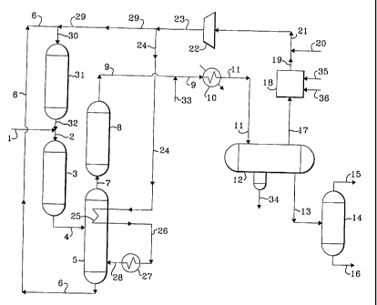
With reference now to the drawing, a feed stream comprising
vacuum gas oil and heavy coker gas oil is introduced into the process via line
1
and admixed with a hereinafter-described effluent from hydrocracking zone 31
transported via line 32. The resulting admixture is transported via line 2
into
hydrotreating zone 3. The resulting effluent from hydrotreating zone 3 is
transported via line 4 and introduced into stripping zone 5. A vaporous stream
containing hydrocarbons and hydrogen passes upward in stripping zone 5 and
contacts heat-exchanger 25 and at least a portion thereof is removed from
stripping zone 5 via line 7 and introduced into post-treat hydrotreating zone
8. A
liquid hydrocarbonaceous stream is removed from stripping zone 5 via line 6
and is introduced into hydrocracking zone 31 via line 6 and line 30. A gaseous
Docket No. 103162 15
CA 02281429 1999-09-03
effluent stream is removed from post-treat hydrotreating zone 8 via line 9 and
is
introduced into heat-exchanger 10. The resulting cooled effluent from heat-
exchanger 10 is transported via line 11 and introduced into vapor-liquid
separator 12. A hydrogen-rich gaseous stream containing acid gas compounds
is removed from vapor-liquid separator 12 via line 17 and is introduced into
acid
gas recovery zone 18. A lean solvent is introduced via line 35 into acid gas
recovery zone 18 and contacts the hydrogen-rich gaseous stream in order to
dissolve an acid gas. A rich solvent containing acid gas is removed from acid
gas recovery zone 18 via line 36 and recovered. A hydrogen-rich gaseous
1 o stream containing a reduced concentration of acid gas is removed from acid
gas
recovery zone 18 via line 19 and is admixed with fresh make-up hydrogen which
is introduced via line 20. The resulting admixture is transported via line 21
and
is introduced into compressor 22. A resulting compressed hydrogen-rich
gaseous stream is transported via line 23 and at least a portion is recycled
via
line 29 and line 30 to hydrocracking zone 31. Another portion of the hydrogen-
rich gaseous stream is transported via line 24 and is introduced into heat-
exchanger 25. The resulting heated hydrogen-rich gaseous stream is removed
from heat-exchanger 25 via line 26 and is introduced into heat-exchanger 27.
The resulting heated hydrogen-rich gaseous stream is removed from heat-
2o exchanger 27 and transported via line 28 and introduced into stripping zone
5.
An aqueous stream is introduced via line 33 and contacts the flowing stream in
line 9 and is subsequently introduced into vapor-liquid separator 12 as
hereinabove described. An aqueous stream containing water-soluble salts is
Docket No. 103162 16
CA 02281429 1999-09-03
removed from vapor-liquid separator 12 via line 34 and recovered. A liquid
stream containing hydrocarbonaceous compounds is removed from vapor-liquid
separator 12 via line 13, reduced in pressure and introduced into separation
zone 14. A gaseous stream containing hydrogen and normally gaseous
hydrocarbons is removed from separation zone 14 via line 15. A liquid stream
containing hydrocarbons is removed from separation zone 14 via line 16 and
recovered.
ILLUSTRATIVE EMBODIMENT
The process of the present invention is further demonstrated by
1 o the following illustrative embodiment. All of the following data were not
obtained
by the actual performance of the present invention but are considered
illustrative of the expected performance of the invention.
A portion of a hydrocracker feedstock having the characteristics
presented in Table 1 is hydrocracked in a conventional single stage
hydrocracker at operating conditions presented in Table 2 to yield the
products
described in Table 3. Another portion of the same hydrocracker feedstock is
hydrocracked in a hydrocracker of the present invention using the same type of
catalyst as the base case at operating conditions presented in Table 2 to
yield
the products described in Table 3. Yields are calculated based on fresh feed
at
start of run conditions.
Docket No. 103162 17
CA 02281429 1999-09-03
TABLE 1 - HYDROCRACKER FEEDSTOCK ANALYSIS
80/20 Blend Straight Run Vacuum Gas Oil-Coker Gas Oil
Gravity, API 21 (927 kg/m3)
Distillation, Volume Percent F C
IBP 664 (351)
716 (379)
30 767 (408)
50 817 436
70 880 (471)
90 965 (518)
FBP 1050 (565)
Sulfur, wt. % 3.01
Nitrogen, PPM 1256
Bromine Number 7.5
Heptane Insolubles, wt. % <0.05
Conradson Carbon, wt. % 0.36
Nickel and Vanadium, PPM 0.4
Docket No. 103162 18
CA 02281429 1999-09-03
TABLE 2- SUMMARY OF OPERATING CONDITIONS
Low Conversion
Per Pass
with Improved
Flowscheme Base Case Yields
Reactor Operating Conditions
High Pressure Separator Pressure 15.96 mPa 11.82 mPa
(2300 psig) (1700 psig)
Liquid Hourly Space Velocity, hr'
Hydrotreating Zone 2.18 1.13
Hydrocracking Zone 0.93 3.0
Overall 0.65 0.82
Combined Feed Ratio **1.5 ***3.0
H2/Fresh Feed 1954 std m3/m 3 1954 std m3Im3
(11,000 SCFB) (11,000 SCFB)
Conversion, Per Pass*, % 60 30
Total (Gross) Conversion, %* 100 100
Number of Gas Quench Points 3 0
Maximum Reactor AT HT/HC 27.8/16.7 C 33.3/27.8 C
(50/30 F) (60/50 F)
* Conversion to 382 C (720 F) End Point Distillate and Lighter
** Recycle Liquid to HT first then to HC
*** Recycle Liquid to HC first then to HT
Docket No. 103162 19
CA 02281429 1999-09-03
TABLE 3 - PRODUCT YIELDS
Base Case Invention
Wt. % VoI. % Wt. % VoI. %
NH3 0.15 0.15
H2S 3.20 3.20
Cl-C4 3.68 2.97
Light Naphtha (C5-C6) 6.32 8.76 5.08 7.04
Heavy Naphtha C7-127 C 10.38 12.87 7.68 9.52
(260 F)
Kerosine 127-288 C (260- 50.16 58.15 48.34 55.92
550 F)
Diesel 288-382 C (550- 28.72 31.98 35.11 39.09
720 F)
Total Middle Distillate 78.88 90.13 83.45 95.01
C5+ Total 95.58 111.76 96.21 111.57
C4+ Total 98.20 116.01 98.32 115.00
Chemical H2 Consumption 2.61 1600 2.53 1550
(SCFB)
From the above tables it is apparent that the present invention is
able to operate at a pressure of 11.8 mPa (1700 psig) or approximately one
fourth less than the base case, utilizes a hydrocracking reactor having about
30% less internal volume as well as about 20% less catalyst inventory.
Because of the lower hydrocracking reactor zone operating severity in the
Docket No. 103162 20
CA 02281429 1999-09-03
present invention, the conversion per pass is reduced from 60% to 30%. These
enumerated changes used in the present invention provide a lower cost
hydrocracking process as well as providing an increased yield of total middle
distillate product. The present invention also has a 8.89 std m3/m3 (50 SCFB)
lower chemical hydrogen consumption and a 50% less hydrogen loss to fuel
gas.
Docket No. 103162 21