Note: Descriptions are shown in the official language in which they were submitted.
CA 02281439 1999-08-25
F t :[
improved starting circuit for low-pressure discharge
lamp
The present invention relates to an operating circuit
for a low-pressure discharge lamp. It specifically
concerns the behaviour of a low-pressure discharge-lamp
immediately after ignition of the discharge in a
starting phase, and also a starting circuit matched to
this behaviour.
A particular known feature of low-pressure discharge
lamps containing Hg is that the luminous flux produced
in the discharge is highly dependent on the temperature
of the lamp. For the user, this means that, after it is
switched on, the lamp provides a noticeably lower
luminous flux for a certain time than when it is being
operated continuously. This starting behaviour is
naturally irritating; however, in the field of lamps
containing Hg, it has not been possible to remedy this
to date with measures concerning the physics of the
lamp itself.
One feasible way is illustrated in German Patent
Specification 195 46 588.1. In this document, the
difficulty described with the starting behaviour of a
low-pressure discharge lamp containing Hg has been
tackled by increasing the lamp-current nominal value of
a control IC that regulates the lamp current in
operation during the starting phase. For further
details, you are referred to the document.
In practice, various difficulties have arisen with such
operating circuits. In particular, increased numbers of
failures have been found.
CA 02281439 2008-10-31
77332-35
2
The invention is thus based on the technical
problem of further developing an operating circuit as
described herein in terms of improved reliability and
improved operating characteristics.
The invention solves this problem in one aspect by
means of a circuit for operating a low-pressure discharge
lamp with a starting circuit for controlling the lamp
current during a starting phase, characterized in that the
starting circuit has a sensor device for a variable which is
dependent on the luminous flux or the temperature of the
lamp, and controls the lamp current depending on the
luminous flux or the temperature of the lamp.
Although the cited document concerns compensation
for excessively low luminous flux when operation starts by
increasing the lamp current, the present invention is not to
be understood as being restricted to this specific case.
Instead, it is based generally on controlling the lamp
current in a starting phase of a low-pressure discharge
lamp.
In another aspect of the invention, there is
provided a circuit for operating a low-pressure discharge
lamp with a starting circuit for controlling the lamp
current during a starting phase, wherein the starting
circuit has a sensor device for a variable which is
dependent on the luminous flux or the temperature of the
lamp, and controls the lamp current depending on the
luminous flux or the temperature of the lamp, the starting
circuit controls the lamp current by varying the duration of
the starting phase, the duration is varied by varying the
counting range of the input of clock pulses from a clock-
signal generator into a counter.
CA 02281439 2008-10-31
77332-35
2a
Embodiments of the invention thus provide for the
lamp current to be controlled in the starting phase
depending on a measured parameter characterizing the
operating state of the lamp. An operating state that
differs from the continuous operating state and in fact
characterizes the starting phase is then intended to cause
the lamp current to be controlled, the result of which is a
lamp luminous flux at least approximating the luminous flux
in the continuous operating state. Specifically, the
operating state can be detected in the starting phase by a
lamp temperature which differs from the continuous operating
temperature of the lamp or by a luminous flux which does not
correspond to the desired continuous luminous flux.
Particularly with the starting
CA 02281439 2008-10-31
77332-35
3
behaviour, descri'DeC: above, of low-;D'_" _ ssur2 C1sc.:arCe
,
lamos co1.LGinin g an excess~vely ! ow _amc
temDe?"ai.ure causes an excessively low luminous =1ux,
which can be comDensated for by rncYeasir_g the lamnp
current in the starting phase.
However, the present invention departs from the
conceot of the document cited above in tnat contro_ of
~__e lamp currer:r is dependent on a measured paYamete_
7=0 which represents the luminous flux or the lamp
temperature. Speclfically, in the prior art described,
a time period which, although it can be set wher the
circuit is designed, is then permanently predefined, is
used for increasing the lamp current in a manner which
is equally permanently predefined. In this case,
although the increased lamp current is raised with a
continuous ramp and is reduced at the end of the
predefined time, the whole pattern of times for
increasing, maintaining and reducing the increased lamp
current and for the extent of the increase in terms o_
current level is permanent and invariable for
individual cases, irrespective of the actual operating
state of the lamp.
According to the invention, it has been found that this
inflexible" control of the lamp current does not
merely result in relatively poor matching of the
luminous flux in the starting phase. Above all, the
inflexibly predefined lamp current increase w'r_enever
the lamp is started can cause the lamp or the onerGting
circuit to be damaged. For example, when a low-pressure
discharge lamp containing Hg is restarted after a short
interruption in operation, the lamp is still wGrm fro:~:
operation. Increasing the lamp current can tnen
increase the operating temperature above the r_om:ina_j
temperature for cont_nuous operation, so that the
1 uminous flux oT the lam,o is reduced again on accounit
of the excessive Hg vaDOL'r pressure. The result -s
CA 02281439 1999-08-25
- 4 -
that, for this case, the starting circuit achieves the
exact opposite of the desired result. In addition, the
increased temperature accelerates the deterioration and
thus the probability of failure of the lamp and the
electronic components in its immediate surroundings. A
similar line of reasoning also applies to the rising
temperature, caused by the increased lamp current, of
the= operating circuit even if it is not arranged
immediately next to the lamp.
If, owing to particular circumstances, the lamp or the
operating circuit has already overheated before
restart, the lamp current increase which nevertheless
takes place can result in destruction. This risk is
also present if the lamp is repeatedly switched on and
off for brief periods even if the surrounding
conditions are otherwise normal.
The invention instead makes control of the lamp current
and, in the example given, the lamp current increase
dependent on the measured parameter characterizing the
operating state of the lamp. Accordingly, the lamp
current control can then be controlled on the basis of
duration, relative increase or reduction or on the
basis of sign as well as activation or deactivation. It
is helpful to use one or more measured parameters
which, directly or indirectly, characterize either the
luminous flux of the lamp or the lamp temperature.
In a preferred refinement, a temperature sensor is
provided which does not measure the lamp temperature
directly -but measures a temperature which depends on
the lamp temperature. This concerns, by way of example,
measurement points in the lamp base and/or in the
operating circuit or at other points which are
thermally coupled to the lamp. In a specific case, such
a temperature sensor is designed to be integrated with
a control IC for the operating circuit. Control ICs are
preferred in this invention because the possibility
CA 02281439 1999-08-25
- 5 -
exists for combination with a regulating circuit in the
operating circuit. The starting circuit and the sensor
device, i.e. the temperature sensor, can then also be
integrated in the IC.
In addition, a photodetector may also be used which
measures the luminous flux of the lamp. In this
instance, detection of the luminous flux by means of
the photodetector, at least in discharge lamps
containing Hg, should=preferably take place in addition
to the temperature being detected. Otherwise, an
overheating operating state cannot reliably be
distinguished from a cold start because the luminous
flux decreases with an increased Hg vapour pressure in
exactly the same way as with execessively low Hg vapour
pressure.
Instead of the lamp luminous flux, the running voltage
of the lamp can also be measured in the operating
circuit. In discharge lamps containing Hg, the same
applies here as for the dependency of the luminous flux
on the lamp temperature.
In a simple and effective variant of the invention, the
lamp current can be controlled by varying the time
period for a lamp current increase or reduction. In the
more complex case, this takes place together with
variation of the extent of the current strength, but
happens exclusively in the simplest case. Deactivation
can be achieved by setting the time period to zero or
very much shortening it. In this case, preferred
embodiments for the necessary timer circuit, on the one
hand, are a combination of a clock-signal generator and
a counter with possible variation of the clock
frequency or of the final counter reading of the
counter, the said reading determining the time. The
range of the clock input to the counter can also be
varied, so that the counter accordingly counts at a
higher point and thus reaches a value defining a
CA 02281439 2008-10-31
77332-35
6
time period earlier. On the other hand, a combination
comprising an RC element and a comparator is feasible,
the time constant of the RC element and the thrLshold
of the comparator again being variable.
A further refinement of the invention relates to the
temperature detection already mentioned above.
Particularly if there is insufficient thermal coupling
between the lamp and the measurement point, which, for
technical reasons, may possibly desirably be ou~side
the lamp, the measurement point can be arranged on a
component which produces heat independently of the lamp
during lamp operation. This component may be, for
example, part of the control IC mentioned or the er_tire
IC. However, power transistors for an oscillator ana
similar heat-producing components are also feasi.ble,
for example.
In the following text, a specific exemplary embodiment
is described with reference to the figures, and' the
individual features of .the exemplary embodiment may
also be essential to the invention in different
combinations or individually.
For the sake of simplicity, this exemplary embodiment
is based on the ci-rcuit described in the cited document
DE 195 46 588.1. Hence, reference is made to th_s
document with regard to the basic manner of operation,
control of the lamp current in particular, and t^e
design of the operating circuit and the control ~C.
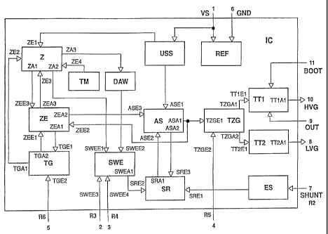
In this case, the figure corresponds to Figure 2 of the
cited application and shows a functi-onal block diagram
of a control IC which has been expanded, according to
the present invention, in comparison with the cited
Figure 2 of the prior application.
CA 02281439 1999-08-25
- 7 -
A new block TM for a temperature sensor has been
inserted into the block diagram and detects the
temperature of the silicon IC shown. The block TM is
connected by means of a new input ZE4 to the counter Z,
which is already known from the cited application. Both
blocks are situated in the top left-hand corner of the
figure.
For actually designing such a temperature sensor,
various options are known to a person skilled in the
art. In particular, highly temperature-dependent
electrical variables (e.g. leakage currents or diode
forward voltages) can be compared with temperature-
compensated reference variables. Specific examples
of appropriate practical transistor circuits
are illustrated, for example, in " Halbleiter-
schaltungstechnik [Semiconductor Circuitry]" by U.
Tietze, Ch. Schenk, 9th edition, Springer, section
26.1.5 (transistor as temperature sensor) page 897-
901.
In the exemplary embodiment shown, the temperature
sensor TM compares the measured value with a reference
value in order to determine a digital signal whose two
possible values (1' or 0) represent an IC temperature
above or below the reference variable. This digital
signal is input into the input ZE4 of the counter Z.
The counter Z.reacts to the value of the signal from
the temperature sensor TM by the clock pulses,
predefined by the clock-signal generator TG already
known from the prior application, for counting up the
counter Z occurs at a different position (in terms of a
multi-digit binary number) or with a different range.
The clock pulses are thus not transferred to the least
significant element but to an element which is more
significant by a predetermined factor.
CA 02281439 1999-08-25
= .
- 8 -
The counter Z can comprise, for example, a chain of a
number of flipflops (e.g. 22) whose output frequency
halves the input frequency in each case. Inputting the
clock pulses at the thirteenth flipflop, for example,
instead of the first flipflop, effectively shortens the
time by a factor of 212 until a specific counter reading
is reached.
However, this shortening of the time affects only the
times linked to the starting phase and not the length
of time for the preheating and ignition phase. To refer
to Figure 4a of the cited application, the length of
time TV for the preheating phase and TZ for the
ignition phase thus remains unchanged until ignition is
detected. Preheating is fundamentally necessary and
largely independent of the general operating
temperature of the lamp.
In the circuit shown in the appended figure, this means
that the counting properties of the counter Z are
varied by the signal from the temperature sensor TM via
the input ZE4 only if the ignition detector ZE " has
informed" the counter, via the input ZE3, that the
preheating and ignition process has now ended.
The essential advantage of the solution according to
the invention is that the rest of the circuit remains
completely unchanged from a technical point of view,
and so the other conventional nominal value stages
(illustrated in Figure 4a of the cited application) are
run through so quickly that the starting phase is
practically dispensed with.
Reference is additionally made to the description of
the cited prior application.