Note: Descriptions are shown in the official language in which they were submitted.
CA 02281759 1999-08-20
WO 99/34086 PCT/GB98/03891
-1-
IMPROVED AUGER CLEANERS
The present invention relates to tools for
cleaning an auger, in particular but not exclusively a
continuous flight auger, as it is being withdrawn or
after it has been withdrawn from the ground.
Augers are commonly used in civil engineering
applications such as piling, a particular example of
this being Continuous Flight Auger (CFA) piling. A
continuous flight auger comprises a generally
cylindrical elongate body provided with a generally,
helical blade. Each 360 turn of the auger defines a
flight of the blade, i.e. a flight is the space between
adjacent, longitudinally-spaced sections of the blade.
In use, the auger is rotated into the ground to a
predetermined depth at which the downward advance of
the auger is halted. Thelauger may then be withdrawn
without further rotation, thereby shearing a plug" of
soil directly from the ground so as to form a bore
hole, or the auger may be rotated before withdrawal so
as to shear the soil on the flights from the soil which
will eventually form the wall of the resultant bore
hole. During withdrawal, concrete or grout may be
pumped through the auger or down a.feed pipe under
positive pressure so as to form a cast-.in-situ pile.
Upon withdrawal, the flights of the auger are
generally loaded with soil, and there is a danger.that
some of this soil will become locked between adjacent
flights instead of falling out cleanly as the auger
emerges above ground level. As the auger continues to
be withdrawn, the flights with the locked-in soil will
be raised to levels some distance (typically up to 20m)
above the ground, and there is a significant danger
that the locked-in soil may loosen and fall onto
operating personnel on the ground, possibly causing
serious injury. This is becoming more of a problem
SUBSTT'TUTE SHEET (RULE 26
CA 02281759 1999-08-20
WO 99/34086 PCT/GB98/03891
-2-
with modern CFA piling techniques, since these often
require a tight entry into the ground which results in
soil being packed onto the flights in a particularly
dense and compact manner.
Traditionally, augers have been cleaned by hand,
for example by using a scraping implement and sometimes
water jets. This, however, is labour intensive and can-
be dangerous.
It is known from GB 2 235 480 A(amaizgst others)
to scrape soil off the flights of a rotating auger by
deploying a toothed wheel.next to the auger in the
manner of a worm drive. As the auger rotates, so does
the wheel, the teeth of the wheel engaging between the
flights and thereby scraping off locked-in soil. This
technique is.not particularly effective, since only
soil locked in a single flight is attacked at any one
time. Furthermore, if the auger is being withdrawn
rather than merely being rotated out of =theground,
then the toothed wheel will tend to miss sections of
the auger flights.
According to the present invention, there is
provided a tool for removing debris from the flights of
an auger or other screw-conveyor, the tool comprising a
central shaft about which is helically arranged a
plurality of radially projecting elements.
In use, the tool is mounted adjacent to an auger,
with the central shaft being substantially parallel to
the auger stem. Advantageously, the tool is mounted in
such a way that it can be moved near to and away from
the auger in such a way that the projecting elements
may be gradually introduced to the auger flights.
Cleaning the auger in this manner is assisted by way of
soil being packed more loosely between the flights at
the top of the auger than between those at the bottom.
The radially projecting elements are arranged in a
helix which has substantially the same pitch as that of
SUBSTITUTE SHEET (RULE 26
CA 02281759 1999-08-20
WO 99/34086 PCT/GB98/03891
-3-
the auger blade. As the auger is withdrawn from the
ground, the tool is brought up to the auger and rotated
so that the projecting elements engage with the auger
flights. The rate and direction of rotation is
dependent on the rate of withdrawal of the auger.and
whether or not the auger is also being rotated. In
general, where the projecting elements are disposed in
a helix having the opposite sense to that of the auger
blade, then the tool must be rotated in the opposite
direction to the auger so as to counter flight
movement. Alternatively, the projecting elements may
be disposed in a helix having the same sense as that of
the auger blade, in which case the tool is rotated in
the same direction.as the auger. The former
arrangement may be advantageous in that the angle of
attack of the projecting elements on the flights of the
auger is increased, and any locked-in soil will tend to
be pushed downwards.
It is also possible to clean the auger without
continuous rotation upon extraction. The auger may,
for example, be repeatedly turned forwards by half a
turn and then backwards by half a turn, with the tool
rotating accordingly.
A particular advantage of the present invention is
that it can be used in applications where an auger is
rotated relatively slowly during withdrawal. This is
because the projecting elements simultaneously
penetrate adjacent flights of the auger. Furthermore,
since rotation of the tool allows continuous parallel
movement between the tool and the auger, the tool does
not need to be separated from and repositioned on the
auger as it is withdrawn. This helps to ensure that no
sections along the length of the auger are missed.
Advantageously, two, three or more tools may be
disposed substantially equiangularly about the auger so
as to attack soil on the auger flights from a number of
SUBSTITUTE SHEET (RULE 26
CA 02281759 1999-08-20
WO 99/34086 PCT/GB98/03891
-4-
directions simultaneously. Such an arrangement,
particularly with three tools, also means that any
lateral forces which may tend to push a single tool and
the auger away from each other may be balanced out.
The tool may be rotated by way of a mechanical
linkage which couples the tool to the auger drive
means. Such a linkage, which may take the form of a
bushing or other driving arrangement, automatically
synchronises the rotations of the tool and the auger so
as to prevent relative fouling..
Alternatively, the tool may be rotated by way of
an independent electric or hydraulic motor. In order
to ensure synchronisation with the rotation of the
auger, sensors are provided which detect the proximity
of the auger flights to the tool. When a sensor
detects that the tool and.the auger are not in
synchronisation, i.e. the..projecting..elements are not
disposed substantially in the middle of each flight,
appropriate rotation of the tool is commanded so as to
bring the projecting elements back to the mid-point of
each flight. On-board instrumentation and computer
means may be provided so as to allow complete control
of the tool. For example, given the angle of rotation
of the auger, the depth change and the pitch of the
auger blade, it is possible to calculate and apply the
correct rate of rotation to the tool so as to ensure
synchronisation with the auger.
The radially projecting elements may take the form
of blades, cutting tools, digging tools, brushes and
any combination thereof. It is generally preferred to
include at least one blade or cutting tool, since soil
removal is facilitated by cutting a groove into the
locked-in soil so as to allow the same to swell and
hence to fall away from the auger. The radial
extension of at least some of the projecting elements
should be at least as great as the radius of the
SUBSTITUTE SHEET (RULE 26
CA 02281759 1999-08-20
WO 99/34086 PCT/GB98/03891
-5-
largest auger with which the tool is to be used. This
is to ensure that the flights are cleaned thoroughly.
In some embodiments, the envelope defining the radial
extension of the projecting elements may be selected to
start from the diameter of the central.shaft at the
lower end of the tool and gradually to increase along
the length of the tool until full penetration of the
auger flights is achieved. A further feature is that
different projecting elements may be arranged along the
length of the tool so as to facilitate the removal of
different conditions of soil, for example loosely- or
densely-packed. For example, brushes can be arranged
at the top of the tool so as to complete the auger
cleaning operation. The projecting elements need not
be permanently attached to the central shaft of the
tool, but may be readily interchanged so as to allow
the tool to be tailored to specific applications.
In embodiments where the tool is mounted so that
it may be moved near to and away from the auger,
generally by way of a pivot, it is possible to swing
the tool out of the way of any drive head which may be
mounted at the top of the auger, thereby allowing the
auger to be rotated into the ground to a greater depth
than would otherwise be possible. One way in which
this may be achieved is to drive the tool from its
lower end.
For a better understanding of the present
invention, and to show how it may be carried into
effect, reference will now be-made, by way of example,
to the following drawings, in which:
FIGURE 1 shows an auger cleaning tool engaged with
an auger;
FIGURE 2 shows a pivotally-mounted auger cleaning
tool engaged with an auger; and
FIGURE 3 shows the auger cleaning tool of Figure 2
moved to a position away from the auger.
SUBSTITUTE SHEET (RULE 26
CA 02281759 1999-08-20
WO 99/34086 PCT/GB98/03891
-6-
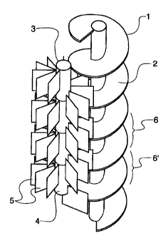
Figure 1 shows an auger 1 having a blade 2. A
tool 3, comprising a central shaft 4 on which are
removably mounted a number of flat blades 5 in a
helical formation, engages,with the blade 2 of the
auger 1. The pitch of the blades 5 is substantially
the same as the pitch of the auger blade 2, and the
sense of the helical arrangement of the blades 5 is
opposite to that of the blade 2. In the embodiment
shown, the tool 3 has a length of around 1 to 2m, and
the auger 1 has a length of up to 20m. In use, as the
auger 1 is withdrawn from the ground, the tool 3 is
rotated so as to counter the movement of the blade 2 of
the auger 1. Rotation of the tool 3 is synchronised
with rotation of the auger 1 so that the blades 5
penetrate adjacent flights 6, 6' without fouling the
blade 2 itself. In this way, any soil (not shown)
locked into the flights 6., 6' of the.auger 1 is
effectively removed.
An alternative arrangement is shown in Figures 2
and 3, where an auger cleaning tool 7 is pivotably
mounted next to an auger 8. The auger 8 is rotated by
way of a drive head 9 mounted at the top of the auger
8. The drive head also serves to rotate the tool 7 in
the appropriate direction by way of a shaft 10 and
mechanical linkages 11 and 12. As shown best in Figure
3, the tool 7 may be swung away from the auger 8 so
that it no longer engages with the flights 13, 13' of
the auger, thereby allowing the drive head 9 to pass by
most of the body of the tool 7 and thereby enabling the
auger to penetrate the ground to a deeper level than
would otherwise be the case.
SUBSTITUTE SHEET (RULE 26