Language selection

Search

Patent 2281851 Summary

Third-party information liability

Some of the information on this Web page has been provided by external sources. The Government of Canada is not responsible for the accuracy, reliability or currency of the information supplied by external sources. Users wishing to rely upon this information should consult directly with the source of the information. Content provided by external sources is not subject to official languages, privacy and accessibility requirements.

Claims and Abstract availability

Any discrepancies in the text and image of the Claims and Abstract are due to differing posting times. Text of the Claims and Abstract are posted:

  • At the time the application is open to public inspection;
  • At the time of issue of the patent (grant).
(12) Patent: (11) CA 2281851
(54) English Title: PORTABLE HAZARD-WARNING DEVICE
(54) French Title: DISPOSITIF DE SIGNALISATION DE DANGER PORTABLE
Status: Deemed expired
Bibliographic Data
(51) International Patent Classification (IPC):
  • G08B 5/36 (2006.01)
  • E01F 9/615 (2016.01)
  • B60Q 7/00 (2006.01)
(72) Inventors :
  • WANG, SHIUNN TERNY (Taiwan, Province of China)
(73) Owners :
  • JASON EL TECHNOLOGY CO., LTD. (Taiwan, Province of China)
(71) Applicants :
  • WANG, SHIUNN TERNY (Taiwan, Province of China)
(74) Agent: PERLEY-ROBERTSON, HILL & MCDOUGALL LLP
(74) Associate agent:
(45) Issued: 2001-12-04
(22) Filed Date: 1999-09-10
(41) Open to Public Inspection: 2001-03-10
Examination requested: 1999-09-10
Availability of licence: N/A
(25) Language of filing: English

Patent Cooperation Treaty (PCT): No

(30) Application Priority Data: None

Abstracts

English Abstract


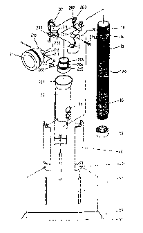
A hazard-warning device includes a shank portion
with lights and batteries received therein and a flange
extending radially outward therefrom. A flashlight head is
pivotally connected to the shank portion and two buttons
are respectively attached to the shank portion to control
the flashlight head and the lights. A sleeve is slidably
mounted to the shank portion and limited between the
flashlight head and the flange. Three legs are
respectively and pivotally connected to the sleeve and
three expanding rods are respectively and pivotally
connected between the legs and the shank portion. A first
cap is threadedly connected to the lower end of the shank
portion and a second cap is attached to the three legs and
sized to receive the respective three lower ends of the
three legs.


Claims

Note: Claims are shown in the official language in which they were submitted.


I CLAIM:

1. A hazard-warning device comprising:
a shank portion having lights received therein
and a serrated outer periphery extending radially outwardly
therefrom, a first button and a second button respectively
attached to said shank portion;
a neck portion rotatably connected to the first
end of said shank portion and a flashlight head pivotally
connected to said neck portion;
a sleeve slidably mounted to said shank portion
and being limited between said flashlight head and said
serrated outer periphery;
three legs each having the first end thereof
pivotally connected to said sleeve and three expanding rods
respectively and pivotally connected between said legs and
the second end of said shank portion, and
a first cap threadedly connected to the second
end of said shank portion and a second cap attached to said
three legs and being sized to receive the respective three
second ends of said three legs.
2. The device as claimed in claim 1, further
comprising a transverse plate detachably connected between
two of said three legs.
3. The device as claimed in claim 2, wherein said
transverse plate has two stubs extending from two ends
thereof and said two of said three legs each has a hole
defined through the second end thereof so as to receive the
stubs therein.
4. The device as claimed in claim 1, wherein said
sleeve has two holes defined therethrough which communicate
with said first button and said second button when said
sleeve is positioned close to the first end of said shank
portion.
-6-


5. The device as claimed in claim 1, wherein said
sleeve has an enlarged end defined thereto which is
disengagably engaged with said flashlight head.
6. The device as claimed in claim 1, wherein said
sleeve has a serrated outer periphery.
7. The device as claimed in claim 1, wherein said
neck portion has two tubes extending inwardly therefrom and
said flashlight head has a tongue extending therefrom which
has a hole to receive said two tubes.
8. The device as claimed in claim 1, further
comprising a base connected to said first end of said shank
portion and said neck portion rotatably mounted to said
base portion.
9. The device as claimed in claim 8, wherein said
neck portion has a skirt portion in which said base is
received, two flanges and a first rib respectively
extending radially inward therefrom, said base having two
annular grooves respectively defined therein so as to
receive said two flanges therein, a second rib extending
radially outward from said base so that the neck portion is
limited when said first rib contacts said second rib.

-7-

Description

Note: Descriptions are shown in the official language in which they were submitted.


CA 02281851 1999-09-10
PORTABLE HAZARD-WARNING DEVICE
FIELD OF THE INVENTION
The present invention relates to a hazard-warning
device, and more particularly, to a multi-purpose hazard
s warning device which includes a pivotable head used as a
flashlight, a shank portion having lights disposed therein
and three light-reflective legs pivotably connected to a
sleeve slidably mounted to the shank portion.
BACKGROUND OF THE INVENTION
A warning device known to the applicant is
disclosed in the U.S. Patent No. 4,922,223 to Prevot,
entitled as "Emergency Identifier For Vehicles" issued on
May 1, 1990. The warning device disclosed in the
referenced U.S. Patent No. 4,922,223 has a large volume and
complicated structure, so that the device cannot be used
conveniently. That is to say, the device occupies the
space of the trunk of the vehicle and has only one feature
which can be used when an emergent case happens on the
road, the user will not use the device in a general
situation such as to find something in the dark. Although
the device has warning words shown in the board thereof ,
the board is deemed to be so large that it tends to be
blown down by the wind especially when standing the device
on the shoulder portion of the highway. This could be
dangerous to the cars passing by.
The present invention intends to provide a
portable hazard-warning device which has a compact size and
a plurality of functions so that the device of the present
invention can be used in many situations. Three light-
reflective legs are pivotally connected to the device so
that they can be expanded to form a triangle. A flashlight
head is pivotally connected to the device so that the
device can be used as a flashlight in the dark.
The warning device further has lights disposed in
the transparent shank portion thereof so that it can be
- 1 -


CA 02281851 1999-09-10
seen from a far distance when standing on the road and
provides sufficient time to react properly for the vehicles
followed behind.
SUMMARY OF THE INVENTION
In accordance with one aspect of the present
invention, there is provided a hazard-warning device
comprising a shank portion having lights received therein
and a flange extending radially outward therefrom. A neck
portion is rotatably connected to the first end of the
shank portion and a flashlight head is pivotally connected
to the neck portion. Two buttons are respectively attached
to the shank portion to control the flashlight head and the
lights.
A sleeve is slidably mounted to the shank portion
and limited between the flashlight head and the flange.
Three legs each have the first end thereof pivotally
connected to the sleeve and three expanding rods are
respectively and pivotally connected between the legs and
the second end of the shank portion.
2 0 A first cap is threadedly connected to the second
end of the shank portion and a second cap is attached to
the three legs and sized to receive the respective three
second ends of the three legs.
The main object of the present invention is to
provide a portable hazard-warning device which can be used
as a triangle frame, a flashlight and a light emitting
warning device.
Further objects, advantages, and features of the
present invention will become apparent from the following
detailed description with appropriate reference to the
accompanying drawings.
BRIEF DESGRIPTTON OF THE DRAWINGS
Figure 1 is an exploded view of the warning
device in accordance with the present invention;
- 2 -


CA 02281851 1999-09-10
Figure 2 is an illustrative view to illustrate
the flashlight head pivotally connected to the neck
portion;
Figure 3 is an illustrative view to illustrate
the engagement between the neck portion and the flashlight
head;
Figure 4 is a side elevational view, partly in
section, of the warning device in accordance with the
present invention, wherein the three legs are retracted
toward the shank portion, and
Figure 5 is a side elevational view, partly in
section, of the warning device in accordance with the
present invention, wherein the three legs are expanded
outwardly to form a triangle.
DETAILED DESCRIPTION OF THE PREFERRED EMBODIMENT
Referring to Figures 1 to 3, the hazard-warning
device in accordance with the present invention comprises
a shank portion 10 having lights and batteries received
therein and the shank portion 10 is made of transparent
material so that light can be seen via the shank portion 10
when the lights are turned on. The shank portion 10 has a
serrated outer periphery 130 extending radially outward
therefrom. A first button 13 and a second button 14 are
respectively attached to the shank portion 10.
A neck portion 20 composed of two parts is
connected to a base 200 which is rotatably connected to the
first end of the shank portion 10. The neck portion 20 has
a skirt portion 23 in which the base 200 is received, two
flanges 231, 232 and a first rib 233 respectively extending
radially inward therefrom. The base 200 has two annular
grooves 204, 205 respectively defined therein so as to
receive the two flanges 231, 232 therein and a second rib
206 extends radially outward from the base 200 so that the
neck portion 20 is limited when the first rib 233 contacts
the second rib 206. A flashlight head 21 has a tongue 210
extending therefrom which has a hole 211 defined
- 3 -


CA 02281851 1999-09-10
therethrough. Each of the two parts of the neck portion 20
has two tubes 201 extending inwardly therefrom to each of
which a ring member 202 is mounted. The two tubes 201 are
received in the hole 211 with a bolt 2110 extending through
the two tubes 201 and the hole 211 so that the flashlight
head 21 is pivotable corresponding to the neck portion 20.
Each of the ring members 202 has a serrated inner surface
203 and the tongue 210 further has two apertures 212 each
of which has a spring 22 and a pin 220 received therein so
that when the flashlight head 21 is pivotably connected to
the neck portion 20, the pins 220 will contact the serrated
inner surfaces 203 of the two ring members 202 to provide
a closed circuit if the first button 13 is pushed.
A sleeve 30 is slidably mounted to the shank
portion 10 and limited between the flashlight head 21 and
the serrated outer periphery 130. The sleeve 30 has two
holes 31 defined therethrough which communicate with the
first button 13 and the second button 14 when the sleeve 30
is positioned close to the first end of the shank portion
10 so that the user may operate the two buttons 13, 14
through the two holes 31. The sleeve 30 further has an
enlarged end 301 defined thereto which is disengagably
engaged with the flashlight head 21 to position the
flashlight head 21 in an upright position.
Three legs 40 each have the first end thereof
pivotally connected to the sleeve 30 and three expanding
rods 41 are respectively and pivotally connected between
the legs 40 and the second end of the shank portion 10, so
that when the sleeve 30 is moved toward the flashlight head
21, the three legs 40 are moved close to the shank portion
10 as shown in Figure 4. A first cap 50 is threadedly
connected to the second end of the shank portion 10 so as
to replace batteries when needed. A second cap 51 is
attached to the three legs 40 and sized to receive the
respective three second ends of the three legs 40 as shown
in Figure 4. A transverse plate 60 is detachably connected
between two of the three legs 40 to form a triangle as
- 4 -


CA 02281851 1999-09-10
shown in Figure 5, wherein the transverse plate 60 has two
stubs 61 extending from two ends thereof and the two of the
three legs 40 each has a hole 401 defined through the
second end thereof so as to receive the stubs 61 therein.
Accordingly, the warning device in accordance
with the present invention has a plurality of functions,
which can be performed as a flashlight, a triangle frame
and a light emitting warning device. It is to be noted
that the device has a compact size as shown in Figure 4 so
that it occupies a limited space and can be used as a
directing rod when the lights are turned on in the dark.
Each of the three legs 40 and the transverse plate 60 are
covered with light reflective material so that they can be
seen from a long distance.
The invention is not limited to the above
embodiment but various modification thereof may be made.
It will be understood by those skilled in the art that
various changes in form and detail may be made without
departing from the scope and spirit of the present
invention.
- 5 -

Representative Drawing
A single figure which represents the drawing illustrating the invention.
Administrative Status

For a clearer understanding of the status of the application/patent presented on this page, the site Disclaimer , as well as the definitions for Patent , Administrative Status , Maintenance Fee  and Payment History  should be consulted.

Administrative Status

Title Date
Forecasted Issue Date 2001-12-04
(22) Filed 1999-09-10
Examination Requested 1999-09-10
(41) Open to Public Inspection 2001-03-10
(45) Issued 2001-12-04
Deemed Expired 2007-09-10

Abandonment History

There is no abandonment history.

Payment History

Fee Type Anniversary Year Due Date Amount Paid Paid Date
Request for Examination $200.00 1999-09-10
Application Fee $150.00 1999-09-10
Final Fee $150.00 2001-08-23
Maintenance Fee - Application - New Act 2 2001-09-10 $50.00 2001-08-27
Registration of a document - section 124 $100.00 2002-04-03
Maintenance Fee - Patent - New Act 3 2002-09-10 $50.00 2002-09-09
Maintenance Fee - Patent - New Act 4 2003-09-10 $50.00 2003-09-02
Maintenance Fee - Patent - New Act 5 2004-09-10 $100.00 2004-09-01
Maintenance Fee - Patent - New Act 6 2005-09-12 $100.00 2005-09-08
Owners on Record

Note: Records showing the ownership history in alphabetical order.

Current Owners on Record
JASON EL TECHNOLOGY CO., LTD.
Past Owners on Record
WANG, SHIUNN TERNY
Past Owners that do not appear in the "Owners on Record" listing will appear in other documentation within the application.
Documents

To view selected files, please enter reCAPTCHA code :


To view images, click a link in the Document Description column. To download the documents, select one or more checkboxes in the first column and then click the "Download Selected in PDF format (Zip Archive)" or the "Download Selected as Single PDF" button.

List of published and non-published patent-specific documents on the CPD .

If you have any difficulty accessing content, you can call the Client Service Centre at 1-866-997-1936 or send them an e-mail at CIPO Client Service Centre.


Document
Description 
Date
(yyyy-mm-dd) 
Number of pages   Size of Image (KB) 
Cover Page 2001-10-30 2 46
Cover Page 2001-02-14 1 40
Representative Drawing 2001-02-14 1 14
Representative Drawing 2001-10-30 1 13
Abstract 1999-09-10 1 24
Description 1999-09-10 5 229
Claims 1999-09-10 2 72
Drawings 1999-09-10 5 88
Correspondence 2001-08-23 1 25
Fees 2003-09-02 1 25
Fees 2004-09-01 1 29
Assignment 1999-09-10 4 88
Assignment 2002-04-03 4 111
Fees 2002-09-09 1 26
Fees 2005-09-08 1 26