Sélection de la langue

Search

Sommaire du brevet 2281851 

Énoncé de désistement de responsabilité concernant l'information provenant de tiers

Une partie des informations de ce site Web a été fournie par des sources externes. Le gouvernement du Canada n'assume aucune responsabilité concernant la précision, l'actualité ou la fiabilité des informations fournies par les sources externes. Les utilisateurs qui désirent employer cette information devraient consulter directement la source des informations. Le contenu fourni par les sources externes n'est pas assujetti aux exigences sur les langues officielles, la protection des renseignements personnels et l'accessibilité.

Disponibilité de l'Abrégé et des Revendications

L'apparition de différences dans le texte et l'image des Revendications et de l'Abrégé dépend du moment auquel le document est publié. Les textes des Revendications et de l'Abrégé sont affichés :

  • lorsque la demande peut être examinée par le public;
  • lorsque le brevet est émis (délivrance).
(12) Brevet: (11) CA 2281851
(54) Titre français: DISPOSITIF DE SIGNALISATION DE DANGER PORTABLE
(54) Titre anglais: PORTABLE HAZARD-WARNING DEVICE
Statut: Réputé périmé
Données bibliographiques
(51) Classification internationale des brevets (CIB):
  • G08B 5/36 (2006.01)
  • E01F 9/615 (2016.01)
  • B60Q 7/00 (2006.01)
(72) Inventeurs :
  • WANG, SHIUNN TERNY (Taïwan, Province de Chine)
(73) Titulaires :
  • JASON EL TECHNOLOGY CO., LTD. (Taïwan, Province de Chine)
(71) Demandeurs :
  • WANG, SHIUNN TERNY (Taïwan, Province de Chine)
(74) Agent: PERLEY-ROBERTSON, HILL & MCDOUGALL LLP
(74) Co-agent:
(45) Délivré: 2001-12-04
(22) Date de dépôt: 1999-09-10
(41) Mise à la disponibilité du public: 2001-03-10
Requête d'examen: 1999-09-10
Licence disponible: S.O.
(25) Langue des documents déposés: Anglais

Traité de coopération en matière de brevets (PCT): Non

(30) Données de priorité de la demande: S.O.

Abrégés

Abrégé anglais


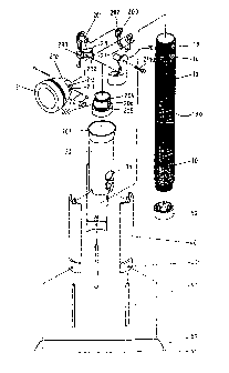
A hazard-warning device includes a shank portion
with lights and batteries received therein and a flange
extending radially outward therefrom. A flashlight head is
pivotally connected to the shank portion and two buttons
are respectively attached to the shank portion to control
the flashlight head and the lights. A sleeve is slidably
mounted to the shank portion and limited between the
flashlight head and the flange. Three legs are
respectively and pivotally connected to the sleeve and
three expanding rods are respectively and pivotally
connected between the legs and the shank portion. A first
cap is threadedly connected to the lower end of the shank
portion and a second cap is attached to the three legs and
sized to receive the respective three lower ends of the
three legs.

Revendications

Note : Les revendications sont présentées dans la langue officielle dans laquelle elles ont été soumises.


I CLAIM:

1. A hazard-warning device comprising:
a shank portion having lights received therein
and a serrated outer periphery extending radially outwardly
therefrom, a first button and a second button respectively
attached to said shank portion;
a neck portion rotatably connected to the first
end of said shank portion and a flashlight head pivotally
connected to said neck portion;
a sleeve slidably mounted to said shank portion
and being limited between said flashlight head and said
serrated outer periphery;
three legs each having the first end thereof
pivotally connected to said sleeve and three expanding rods
respectively and pivotally connected between said legs and
the second end of said shank portion, and
a first cap threadedly connected to the second
end of said shank portion and a second cap attached to said
three legs and being sized to receive the respective three
second ends of said three legs.
2. The device as claimed in claim 1, further
comprising a transverse plate detachably connected between
two of said three legs.
3. The device as claimed in claim 2, wherein said
transverse plate has two stubs extending from two ends
thereof and said two of said three legs each has a hole
defined through the second end thereof so as to receive the
stubs therein.
4. The device as claimed in claim 1, wherein said
sleeve has two holes defined therethrough which communicate
with said first button and said second button when said
sleeve is positioned close to the first end of said shank
portion.
-6-


5. The device as claimed in claim 1, wherein said
sleeve has an enlarged end defined thereto which is
disengagably engaged with said flashlight head.
6. The device as claimed in claim 1, wherein said
sleeve has a serrated outer periphery.
7. The device as claimed in claim 1, wherein said
neck portion has two tubes extending inwardly therefrom and
said flashlight head has a tongue extending therefrom which
has a hole to receive said two tubes.
8. The device as claimed in claim 1, further
comprising a base connected to said first end of said shank
portion and said neck portion rotatably mounted to said
base portion.
9. The device as claimed in claim 8, wherein said
neck portion has a skirt portion in which said base is
received, two flanges and a first rib respectively
extending radially inward therefrom, said base having two
annular grooves respectively defined therein so as to
receive said two flanges therein, a second rib extending
radially outward from said base so that the neck portion is
limited when said first rib contacts said second rib.

-7-

Description

Note : Les descriptions sont présentées dans la langue officielle dans laquelle elles ont été soumises.


CA 02281851 1999-09-10
PORTABLE HAZARD-WARNING DEVICE
FIELD OF THE INVENTION
The present invention relates to a hazard-warning
device, and more particularly, to a multi-purpose hazard
s warning device which includes a pivotable head used as a
flashlight, a shank portion having lights disposed therein
and three light-reflective legs pivotably connected to a
sleeve slidably mounted to the shank portion.
BACKGROUND OF THE INVENTION
A warning device known to the applicant is
disclosed in the U.S. Patent No. 4,922,223 to Prevot,
entitled as "Emergency Identifier For Vehicles" issued on
May 1, 1990. The warning device disclosed in the
referenced U.S. Patent No. 4,922,223 has a large volume and
complicated structure, so that the device cannot be used
conveniently. That is to say, the device occupies the
space of the trunk of the vehicle and has only one feature
which can be used when an emergent case happens on the
road, the user will not use the device in a general
situation such as to find something in the dark. Although
the device has warning words shown in the board thereof ,
the board is deemed to be so large that it tends to be
blown down by the wind especially when standing the device
on the shoulder portion of the highway. This could be
dangerous to the cars passing by.
The present invention intends to provide a
portable hazard-warning device which has a compact size and
a plurality of functions so that the device of the present
invention can be used in many situations. Three light-
reflective legs are pivotally connected to the device so
that they can be expanded to form a triangle. A flashlight
head is pivotally connected to the device so that the
device can be used as a flashlight in the dark.
The warning device further has lights disposed in
the transparent shank portion thereof so that it can be
- 1 -


CA 02281851 1999-09-10
seen from a far distance when standing on the road and
provides sufficient time to react properly for the vehicles
followed behind.
SUMMARY OF THE INVENTION
In accordance with one aspect of the present
invention, there is provided a hazard-warning device
comprising a shank portion having lights received therein
and a flange extending radially outward therefrom. A neck
portion is rotatably connected to the first end of the
shank portion and a flashlight head is pivotally connected
to the neck portion. Two buttons are respectively attached
to the shank portion to control the flashlight head and the
lights.
A sleeve is slidably mounted to the shank portion
and limited between the flashlight head and the flange.
Three legs each have the first end thereof pivotally
connected to the sleeve and three expanding rods are
respectively and pivotally connected between the legs and
the second end of the shank portion.
2 0 A first cap is threadedly connected to the second
end of the shank portion and a second cap is attached to
the three legs and sized to receive the respective three
second ends of the three legs.
The main object of the present invention is to
provide a portable hazard-warning device which can be used
as a triangle frame, a flashlight and a light emitting
warning device.
Further objects, advantages, and features of the
present invention will become apparent from the following
detailed description with appropriate reference to the
accompanying drawings.
BRIEF DESGRIPTTON OF THE DRAWINGS
Figure 1 is an exploded view of the warning
device in accordance with the present invention;
- 2 -


CA 02281851 1999-09-10
Figure 2 is an illustrative view to illustrate
the flashlight head pivotally connected to the neck
portion;
Figure 3 is an illustrative view to illustrate
the engagement between the neck portion and the flashlight
head;
Figure 4 is a side elevational view, partly in
section, of the warning device in accordance with the
present invention, wherein the three legs are retracted
toward the shank portion, and
Figure 5 is a side elevational view, partly in
section, of the warning device in accordance with the
present invention, wherein the three legs are expanded
outwardly to form a triangle.
DETAILED DESCRIPTION OF THE PREFERRED EMBODIMENT
Referring to Figures 1 to 3, the hazard-warning
device in accordance with the present invention comprises
a shank portion 10 having lights and batteries received
therein and the shank portion 10 is made of transparent
material so that light can be seen via the shank portion 10
when the lights are turned on. The shank portion 10 has a
serrated outer periphery 130 extending radially outward
therefrom. A first button 13 and a second button 14 are
respectively attached to the shank portion 10.
A neck portion 20 composed of two parts is
connected to a base 200 which is rotatably connected to the
first end of the shank portion 10. The neck portion 20 has
a skirt portion 23 in which the base 200 is received, two
flanges 231, 232 and a first rib 233 respectively extending
radially inward therefrom. The base 200 has two annular
grooves 204, 205 respectively defined therein so as to
receive the two flanges 231, 232 therein and a second rib
206 extends radially outward from the base 200 so that the
neck portion 20 is limited when the first rib 233 contacts
the second rib 206. A flashlight head 21 has a tongue 210
extending therefrom which has a hole 211 defined
- 3 -


CA 02281851 1999-09-10
therethrough. Each of the two parts of the neck portion 20
has two tubes 201 extending inwardly therefrom to each of
which a ring member 202 is mounted. The two tubes 201 are
received in the hole 211 with a bolt 2110 extending through
the two tubes 201 and the hole 211 so that the flashlight
head 21 is pivotable corresponding to the neck portion 20.
Each of the ring members 202 has a serrated inner surface
203 and the tongue 210 further has two apertures 212 each
of which has a spring 22 and a pin 220 received therein so
that when the flashlight head 21 is pivotably connected to
the neck portion 20, the pins 220 will contact the serrated
inner surfaces 203 of the two ring members 202 to provide
a closed circuit if the first button 13 is pushed.
A sleeve 30 is slidably mounted to the shank
portion 10 and limited between the flashlight head 21 and
the serrated outer periphery 130. The sleeve 30 has two
holes 31 defined therethrough which communicate with the
first button 13 and the second button 14 when the sleeve 30
is positioned close to the first end of the shank portion
10 so that the user may operate the two buttons 13, 14
through the two holes 31. The sleeve 30 further has an
enlarged end 301 defined thereto which is disengagably
engaged with the flashlight head 21 to position the
flashlight head 21 in an upright position.
Three legs 40 each have the first end thereof
pivotally connected to the sleeve 30 and three expanding
rods 41 are respectively and pivotally connected between
the legs 40 and the second end of the shank portion 10, so
that when the sleeve 30 is moved toward the flashlight head
21, the three legs 40 are moved close to the shank portion
10 as shown in Figure 4. A first cap 50 is threadedly
connected to the second end of the shank portion 10 so as
to replace batteries when needed. A second cap 51 is
attached to the three legs 40 and sized to receive the
respective three second ends of the three legs 40 as shown
in Figure 4. A transverse plate 60 is detachably connected
between two of the three legs 40 to form a triangle as
- 4 -


CA 02281851 1999-09-10
shown in Figure 5, wherein the transverse plate 60 has two
stubs 61 extending from two ends thereof and the two of the
three legs 40 each has a hole 401 defined through the
second end thereof so as to receive the stubs 61 therein.
Accordingly, the warning device in accordance
with the present invention has a plurality of functions,
which can be performed as a flashlight, a triangle frame
and a light emitting warning device. It is to be noted
that the device has a compact size as shown in Figure 4 so
that it occupies a limited space and can be used as a
directing rod when the lights are turned on in the dark.
Each of the three legs 40 and the transverse plate 60 are
covered with light reflective material so that they can be
seen from a long distance.
The invention is not limited to the above
embodiment but various modification thereof may be made.
It will be understood by those skilled in the art that
various changes in form and detail may be made without
departing from the scope and spirit of the present
invention.
- 5 -

Dessin représentatif
Une figure unique qui représente un dessin illustrant l'invention.
États administratifs

Pour une meilleure compréhension de l'état de la demande ou brevet qui figure sur cette page, la rubrique Mise en garde , et les descriptions de Brevet , États administratifs , Taxes périodiques et Historique des paiements devraient être consultées.

États administratifs

Titre Date
Date de délivrance prévu 2001-12-04
(22) Dépôt 1999-09-10
Requête d'examen 1999-09-10
(41) Mise à la disponibilité du public 2001-03-10
(45) Délivré 2001-12-04
Réputé périmé 2007-09-10

Historique d'abandonnement

Il n'y a pas d'historique d'abandonnement

Historique des paiements

Type de taxes Anniversaire Échéance Montant payé Date payée
Requête d'examen 200,00 $ 1999-09-10
Le dépôt d'une demande de brevet 150,00 $ 1999-09-10
Taxe finale 150,00 $ 2001-08-23
Taxe de maintien en état - Demande - nouvelle loi 2 2001-09-10 50,00 $ 2001-08-27
Enregistrement de documents 100,00 $ 2002-04-03
Taxe de maintien en état - brevet - nouvelle loi 3 2002-09-10 50,00 $ 2002-09-09
Taxe de maintien en état - brevet - nouvelle loi 4 2003-09-10 50,00 $ 2003-09-02
Taxe de maintien en état - brevet - nouvelle loi 5 2004-09-10 100,00 $ 2004-09-01
Taxe de maintien en état - brevet - nouvelle loi 6 2005-09-12 100,00 $ 2005-09-08
Titulaires au dossier

Les titulaires actuels et antérieures au dossier sont affichés en ordre alphabétique.

Titulaires actuels au dossier
JASON EL TECHNOLOGY CO., LTD.
Titulaires antérieures au dossier
WANG, SHIUNN TERNY
Les propriétaires antérieurs qui ne figurent pas dans la liste des « Propriétaires au dossier » apparaîtront dans d'autres documents au dossier.
Documents

Pour visionner les fichiers sélectionnés, entrer le code reCAPTCHA :


Pour visualiser une image, cliquer sur un lien dans la colonne description du document. Pour télécharger l'image (les images), cliquer l'une ou plusieurs cases à cocher dans la première colonne et ensuite cliquer sur le bouton "Télécharger sélection en format PDF (archive Zip)" ou le bouton "Télécharger sélection (en un fichier PDF fusionné)".

Liste des documents de brevet publiés et non publiés sur la BDBC .

Si vous avez des difficultés à accéder au contenu, veuillez communiquer avec le Centre de services à la clientèle au 1-866-997-1936, ou envoyer un courriel au Centre de service à la clientèle de l'OPIC.


Description du
Document 
Date
(yyyy-mm-dd) 
Nombre de pages   Taille de l'image (Ko) 
Page couverture 2001-10-30 2 46
Page couverture 2001-02-14 1 40
Dessins représentatifs 2001-02-14 1 14
Dessins représentatifs 2001-10-30 1 13
Abrégé 1999-09-10 1 24
Description 1999-09-10 5 229
Revendications 1999-09-10 2 72
Dessins 1999-09-10 5 88
Correspondance 2001-08-23 1 25
Taxes 2003-09-02 1 25
Taxes 2004-09-01 1 29
Cession 1999-09-10 4 88
Cession 2002-04-03 4 111
Taxes 2002-09-09 1 26
Taxes 2005-09-08 1 26