Note: Descriptions are shown in the official language in which they were submitted.
CA 02282013 1999-09-09
FIELD OF THE INVENTION
The present invention pertains generallymedicaldevices
to and
methods for evaluating locating plaque vessel.The present
and/or in a
invention is particularlyfor evaluating locatinginflamed
useful and/or or
unstable plaque in a vessel.
BACKGROUND
Plaque can develop in different locations in a patient's cardiovascular
system. The plaque can vary in size and shape. For example, the plaque
can be quite extensive and occlude a substantial length of the vessel.
Alternately, the plaque can be quite short and small.
Further, the condition of the plaque can vary. For example, the plaque
can be inflamed and unstable, or the plaque can be quite stable. It is
important to recognize that, inflamed and unstable plaque is subject to
rupture, erosion or ulceration which can cause the patient to experience a
myocardial infarction.
Presently, a number of procedures are available for locating plaque in
a vessel. One commonly performed procedure is angiography, which
involves taking x-ray pictures of vessels after injecting a radiopaque
substance into the vessels. While this procedure is quite effective for
locating large plaque in vessels, this procedure is unable to evaluate whether
, the plaque is inflamed and unstable. Therefore, there is a need of a device
and procedure for precisely and accurately locating the position of unstable,
inflamed plaque.
1
CA 02282013 1999-09-09
circumferentially around the positioner to decrease the chance of the
receivers missing small inflamed plaque.
Optimally, the device includes a radiopaque marker which is
positioned proximate each receiver so that the location of the receiver in the
vessel can be determined with a fluoroscope.
The sensor can include a monitor, a comparator and an indicator. The
monitor displays and/or records temperature at each receiver as the receivers
are moved through the vessel. The comparator determines whether a
temperature difference exists between each receiver and/or whether a
temperature change occurs at each receiver. The indicator indicates when
the temperature difference or the temperature change exceeds a
predetermined value. Because inflamed plaque can cause the temperature
of the vessel wall to elevate up to two and a half degrees Centigrade or
Celsius, the predetermined value is typically between 0.5-2.5 degrees
Centigrade or Celsius. When the predetermined value is exceeded, the
inflamed plaque is located.
The positioner can be an expander which is moveable between a first
configuration and a second configuration. Typically, the first configuration
is
dimensioned for insertion of the receivers into the vessel and the second
configuration is dimensioned for positioning the receivers proximate to the
vessel wall. An inflatable balloon makes an excellent expander. Additionally,
the expander can be used to simultaneously dilate the vessel.
Alternately, for example, the positioner can be a flexible guidewire
having a movable section which is adapted to be maneuvered in the vessel.
In this embodiment, the receivers are attached to the movable section and
the movable section is maneuvered to position the receivers near the vessel
wall in the vessel.
The receiver can be implemented in a number of alternate ways. For
example, in one embodiment, each receiver could receive infrared radiation
from the vessel wall. Alternately, the receiver could include a luminescent
material which is positioned near the vessel wall. In this embodiment, the
sensor utilizes the change in emissions from the luminescent material to
3
CA 02282013 1999-09-09
determine temperature. Still alternately, the receiver can utilize ultrasound
wave to determine a temperature profile in the vessel.
The invention is also a method for locating inflamed plaque in a vessel
of a patient. The method comprises the steps of providing a receiver,
positioning the receiver in the vessel of the patient, and determining the
existence of inflamed plaque from the information received form the receiver.
It is important to recognize that a device, in accordance with the
present invention can accurately locate inflamed plaque by locating elevated
temperatures of the vessel wall. Thus, the inflamed plaque may be treated
prior to the life threatening rupture or ulceration.
BRIEF DESCRIPTION OF THE DRAWINGS
The novel features of this invention, as well as the invention itself, both
as to its structure and its operation, will be best understood from the
accompanying drawings, taken in conjunction with the accompanying
description, in which similar reference characters refer to similar parts, and
in
which:
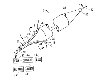
Figure 1 is a perspective view of a device having features of the
present invention;
Figure 2 is a perspective view of a second embodiment of a device
having features of the present invention;
Figure 3 is a side cut-away view taken on line 3-3 and positioned in a
vessel;
Figure 4A is a side cut-away view taken on line 4-4 of Figure 1 with a
positioner in a first configuration;
Figure 4B is a cut-away view taken of line 4-4 of Figure 1 with the
positioner in a second configuration;
Figure 5A is a side cut-away view of a third embodiment of a device
having features of the present invention with a positioner in a first
configuration;
4
CA 02282013 1999-09-09
Figure 5B is a side cut-away view of the embodiment of Figure 5A with
the positioner in a second confirmation;
Figure 6A is a side cut-away view of another embodiment of a device
having features of the present invention positioned in a portion of an vessel;
Figures 6B is an enlarged view of a portion of the device of Figure 6A;
Figure 7A is a perspective view, in a partial cut-away, of another
embodiment of the present invention;
Figure 7B is an enlarged cut-away view taken of line 7B-7B in Figure
7A;
Figure 8A is a perspective view of another embodiment of the present
invention;
Figure 8B is an enlarged illustration of another embodiment of the
present invention;
Figure 8C is an enlarged illustration of yet another embodiment of the
present invention; and
Figure 9 illustrates a side cut-away view of a balloon catheter
positioned in a vessel.
DESCRIPTION
The present invention is a device 10 and method which are particularly
suited for locating unstable, inflamed plaque 12 on a vessel wall 14 of a
vessel16. In the embodiment illustrated in Figure 1, the device 10 includes at
least one receiver 18, at least one carrier 20, a sensor 22, a catheter 24,
and
a positioner 26. The temperature of the inflamed plaque 12 is elevated
approximately 0.5 to 2.5 degrees Centigrade or Celsius. The present device
10 locates the unstable, inflamed plaque 12 by measuring the temperature of
the vessel wall 14 as the device is moved through vessel 16 and locating
areas of elevated temperature.
In the embodiment illustrated in the Figures 1-5, each receiver 18
receives information, i.e. infrared radiation, from the vessel wall 14 and
each
5
CA 02282013 1999-09-09
receiver 18 is an aperture proximate a carrier distal end 28 of each carrier
20
which exposes the carrier 20 to the vessel wall 14. Alternately for this
embodiment, for example, each receiver 18 can be a projection (not shown)
which extends between the vessel wall 14 and the carrier 20.
As illustrated in Figure 1, the device 10 can include a plurality of
spaced apart receivers 18 positioned circumferentially around the positioner
26 so that the temperature can be monitored around the circumference of the
vessel wall 14. For this embodiment, the sensitivity of the device 10
increases as the number of receivers 18 increases, because small inflamed
plaque 12 is less likely to pass between the receivers 18. In the
embodiments shown in the Figures 1-4, the device includes four,
circumferentially, spaced apart receivers 18. Importantly, the positioning of
the receivers 18 on the positioner 26 can vary. For example, as shown in
Figures 5A and 5B the device 10 can also include a plurality of receivers 18
spaced apart axially along the positioner 26 for additional sensitivity. Also,
the receivers 18 can be staggered along the positioner 26.
In the embodiment illustrated in Figures 1-4, each receivers 18 is
located above the surface of the positioner 26. Alternately, for example, each
receiver 18 may be located on, within or beneath the surface of the positioner
26.
The carrier 20 transfers the information from each receiver 18 to the
sensor 22. In the embodiments shown in the Figures 1-5, each receiver 18
includes a separate carrier 20 for transferring infrared radiation to the
sensor
22. As provided herein each carrier 20 can be an optical fiber having an
aperture at the carrier distal end 28 which forms each receiver 18. As shown
in phantom in Figure 1, a carrier proximal end 30 of each carrier 20 is
attached to the sensor 20. For this embodiment, any optical fiber which
transmits infrared radiation should make a suitable carrier 20.
The carrier 20 can be secured to the catheter 24 and positioner 26 in a
number of alternate ways. For example, in the embodiment shown in Figures
1, 3, 4A and 4B, the carriers 20 are positioned and secured to an outer
surface 32 of the catheter 20 and the positioner 26. Alternately, in the
6
CA 02282013 1999-09-09
embodiment shown in Figure 2, the carrier 18 can extend through apertures
in the positioner 26. In yet another embodiment shown in Figures 5A and 5B,
the carrier 20 can extend through a first lumen 32 of the catheter 24 and
through the positioner 26.
Preferably, the device 10 includes a marker 36 positioned proximate
each receiver 18 so that the location of each receiver 18 can be determined.
For example, each marker 36 can be a radiopaque material, such as silver
which is deposited on each carrier 20 proximate each receiver 18. In this
version, the position of the radiopaque marker 36 is visible with x-rays and a
fluoroscope.
The sensor 22 receives the information from each receiver 18 through
each carrier 20 and determines temperature at each receiver 18 based upon
the information received or determines if a change of temperature occurs at
each receiver 18. Preferably, the sensor 22 receives information from a
plurality of receivers 18 and determines the temperature or a temperature
difference at each receiver 18. For the embodiment illustrated in Figure 1,
the sensor 22 may be any suitable infrared radiation sensor. For example, a
sensor 22 made with a suitable pyroelectrical material can be utilized. As is
well known to those skilled in the art, pyroelectric material generates an
electric charge that is related to the amount of temperature change in the
pyroelectric material.
The sensor 22 can include a monitor 40, a comparator 42 and an
indicator 44. The monitor 40 displays and/or records the temperature at each
receiver 18 for review as the device 10 is moved in the vessel 16. The
comparator 42 compares the temperature between the receivers 18 to
determine whether a temperature difference exists between the receivers 18.
Further, the comparator 42 also compares the temperature at each receiver
18 to determine whether a temperature change occurs at each receiver 18 as
the device 10 is moved in the vessel.
The indicator 44 is connected to the comparator 42 and notifies the
user of the device 10, i.e., a surgeon, when the temperature difference
between each receiver 18 or the temperature change exceeds a
7
CA 02282013 1999-09-09
predetermined value. For example, if the temperature difference or the
temperature change is above the predetermined value, e.g., approximately
0.5-2.5 degrees Centigrade or Celsius, the indicator 44 will notify the user.
The indicator 44 can be implemented in a number of alternate ways, such as,
an audio signal, i.e., a bell, or a visual signal, i.e., a digital readout.
The catheter 24 can be used to position the positioner 26 and the
receivers 18 in the proper location in the vessel 16. Typically, the catheter
24
is cylindrical or elongated shaped and has a catheter distal end 46 which is
inserted into the vessel 16 and a catheter proximal end (not shown) which is
outside the vessel 16 for manipulating the catheter 24 in the vessel 16.
Preferably, the catheter 24 is formed from a flexible and somewhat stiff
material such as PET to facilitate movement through the vessel 10.
The design of the catheter 24 varies according to the design of the
expander 26. For example, the catheter 24 can include the first lumen 34 (as
discussed previously) and a second lumen 50. Referring to Figure 3, the first
lumen 34 can carry a guidewire 52 for guiding the catheter 24 in the vessel
16 or as shown in Figures 5A and 5B can retain the carriers 20. As
discussed below, the second lumen 50 can facilitate movement of the
positioner 26 between a first configuration 54 (shown in Figure 4A) and a
second configuration 56 (as shown in Figure 4B).
The positioner 26 positions the receivers 18 proximate the vessel wall
14. Further, some of the positioners 26 provided herein can also be used to
dilate the vessel 16. In the embodiments illustrated in Figures 1-5, the
positioner 26 is an expander which moves between the first configuration 54
for insertion into the vessel 16 and the second configuration 56. As shown in
Figures 1-4, the positioner 26 can be an inflatable balloon attached proximate
to the catheter distal end 28. Referring now to Figure 3, fluid (not shown)
may pass from a pressurized fluid source (not shown) through the second
lumen 50 and a balloon aperture 58 in the second lumen 50 to selectively
inflate the expander 26. Inflation of this nature may be appreciated by
comparison of Figure 4A, where the balloon is shown in the first configuration
54, and Figure 4B, where the balloon is shown substantially in the second
8
CA 02282013 1999-09-09
configuration 56. For the purposes of the present invention, numerous
devices, e.g., pumps or syringes may be adapted to function as a source of
fluid pressure.
It may be seen in Figure 3, that when the positioner 26 moves towards
its second configuration 56, each receiver 18 contacts the vessel wall 14. It
may be appreciated that the positioner 26 may be expanded more or less
than the expansion shown in Figure 3.
Alternate embodiments of the positioner 26 are also possible. For
example, as shown in Figures 5A and 5B, the positioner 26 can be a
cylindrical sleeve that is attached to the catheter distal end 46. The
cylindrical sleeve is preferably formed from a wire mesh and has a sleeve
distal end 60 and a sleeve proximal end 62. The sleeve proximal end 62 is
attached to the catheter distal end 46. A grommet 64 is attached to the
sleeve distal end 60. An actuator wire 66 can pass through the second
lumen 50 and connect to the grommet 64.
In this embodiment, the guidewire 52 extends through a positioning
guidewire lumen in the actuator wire 66. The actuator wire 66 is movable
within the second lumen 50 to cause the grommet 64 to move translationally.
Translational movement of the grommet 64 moves the sleeve distal end 60
translationally towards, or translationally away from, the catheter distal end
46. Movement of this type may be visualized by comparison of Figure 5A and
Figure 5B. In particular, it may be seen in Figure 5A that cylindrical sleeve
has a shorter overall length and increased overall width over the cylindrical
sleeve illustrated in Figure 5B. In this fashion, the actuator wire 66 may be
manipulated to selectively expand the cylindrical sleeve.
The device 10 can also include at least one flow passageway 70 which
allows for the flow of fluids, e.g., blood past the expander 26 when the
expander 26 is proximate the second configuration 56. Referring to Figure 3,
the flow passageway 70 can include a first port 72 and a second port 74
which are in fluid communication with the first lumen 34 and the vessel 16 on
each side of the expander 26.
9
CA 02282013 1999-09-09
Alternately, in the embodiment shown in Figures 5A and 5B, a series
of apertures (not shown) can be formed in the grommet 64 which allows for
the passage of fluid, e.g., blood past the expander 26. In yet another
embodiment, the expander 26 can be ribbed (not shown) or include grooves
(not shown) which form the flow passageway 70 and allow for the flow of
blood past the expander 26.
Preferably, the device also includes a heat source 26 which can be
connected to the carriers 20 for heating the inflamed plaque 12. In certain
situations, it is desirable to treat inflamed plaque 12 with heat. Therefore,
the
present invention allows the inflamed plaque 12 to be treated almost
immediately. The amount of heat which can be applied to the plaque 12 can
vary. It is anticipated that a heat source 26 which supplies sufficient heat
through the carriers 20 to heat the vessel wall 14 to about 40-45 degrees
centigrade is desirable.
Additionally, referring to Figure 2, the positioner 26 can also include
one or more fluid passageways 78 having opening 80 for delivering fluid
medications to the inflamed plaque 12. This allows positioner 26, for
example to immediately apply medications to the inflamed plaque 12 which
can seal the inflamed plaque 12, thereby inhibiting erosion or rupture. An
inflatable balloon having delivery conduits is disclosed in U.S. Patent No.
5,336,178, Kaplan et al. which is incorporated herein by reference.
Further, it is anticipated that the positioner 26, in some instances, can
be expanded to preform angioplasty or deliver a supporting stent (not shown)
if necessary.
In an alternate embodiment illustrated in Figures 6A-6B, the positioner
26 can be a positioning guidewire 82. In this embodiment, one or more
receivers 18 can be attached directly to the positioning guidewire 82. More
specifically, the receivers 18 are secured on a movable section 84 near a
distal end 86 of the positioning guidewire 82. The movable section 84 can be
maneuvered so that the receivers 18 contact the vessel wall 14. Figure 6A
illustrates the positioning guidewire 82 operationally positioned within the
vessel 16 of a patient 88. In this embodiment, a guiding catheter 90 is used
CA 02282013 1999-09-09
to extend through the patient 88 into the vessel 16. In the embodiment
illustrated, the movable section 84 is a bend in the positioning guidewire 82.
The movable section 84 is maneuvered through the guiding catheter 90 into
the vessel 16. Subsequently, a proximal end 92 of the positioning guidewire
82 is maneuvered and/or torqued until the movable section 84 is near or in
contact with the vessel wall 14. In this position, the receivers 18 can detect
the temperature at the vessel wall 14. Subsequently, the information can be
transferred from the receivers 18 to the sensor 22.
Figure 6B illustrates an enlarged view of the movable section 84. In
this embodiment, a pair of receivers 18 are secured to the movable section
84 while a carrier 20 transfers the information from the receivers 18 to the
sensor 22. Similar to the embodiments described above, each carrier 20 can
be an optical fiber having an aperture which forms the receiver 18. The
carrier 20 can transfer infrared radiation to the sensor 22. The carrier 22
illustrated in Figure 6B extends through a center of the positioning guidewire
82. Alternatively, the carrier 22 can run along an outer surface of the
positioning guidewire 82 and be attached with an epoxy or shrink wrap (not
shown). Further, any number of receivers 18 can be attached to the
positioning guidewire 82.
In yet an alternate embodiment illustrated in Figures 7A-7B, the device
10 includes the positioner 26, i.e. an inflatable balloon and a catheter 24
having a first lumen 34 and a second lumen 50. In this embodiment, the
receiver 18 includes a coating 94 which coats the positioner 26 and an
optical fiber 96 positioned in the first lumen 34. The coating 94 preferably
includes a luminescent material such as magnesium germinate or
magnesium flourogermanate activated with tetravalent manganese. A more
detailed description of the luminescent material can be found in U.S. Patent
No. 4,652,143, the contents of which are incorporated herein by reference.
The coating 94 can be positioned around a portion or the entire
circumference of the balloon. The coating 94 is subsequently positioned near
or in contact with the vessel wall 14. In this embodiment, light can be
emitted
from the optical fiber 96 positioned within the coating 94. The vessel wall 14
11
CA 02282013 1999-09-09
excites the luminescent material in the coating 94 and causes the
luminescent material to emit radiation with characteristics that are
proportional to the temperature of vessel wall 14. Subsequently, the optical
fiber 96 receives the information from the luminescent material and transfers
the information to the sensor 22. From this information, the sensor 22 is able
to determine the presence of inflamed plaque 12. Alternately, for example,
separate optical fibers (not shown) can be used to illuminate and receive
information in this embodiment.
In still another embodiment illustrated in Figures 8A-8C, the device
utilizes sound waves to locate the inflamed plaque. More specifically, the
device 10 utilizes ultrasound to plot or make thermal measurements of the
vessel wall 14. In particular, the speed of sound is modified by the
temperature of the medium through which the sound waves are directed.
Thus, the sound waves can be used to determine a temperature profile for
the vessel 16 and/or locate areas with higher temperatures. With this
information, the inflamed plaque 12 can be located along the vessel 16.
In this embodiment, the device 10 includes the positioner 26 and one
or more receivers 18. The positioner 26 is a shaft which carries the receivers
18. In the embodiment illustrated in Figures 8A-8C, each receiver 18 is a
transducer which produces sound waves from a voltage signal.
Subsequently, the sound waves are received by the transducer to produce an
electrical signal. Subsequently, the electrical signal is transferred to the
sensor 22 to establish a temperature profile for the vessel 16. A suitable
transducer is made of crystal such as P2T (lead zirconate-tifanate).
Alternately, for example, separate transducers could be used for producing
and receiving the sound waves.
Three versions of this sound wave embodiment are illustrated in
Figures 8A-8C. More specifically, in Figure 8A, the device 10 includes a
plurality of spaced apart receivers 18 which are positioned near a distal end
98 of the positioner 26. Alternately, the embodiment in Figure 8B, the device
10 includes a single receiver 18 which is rotated by a receiver motor 100
which is coupled to the receiver 18 with a drive shaft 102. In the alternate
12
CA 02282013 1999-09-09
embodiment illustrated in Figure 8C, the device 10 includes a single receiver
18. However, in this embodiment, a mirror 104 is rotated by a mirror motor
106 which is coupled to the mirror 104 with a mirror drive shaft 106. This
allows for the collecting of information around the circumference of the
vessel
16. Those skilled in the art will recognize alternate designs for the device
10
which utilizes ultrasound to located inflamed plaque 12. A more complete
discussion of ultrasound is provided in the book entitled, Intravascular
Ultrasound, R. Erbel, JRTC Roelandt, J Ge, G Gorge, eds. Martin Dunitz,
London 1998, the contents of which are incorporated herein by reference.
Importantly, the device 10 is able to evaluate whether plaque is
inflamed and unstable. The inflamed and unstable plaque 12 is subject to
rupture and/or ulceration which can cause the patient to experience a
myocardial infarction. Figure 9 illustrates a balloon catheter 108 positioned
in a vessel 16 adjacent to inflamed plaque 12. In this embodiment, after the
inflamed plaque 12 is located by device 10 (not shown in Figure 9), the
balloon catheter 108 is used to treat the inflamed plaque 12. Thus, the
balloon catheter 108 is used to treat the inflamed plaque 12 after it is
located
with the device 10. During treatment, the balloon catheter 108 dilates the
vessel and induces injury and/or ruptures the inflamed plaque 12. This
treatment can prevent subsequent rupture of the inflamed plaque 12.
OPERATION
The operation of one embodiment of the present invention, is best
appreciated with reference to Figures 1 and 3, and begins with insertion of
the guidewire 52 into the vessel 16. Next, the device 10 is inserted into the
vessel 16 over the guidewire 52, with the positioner 26 in substantially its
first
configuration 54. The advancement of the device 10 will continue until the
positioner 26 is at the position where testing of the vessel 16 is to begin.
Next, the positioner 26 is moved from its first configuration 54 toward
its second configuration 56. If the positioner 26 is a balloon, fluid is
supplied
13
CA 02282013 1999-09-09
under pressure through the second lumen 50 to inflate the balloon. The
expansion of the positioner 26 functions to move the receivers 18 to contact
the vessel wall 14.
Once the receivers 18 are against or near the vessel wall 14, the
plurality of receivers 18 begin receiving information from the vessel wall 14.
The information is transmitted through the carriers 20 to the sensor 22. The
sensor 22 receives the information and determines the temperature at each
receiver 18. The monitor 40 displays and/or records the temperature at each
receiver 18. The comparator 42 compares the temperature at the receivers
18 to determine if a temperature difference exists between the receivers 18.
If the temperature difference exceeds the predetermined value, the indicator
44 notifies the user of the device 10 and the inflamed plaque 12 is located.
Next, the positioner 26 is returned to its first configuration 54 for
movement to a different site and then returned to proximate its second
configuration 56, with the receivers 18 proximate the vessel wall 14.
Alternately, depending upon the design of the positioner 26, the positioner 26
may be moved in the vessel 16 with the receivers 18 proximate the vessel
wall 14.
As the receivers 18 are moved in the vessel 16, the sensor 22
continues to determine the temperature at each receiver 18 and the
comparator 42 continues to determine whether a temperature difference
exists between the receivers 18. Further, during this time, the comparator 42
compares the temperatures to determine if a temperature change occurs at
any of the receivers 18. Again, if the temperature difference or the
temperature change exceeds the predetermined value, the indicator 44
notifies the user of the device 10.
It is important to recognize that the positioner 26 can be moved
between its first and second configurations 54, 56 as necessary to facilitate
movement of the device 10 through the vessel 16 and to keep the receivers
18 proximate the vessel wall 14.
14
CA 02282013 1999-09-09
It is also important to recognize that the size of the inflamed plaque 12
can also be determined from the temperatures as the device 10 is moved
through the vessel 16.
Further, it is anticipated that the present device 10 can be used in
conjunction with existing procedures such as angiography to precisely locate
inflamed plaque 12.
While the particular device 10 as herein shown and disclosed in detail
is fully capable of obtaining the objects and providing the advantages herein
before stated, it is to be understood that it is merely illustrative of the
presently preferred embodiments of the invention. Therefore, no limitations
are intended to the details of construction or design herein shown other than
as described in the appended claims.