Note: Descriptions are shown in the official language in which they were submitted.
CA 02282045 1999-08-30
MP-1990
IMPROVED LIGHT HARNESS
BACKGROUND OF THE INVENTION
This invention relates to the art of exterior lighting for vehicles and, more
particularly, to an
auxiliary light and wiring arrangement for connecting the auxiliary light to a
vehicle.
The present invention finds particular utility in connection with vehicles
such as snow plows
$ having an attached plow blade and, accordingly, is disclosed and described
in detail hereinafter in
connection with such use. However, it will be appreciated that the invention
is applicable to other
lighting and electrical connection uses.
Auxiliary lights are light sources utilized to supplement a vehicle's standard
lighting. These
lights are often used, for example, on snowplow vehicles and on off road
vehicles. The lights for
these uses are designed to either mount on the frame of a snow plow or some
other external
component of the vehicle capable of supporting the light. Although the use of
auxiliary lights is
becoming popular for various types of vehicles and vehicle applications, the
type of available lights
and the wiring harness used to connect these auxiliary to the vehicle's
existing electrical system have
many inherent problems.
Existing auxiliary light designs commonly utilize a conventional sealed beam
headlight
within the auxiliary light housing assembly. Due to the size and weight of the
conventional sealed
beam auxiliary lights, such auxiliary lights are undesirably heavy, thereby
requiring stronger and
costlier housing materials and/or reinforcement of the components in the
auxiliary light housing.
These heavy auxiliary lights also limit the mounting locations on a vehicle
and can result in
increased incidents of damage to the light and/or vehicle when the vehicle is
operated in harsh and/or
off road environments. Another problem with existing auxiliary lights is the
design of such lights
and the difficultly in replacing parts. Replacement of a sealed beam headlight
varies in difficulty
based on the structure, age and condition of the auxiliary lighting assembly.
The removal of the
cover plates and support thereof is difficult and time consuming. Dismounting
of the auxiliary light
can also be difficult since such lights do not include integral mounting
components, thereby
-1-
~CA 02282045 2002-O1-11
MP-x990
requiring an additional support member, a bezel, and/or other components to
secure the light to~the
housing. The auxiliary lights typically include pads which provide cushioning
and reduce vibration
of the light components. The location and number of components of the
auxiliary light make it
difficult to access, remove, replace and reseal the auxiliary light
components. Many of the problems
associated with auxiliary lights are addressed and overcome by the improved
auxiliary light.
disclosed in United States'Design Patent No. 399,326 of October 6, 1998 and
United States Patent
No. 6,015,219 issued January' 18, 2000.
The wiring arrangements or harnesses for auxiliary light systems also have
many problems.
Traditionally, the auxiliary lights were spliced inta the existing wiring for
the headlights of the
vehicle. The splicing of the existing wiring caused many problems. Wires which
were not properly
spliced together become loose resulting in the auxiliary lights and/or
headlights to malfunction.
Improperly spliced wires also resulted in electrical shorts which could
damaged the electrical system
of the vehicle and/or cause a malfunction with one or more electrical systems
of the. vehicle,
including the headlights and/or auxiliary lights. The splicing of OEM wiring
of.the vehicle further
resulted in the voiding of many of the warranties for the OEM wiring of the
vehicle and/or headlights
of the vehicle. The splicing of the auxiliary light system into the existing
electrical system of the
vehicle further made it difficult to connect and disconnect the auxiliary
lights when the auxiliary
lights needed to be repaired or were not needed. Such connecting and
disconnecting also resulted
in increased wear and damage to the spliced region of the vehicle electrical
system thereby resulting
in increased incidents of failure or malfunction of the vehicle electrical
system.
In view of the problems associated with splicing auxiliary lights to the
existing electrical
system of a vehicle, auxiliary light harnesses were developed to eliminate the
need to splice the
OEM wiring to the headlights of a vehicle. One such electrical harness is
disclosed in United States
Letters Patent No. 4,280,062 issued to Richard R: Miller. The Miller harness
connects the headlights
of a vehicle and two auxiliary lights to a single existing vehicle plug that
is connected to a vehicle
headlight power source. The Miller harness requires the existing headlight
wiring harness to be
disconnected prior to using the harness. Therefore, when using the Miller
harness, a portion of the
-2-
CA 02282045 1999-08-30
MP-1990
OEM wiring of the vehicle is not used and can be discarded. Although the
Miller harness overcomes
some of the problems associated with splicing OEM wiring for the headlights of
the vehicle, several
problems exist when using the Miller harness.
The Miller harness is designed to connect two basic auxiliary lights to a
vehicle's headlight
power source. The Miller harness cannot be used with auxiliary lights that
house emergency and/or
turning signal lights along with the beam light. Consequently, the Miller
harness is limited for use
with only certain type of auxiliary lights. The Miller harness is designed to
provide power to the
vehicle headlights and/or the auxiliary lights from a single vehicle headlight
power source. The
current drawn on the single vehicle headlight power source during the
operation of both headlights
and/or auxiliary lights can result in an overload and/or damage to the wiring
of the single vehicle
headlight source caused by too much current being drawn through the wiring.
The Miller harness,
during installation, requires a cable containing at least six wires to be
inserted through the fire wall
of the vehicle so that a six pole switch can be mounted on or near the
dashboard of the vehicle. Due
to the large number of wires, a large hole must be drilled through the fire
wall of the vehicle. Such
1 S size a hole can be difficult to form in the fire wall and can result in
damage to the vehicle. The
switch used in the Miller harness required six or more wires to be connected
in a certain arrangement
for the switch to operate properly. Improper connection of the wires to the
switch results in a short
in the harness which could cause damage and/or malfunction to the electrical
system of the vehicle
and/or damage to the headlights and/or auxiliary lights. In addition, due to
the multiple wires
connected to the switch of the Miller harness, it is difficult to locate a
damaged or faulty wire to the
switch and/or replace a wire to the switch. Shorting of the electrical system
of the Miller harness
and/or vehicle electrical system can occur during the use of the Miller
harness. VYhen using the
Miller harness, only one of the vehicle headlight power sources is connected
to the harness. The
other vehicle headlight power source remains disconnected. During the
operation of the vehicle,
moisture, dirt, etc. can collect in the unused headlight power source and can
cause a short during the
operation of the vehicle. Furthermore, when the auxiliary headlights are
disconnect from the Miller
harness and the harness is not removed from the vehicle, the connectors for
the auxiliary lights can
-3-
CA 02282045 1999-08-30
MP-1990
collect moisture, dirt, etc. which can cause a short during the operation of
the vehicle. The Miller
harness also cannot be partially or totally detached and reattached in the
vehicle without significant
difficulty. When the Miller harness is to be repaired and requires the
repaired portion to be removed .
from the vehicle, the complete harness must be removed from the vehicle. This
requires the multiple
wires to the switch to be pulled through the vehicle fire wall and out of the
engine compartment
without damaging the wires. When the Miller harness is to be reattached to the
vehicle, the multiple
wires must be inserted through the fire wall without damaging the wires and
properly reattached to
the switch.
In view of the deficiencies of prior auxiliary light harnesses, there is a
need for an auxiliary
light harness that can be used with a wide variety of auxiliary lights, which
eliminates the need to
splice the wiring to the headlights of a vehicle, which is easy to install in
a vehicle, which reduces
the occurrences of overloading the OEM wiring of the vehicle, which protects
against shorting of
an electrical circuit, which one or more components of the harness can be
easily detached and
reattached to the vehicle, and which components of the harness can be easily
accessed for easy repair
and/or replacement.
SUMMARY OF THE INVENTION
An auxiliary light harness in accordance with the present invention overcomes
the foregoing
and other problems heretofore encountered in connection with the use of prior
auxiliary light
harnesses. The auxiliary light harness incorporates a simple modular design
that simplifies the
installation of the auxiliary light harness and improves the safety and
reliability of-the auxiliary
harness.
In accordance with a principle feature of the present invention, there is
provided an auxiliary
light harness for connecting auxiliary headlights such as snow plow lights to
the OEM wiring of a
vehicle and will be describe with particular reference thereto; however, the
invention has broader
applications and can be use to connect many types of auxiliary electrical
systems and lights to the
OEM wiring of a vehicle, aircraft, boat, train, trailer, building, etc.
In accordance with another feature of the present invention, the auxiliary
light harness
-4-
CA 02282045 1999-08-30
MP-1990
includes electrical connectors designed to connect to the OEM wiring of a
vehicle headlight and to
the OEM wiring for the power source of the vehicle headlight. The vehicle
headlights include a
connector which can be attached to the power source of a vehicle. The
auxiliary light harness of the
present invention is designed to have two connectors whereby one of the
connectors is connected
to the vehicle headlight, and the other connector is connected to the power
source to which the
vehicle headlight was originally attached. Consequently, the auxiliary harness
design utilizes all of
the OEM wiring of a vehicle and none of the OEM wiring of the vehicle is
discarded or only
partially utilized when the auxiliary light harness is attached to the
vehicle.
In accordance with still another feature of the present invention, the
auxiliary light harness
is designed to be integrated with the fuming signals andlor emergency lighting
of the vehicle. In this
regard, auxiliary headlights which are attached to the vehicle and include
turn signals and/or
emergency lighting can be attached to the auxiliary harness so that such
turning signals and/or
emergency lights are activated when the operator of the vehicle activates such
turning signals and/or
emergency lights. As a result, the auxiliary light harness can connect a
variety of auxiliary lights
to the vehicle.
In accordance with still another feature of the present invention, the
auxiliary light harness
includes circuitry which reduces the complexity of installation, operation,
maintenance and repair
of the auxiliary light harness. In one preferred design, the auxiliary light
harness includes solid state
circuitry which controls the activation and deactivation of the auxiliary
lights. The solid state
circuitry increases the reliability of the auxiliary light harness circuitry
and reduces the number of
wires needed to connect the auxiliary light harness to the OEM wiring of the
vehicle. The solid state
circuitry also reduces the number of wires which must be threaded through the
fire wall of a vehicle
into the auxiliary lighting switch located in the operator driving
compartment. The reduced number
of wires needed for the switch and the overall circuitry of the auxiliary
light harness greatly
simplifies the installation, maintenance, reliability and repair of the
auxiliary light harness.
In accordance with still yet another feature of the present invention, the
auxiliary lift
harness is designed to be a modular unit which allows the auxiliary lights to
be easily detached and
-5-
CA 02282045 1999-08-30
MP-1990
removed from the vehicle without having to dismantle and remove the complete
auxiliary light
harness from the vehicle. This modular design of the auxiliary light harness
also allows for
components of the auxiliary light harness to be easily removed and replaced
when in need of repair
or replacement without having to completely remove or dissemble the auxiliary
light harness from
the vehicle.
In accordance with another feature of the present invention, the auxiliary
light system is
connected to the vehicle power source in a manner as to reduce the occurrences
of the auxiliary
lights inadvertently draining the power of the vehicle's battery. Preferably,
the auxiliary light
harness is connected in series to the ignition switch of the vehicle such that
the ignition switch must
be activated prior to the auxiliary lights being activated. When the ignition
switch of the vehicle is
activated, the vehicle's engine is typically running, thereby supplying
sufficient power to the vehicle.
During the operation of the engine, the activation of the auxiliary light
system can be activated
without draining the battery power of the vehicle.
In accordance with still yet another feature of the present invention, the
auxiliary light
harness can be designed to allow the vehicle's headlights or the auxiliary
lights of the vehicle to be
activated; or allow both the auxiliary lights and the headlights of the
vehicle to be activated. When
the auxiliary light harness is used to attach snowplow lights to a vehicle,
the headlights of the vehicle
are typically deactivated when the snowplow lights are activated since the
snowplow blade typically
obstructs the light from the headlights. Therefore, it is desirable to
deactivate the headlights of the
vehicle upon activation of the plow lights so as to preserve the life of the
vehicle headlights. In other
applications wherein the auxiliary lights are fog lights, it is desirable to
have both the fog lights and
the headlights simultaneously activated to increase the number of lumens
generated by the vehicle.
In accordance with another feature of the present invention, the auxiliary
light harness
incorporates special connectors to ensure that the connectors will not
inadvertently become
disconnected during operation. Preferably, the connectors include a lock
system such as a snap lock,
which ensures that the connectors are properly secured together and to further
prevent the
connections from loosening or becoming disconnected during the operation of
the vehicle. The
-6-
CA 02282045 1999-08-30
MP-1990
connectors are also preferably designed to allow the connectors to be
connected in only one manner,
so as to prevent an improper connection. In this manner, the connectors are
specially shaped so that
the connectors can only be attached together in one manner.
In accordance with yet another feature of the present invention, the auxiliary
light harness
includes a seal arrangement to prevent foreign materials from damaging and/or
causing a short in
the circuitry of the auxiliary light harness. Preferably, the connectors
utilized in the auxiliary light
harness include seals that inhibit and/or prevent liquid, dust, dirt and/or
other debris from contacting
the electrical connections of the auxiliary light harness. In one preferred
design, the connectors
include rubber, plastic, and/or Teflon seals to prevent foreign materials from
interacting with the
electrical connections of the vehicle light harness. The seals help prevent
corrosion of the electrical
connections, bad connections between the electrical connections, shorting of
the electrical
connections and the like.
In accordance with another feature of the present invention, the connectors
include plugs
which are utilized when the auxiliary lights are disconnected and removed from
the vehicle. After
the auxiliary lights are disconnected from the auxiliary light harness, the
electrical connectors of the
auxiliary light harness are exposed to the environment. The connector plugs
are designed to connect
to the ends of these electrical connections to seal the electrical connections
from the environment,
thereby inhibiting and/or preventing con:osion of the electrical connections,
and/or other debris from
depositing on the electrical connections which may impair the operation of the
auxiliary light harness
when the auxiliary lights are once again attached to the harness. Preferably,
these plugs are also used
for the ends of the connectors on the auxiliary light harness that connect to
the auxiliary light
connectors so as to also prevent corrosion and/or debris depositing on and/or
in the electrical
connections while the auxiliary lights are being stored.
It is accordingly a principal object of the present invention to provide an
improved auxiliary
light harness to be used in conjunction with a vehicle which is simple to
install and operate.
Another object of the present invention is the provision of an auxiliary light
harness which
can be used with a wide variety and style of auxiliary lights.
CA 02282045 1999-08-30
MP-1990
Still another object of the present invention is the provision of an auxiliary
light harness
which utilizes the OEM wiring of a vehicle headlight system without the need
to splice the OEM
wiring to the vehicle headlights.
Yet another object of the present invention is the provision of an auxiliary
light harness
which utilizes all of the OEM wiring for the headlight system of a vehicle.
Still yet another object of the present invention is the provision of an
auxiliary light harness
which reduces the occurrence of overloading the OEM wiring of the vehicle
during the operation of
the auxiliary lights.
Another object of the present invention is the provision of an auxiliary light
system which
protects against the shorting and/or damage of the electrical system of the
auxiliary light harness.
Still another object of the present invention is the provision of an auxiliary
light harness
which allows for one or more of the components of the harness to be easily
attached and reattached
to the vehicle without having to substantially remove the harness from the
vehicle.
Yet another object of the present invention is the provision of an auxiliary
light system which
1 S can be easily maintained and repaired.
Still yet another object of the present invention is the provision of an
auxiliary light system
which reduces the occurrences of the components of the harness being
incorrectly connected
together.
Still a further object of the present invention is the provision of an
auxiliary light system
which reduces the occurrence of components becoming inadvertently disconnected-
during the
operation of the vehicle.
Another obj ect of the present invention is the provision of an auxiliary
light harness which
includes a modular design that simplifies the installation, repair,
maintenance and operation of the
auxiliary lights on a vehicle.
Yet another object of the present invention is the provision of an auxiliary
light harness
which reduces the occurrence of inadvertent power drain of a vehicle's battery
during the operation
of the auxiliary lights.
_g_
CA 02282045 1999-08-30
MP-1990
Yet still another object of the present invention is the provision of an
auxiliary light harness
which includes solid state circuitry to improve the reliability and simplicity
of operation,
maintenance, installation, and repair or the auxiliary vehicle light harness.
Another object of the present invention is the provision of an auxiliary light
harness that
S includes a sealing arrangement to reduce degradation of the electrical
circuitry and/or interface with
electrical connections.
These and other objects and advantages will become apparent from the following
description
used to illustrate the preferred embodiment of the invention when read in
conjunction with the
accompanying drawings.
BRIEF DESCRIPTION OF THE DRAWINGS
FIGURE 1 is a schematic view of the auxiliary light harness and components
attached thereto
in accordance with the present invention;
FIGURE 2 is an electrical schematic drawing of the auxiliary light harness
illustrated in
FIGURE 1;
FIGURE 3 is an electrical schematic drawing of a circuit used in the
electrical auxiliary light
harness in FIGURE 1;
FIGURE 4 is a electrical schematic drawing illustrating the circuit of FIGURE
3 controlling
one vehicle headlight and one auxiliary headlamp;
FIGURE 5 is a side elevation view of a connector and a connector plug in
accordance with
the invention;
FIGURE 6 is a cross sectional view along line 6-6 of FIGURE 5;
FIGURE 7 is a side elevation view of two connectors in accordance with the
invention;
FIGURE 8 illustrates the connectors in FIGURE 7 in a sealed arrangement;
FIGURE 9 is a front elevation view of the connectors to a circuit; and
FIGURE 10 is a cross sectional view along line 10-10 of FIGURE 9.
DESCRIPTION OF THE PREFERRED EMBODIMENT
Referring now to the preferred embodiment of the drawings, wherein the
showings are for
-9-
CA 02282045 1999-08-30
MP-1990
the purpose of illustrating a preferred embodiment of the invention only and
not for the purpose of
limiting the invention, FIGURES 1 and 2 are schematic drawings of the
auxiliary light harness 10
in accordance with the present invention. Auxiliary harness 10 is designed to
electrically connect
auxiliary lights 30 to the electrical system of a vehicle. As specifically
illustrated in FIGURES 1
and 2, auxiliary lights 30 are auxiliary headlights which are electrically
connected to the headlight
electrical circuitry of a vehicle.
In a typical vehicle, the vehicle includes two headlights 20 wherein each of
the headlights
includes wiring 22 which electrically connects to the light in the headlight
at one end and includes
a connector 24 at the other end. Headlight wire connector 24 is electrically
connected to the OEM
headlight wiring 100 of the vehicle. Specifically, connector 24 connects to
connector 102 of the
OEM headlight wiring. The vehicle also typically includes a turn/emergency
light 40 which has a
turn light 44 and an emergency light 46. Wiring 42 connects turn light 44 and
emergency light 46
to the OEM light wiring of the vehicle.
Auxiliary light harness 10 is designed to connect to the headlight wiring
connectors, turn and
emergency light wiring and to the OEM headlight wiring connectors. Once the
auxiliary light
harness 10 is properly connected to the electrical system of a vehicle, all
the OEM wiring to the
headlights of the vehicle is operational and used by the harness.
Referring specifically to FIGURE 1, the auxiliary light harness is connected
to the OEM
headlight wiring of the vehicle and to the turn light and emergency light
wiring of the vehicle. When
the auxiliary light harness 10 is installed, headlight wiring connector 24 is
disconnected from OEM
headlight wiring connector 102. Harness headlight wiring connector 62 is then
connected to the
headlight wiring connector 24. Furthermore, harness headlight power connector
64 is connected to
OEM headlight wiring connector 102. Connectors 62 and 64 are part of harness
headlight wiring
60 which connects to a harness control module S0. Harness headlight wiring 60
includes a port
connector 66 which connects to module headlight port 52 of control module 50.
~As illustrated in
FIGURE 1, each set of auxiliary light 30 and headlight 20 has its own harness
control module S0.
Typically, harness 10 will only include two harness control modules since most
vehicles typically
-10-
CA 02282045 2002-O1-11
IVfP-1990
have only two headlights. ..
Auxiliary light 30 includes auxiliary light wiring 32 which connects at one
end to the lights
in auxiliary light 30 and at the other end includes a wiring connector 34.
Wiring connector 34 is
connected to harness auxiliary light connector 72 which in turn is connected
to one end of harness
$ auxiliary light wiring 70. At the other end of auxiliary light wiring 70 is
a port connector 74 which
connects to auxiliary light port 54 of control module 50.
Turn light/emergency light 40 are electrically connected to OEM wiring.
Harness switch
wiring 80 includes two wires 86, 88 which connect to wiring 42 by connectors
90, 92. The electrical
connectors can take any form which creates an electrical connection between
turn/emergency light
wiring 42 and turn light wire 86 and emergency light wire 88. Preferably, the
connectors are
electrical splices. Harness switch wiring 80 is connected to include a port
connector 82 which
connects to module switch port 56 of control module 50. Harness switch wiring
80 also includes
a ground connection and switch wire 84.
As shown in FIGURE 1, the switch wires 84 from each of the two control modules
50 are
coilnected together by switch wire connector 110. The other end of switch wire
connector 110 is
connected to a switching wire 112 which terminates at one end of auxiliary
light switch 120.
The auxiliary headlights 30 can be a variety of different styles and types of
headlights. One
preferable type of auxiliary headlight is disclosed in the assignee's United
States Design Patent No.
399,326 of October 6, I99& and United States Patent No. 6,015,219 issued
January 18, 2000. The
manner in which the auxiliary headlights can be connected to the vehicle will
depend on the style
and type of the vehicle and the style and type of auxiliary headlight. One
preferable arrangement
for mounting the auxiliary headlight is disclosed in assignee's United States
Design and Utility Patents
No. 399,326 and 6,015,219, respectively.
As illustrated in FIGURE 1, control module 50 includes a module mount hole 58.
Mount
hole 58 is designed to allow the control modules to be secured in the interior
of a vehicle by bolts,
screws or the like. Preferably, the control module 50 is mounted near each
headlight of the vehicle.
As can be appreciated, the wiring for the electrical harness may be secured by
ties, clamps and the
-11-
CA 02282045 1999-08-30
MP-1990
like to ensure that the wiring is secured in place during the operation of the
vehicle.
Referring now to FIGURE 2, a more detailed diagram of how the headlights, turn
lights,
emergency lights, and auxiliary lights are electrically connected to auxiliary
wire harness 10 is
illustrated. In particular, auxiliary light switch 120 is connected in series
to the vehicle ignition
switch 140. By connecting the auxiliary light harness 10 in such fashion,
auxiliary lights 30 cannot
be activated before the ignition switch of the vehicle is engaged. This
connection arrangement is
different from the vehicle headlight switch 160 connection wherein headlights
20 can be activated
independently of the engagement of ignition switch 140. As can be appreciated,
auxiliary lights 30
are prevented from draining the power from the vehicle battery. This
arrangement is very beneficial
in that the auxiliary lights 30 typically draw substantially more power than
standard headlights, and
thus can drain a vehicle's battery in a substantially shorter time than the
vehicle's headlights.
However, after an operator activates the ignition switch of the vehicle
thereby causing the vehicle
engine to run, the power generated by the engine is more than sufficient to
power the auxiliary lights,
thus preventing the power drain of the vehicle battery by the auxiliary
lights.
Referring now to FIGURES 3 and 4, a more detailed electrical diagram of the
auxiliary light
harness 10 is illustrated. In FIGURE 4, a detailed electrical connection
arrangement for the switch
wire is illustrated. Switching wire 112 is shown to be connected to one end of
auxiliary light switch
120. The other end of auxiliary light switch 120 is connected by a light
switch wire 122 to a fuse
box 130 of a vehicle. The specific fuse selected is to be in series with
ignition switch 140 of the
vehicle so as to prevent current from passing through switching wire 112 until
both auxiliary light
switch 120 and ignition switch 140 are activated.
FIGURE 4 also illustrates a standard dimmer switch 162 connected in series
with headlamp
switch 160. Dimmer switch 162 is used to activate the low beam light 26 and
the high beam light
28 of headlight 20 and the low beam light 35 and high beam light 36 of
auxiliary light 30.
As illustrated in both FIGURES 3 and 4, control module 50 is designed to
activate the
auxiliary lights 30 and deactivate headlights 20 of a vehicle when auxiliary
light switch 120 and
ignition switch 140 are activated. When ignition switch 140 and/or auxiliary
light switch 120 are
-12-
CA 02282045 1999-08-30
MP-1990
deactivated, headlights 120 are automatically reactivated and auxiliary lights
30 are automatically
deactivated.
As shown in FIGURE 4, switch wire 84 receives current from power source 150
when both
ignition switch 140 and auxiliary light switch 120 are activated. Switch wire
84 transfers such
current to control module 50 through module switch port 56. Referring
specifically to FIGURE 3,
wire 464 is connected to switch wire 84 at module switch port 56. Wire 464 is
electrically connected
to three solid state switches 400, 420 and 440 contained in harness control
module 50. Specifically,
wire 464 is connected to switch controllers 406, 426 and 446 of solid state
switches 400, 420 and
440, respectively. The solid state switches illustrated in FIGURE 3 are
schematic representations
of any of a number of a type of solid state switches. Preferably, the solid
state switch is a transistor,
magnetic switch or similar electrical switching device. When current passes
through wire 464 and
into switch controllers 406, 426 and 446, the switch controllers cause switch
blades 404, 424 and
444 to connect to wires 456, 478 and 480, respectively. When current ceases to
pass through wire
464, switch controllers 406, 426 and 446 cause switch blades 404, 424 and 444
to move back into
their original positions so as to once again be engaged with wires 456, 458
and 460, respectively.
Referring to both FIGURE 3 and FIGURE 4, the operation of control module 50 of
auxiliary
light harness 10 will be briefly described. Auxiliary light harness 10 is
designed such that when
auxiliary light switch 120 and/or ignition switch 140 are not switched on, the
solid state switches
and control module 20 are in their initial contact position. In such a
position, the headlights 20 of
the vehicle operate in their standard manner, and the auxiliary lights 30 are
deactivated. In this mode
of operation, the headlights 20 of the vehicle operate in their standard
fashion along with the
operation of the turn/emergency lights 40 of the vehicle. When the operator
activates the ignition
switch 140 by turning on the vehicle and also activating auxiliary light
switch 120, which is typically
located in the driving compartment of the vehicle, current is directed through
switch wire 84 into
control module 50. The current passing through switch wire 84 in turn causes
the solid state
switches in the control module 50 to move to the activated position. In such a
position, the power
to the vehicle's headlights is rerouted to the auxiliary lights 30 of the
vehicle. This rerouting of
-13-
CA 02282045 1999-08-30
MP-1990
power causes the headlights of the vehicle to become deactivated and the
auxiliary lights 30 to
become activated.
As can be appreciated, when headlight switch 160 is deactivated, the
headlights 20 of the
vehicle are off, since no power is connected to the headlights. In addition,
when headlamp switch
160 is deactivated, the auxiliary lights 30 cannot be activated since
headlight switch 160 continues
the power flow through OEM wiring 100. Consequently, the auxiliary lights 30
cannot be activated
until headlight switch 160, ignition switch 140 and auxiliary switch 120 are
all activated at the same
time. The wiring of the control module 50 is designed such that the signal
caused by dimmer switch
162 is received by auxiliary lights 30 the same as when the headlights 20 are
activated.
Consequently, dimmer switch 162 controls the low beam light 35 and the high
beam light 36 of
auxiliary light 30 in a similar manner as when dimmer switch 162 controls the
low beam light 26
and the high beam light 28 of headlight 20. Auxiliary light harness 10 also
routes power from
turn/emergency light wiring 42 to auxiliary light 30. However, unlike the
circuitry between the
vehicle headlights and the auxiliary lights, auxiliary light harness 10 does
not deactivate the vehicle's
turn signals or the vehicle's emergency lights when the auxiliary lights are
activated. As shown in
the circuit diagrams of FIGURES 3 and 4, when the vehicle turn signal and/or
the vehicle emergency
light is activated, harness turn light wire 86 and harness emergency light
wire 88 route such signals
from turn/emergency light wiring 42 through harness control module 50 and into
auxiliary turn light
37 and auxiliary emergency light 38 of auxiliary 30 to thereby cause such
lights to activate
simultaneously with the vehicle's turn light 44 and/or emergency light 46.
Referring now to FIGURE 1, auxiliary light harness 10 has a modular design in
that the
various components can be connected, replaced, and/or repaired without having
to completely
dissemble and/or remove the harness from the vehicle. The solid state
construction of the control
module simplifies the wiring of the electrical harness, and ensures the
desired operation of the
headlights of the vehicle and the auxiliary lights of the vehicle occurs
during an emergency or some
unforeseen circumstance. The reduced number of wires through the fire wall of
the vehicle and into
the driving compartment of the vehicle also simplifies installation of the
harness, and simplifies and
-14-
CA 02282045 1999-08-30
MP-1990
reduces the time for maintenance and repair of the vehicle, and further
reduces unnecessary damage
to the vehicle. As shown in FIGURE 1, switching wire 112 is a single wire that
connects to switch
120. Consequently, only a small hole is needed through the fire wall of the
vehicle to connect switch
wire 112 to switch 120, thus significantly simplifying installation and repair
of the auxiliary light
harness. Switch 120 preferably includes an indicator, such as a light, to
notify a vehicle operator of
the position of switch 120. As can be appreciated, the majority of the wiring
of the harness, the
control modules and the harness and the switch of the harness can remain in
the vehicle from season
to season, even though the auxiliary lights are periodically removed,
reinstalled and/or replaced on
the vehicle. This can be accomplished by simply disconnecting auxiliary light
connector 34 from
harness auxiliary light wire connector 72 and dismounting the.auxiliary light
from the vehicle.
When the auxiliary light once again is to be reinstalled, connector 34 of the
auxiliary light is simply
reconnected to the harness auxiliary light connector 72.
The integrity of the auxiliary light harness 10 is maintained by several seals
which are
utilized at the connections with the control module and with the connection
between the auxiliary
light connector 34 and harness headlight connector 62. As can be appreciated,
a similar seal
construction can be created for harness headlight power connector 64 and OEM
light wiring
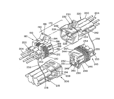
connector 102. Referring now to FIGURES 5-8, a seal connector 170 is
illustrated. Seal connector
170 includes a male connector 180 and a female connector housing 220. As best
shown in
FIGURES 6 and 7, male connector housing 180 includes a neck portion 182
designed to be
telescopically inserted into female connector housing 220. At the front end of
neck portion 182 is
a plurality of neck openings 183. Positioned inside of each of the neck
openings is a conductor
socket 184. Each conductor socket 184 is secured in place by a socket lock tab
185. Each conductor
socket includes a socket contact 186 designed to engage a conducting pin when
positioned in female
connector housing 220.
The neck portion 182 of male connector housing 180 includes one or more neck
ridges 188.
These neck ridges define a particular shape of the outer surface of the neck
portion so as to only
allow the neck portion to be inserted in one specific manner into female
connector housing 220 so
-15-
CA 02282045 1999-08-30
MP-1990
as to ensure the proper electrical connection between the male connector
housing 180 and the female
connector housing 220.
Neck portion 182 also includes a seal surface 189 which supports a seal 210.
Seal 210
includes a plurality of seal ribs 212. Seal 210 is designed to create a seal
between neck portion 182
of male connector housing 180 and female connector housing 220 when the neck
portion is
telescopically inserted into female connector housing 220. The seal prevents
and/or inhibits liquids,
dust, dirt and the like from coming into contact with the conducting sockets
184 in male connector
housing 180 and conductor pins 268 in female connector housing 220. The seals
inhibit and/or
prevent the conductor sockets and the conductor pins from corroding or
allowing foreign materials
to interfere with the electrical connection between the conducting sockets and
the conductor pins
when the male and female connector housings are connected together.
Positioned adjacent to the rear of neck portion 182 of male connector housing
180 is a lock
latch 190. Lock latch 190 includes two latch arms 192. Connected between the
two latch amls is
a latch handle 194. The latch handle 194 includes a handle bar 196 and a slot
198. Latch arms 192
are made of material which is flexible to allow the latch handle to be lifted.
The rear of male connector housing 180 includes a plurality of connector rear
openings 200.
The openings are sized to allow wire 204 to pass through the openings. Wire
seal 197 seals wire 204
within rear opening 200 so as to inhibit and/or prevent liquids, dust, dirt
and the like from entering
the rear opening and corroding and/or interfering with the electrical
connections with conducting
socket 184.
A security cable opening 202 is positioned adjacent to the rear openings of
the male
connector housing. Security cable opening 202 is designed to receive security
cable 258.
Connected to the other end of security cable 258 is male seal connector 206.
Male seal
connector 206 includes a connector cavity which is designed to receive neck
portion 182 and seal
210 on male connector housing 180. Inside connector cavity 208 is a
positioning cavity 214 which
is designed to allow neck portion 182 to be inserted into connector cavity 208
in only the proper
manner. Male seal connector 206 also includes a lock tab 215. Connected to
lock tab 215 is a tab
-16-
CA 02282045 1999-08-30
MP-1990
guide 216 and a tab landing 217. Male seal connector 206 also includes a
security cable opening 218
which receives the second end of security cable 258.
Female connector housing 220 includes a connector cavity 222 at the front of
the female
connector housing. Connector cavity 222 has a cross sectional shape and size
which is designed to
receive neck portion 182 of male connector housing 180. Within connector
cavity 222 is a
positioning cavity 224. Positioning cavity 224 is sized and shaped to
specifically telescopically
receive a portion of neck portion 182 such that male connector hosing 180 can
only be connected
to female connector housing 220 in a certain manner.
Also positioned within connector cavity 222 are a plurality of conducting pins
226. Each
conducting pin 226 is secured within female connector housing 220 by pin lock
tabs 228.
The top of female connector housing 220 includes a lock tab 230. Lock tab 230
includes a
tab guide 232 which is adapted to slide through handle slot 198 on male
connector housing 180 when
male connector housing 180 is telescopically inserted into connector cavity
222 of female connector
housing 220. Lock tab 230 also includes a tab landing 234 which engages a
portion of latch handle
194 on male connector housing 180 to secure male connector housing 180 and
female connector
housing 220 together once male connector housing 180 is fully inserted in
female connector housing
220.
The rear of female connector housing 220 includes a plurality of connector
rear openings
240. Latch handle 194 can be lifted to be disengaged from the landing 234 to
allow male and female
connector housings to be disengaged from one another. Positioned in each of
the rear-openings is
a wire 204 which connects to the end of conductor pins 226. Wire seal 241
seals the space between
wire 204 and rear opening 240 to prevent liquids, dust, dirt and the like from
corroding and/or
interfering with the electrical connection between conducting pin 226 and
conducting sockets 184.
Positioned adjacent to connector rear openings 240 is a security cable opening
242. Security
cable opening 242 receives one end of security cable 258. The second end of
security cable 258 is
connected to security cable opening 253 of female seal connector 243.
Female seal connector 243 includes a neck portion 244 which is designed to be
telescopically
-17-
CA 02282045 1999-08-30
MP-1990
inserted into connector cavity 222 of female connector housing 220. The front
of female seal
connection 243 includes a neck portion 244. At the front end of neck portion
244 is a plurality of
neck openings 245 which are designed to receive conducting pin 226 within
connector cavity 222
of female connector housing 220 when female seal connector 223 is inserted
into connector cavity
$ 222. Neck portion 244 of female seal connector 243 includes a neck ridge
246. Neck ridge 246 is
designed to provide neck portion 244 with a distinct cross sectional shape
such that female seal
connector 243 can only be inserted one way into connector cavity 222, to
thereby ensure the proper
insertion of female seal connector 243 into female connector housing 220. One
portion of the neck
portion 244 includes a seal surface 247. Seal 254 is positioned on seal
surface 247. Seal 254
includes a plurality of seal ribs 255 which are designed to create a seal
between neck portion 244 and
the inner surface of connector cavity 222 to inhibit and/or prevent liquids,
dust, dirt and the like from
corroding and/or otherwise damaging or interfering with electrical connections
provided by
conductor pins 226. Female seal connector 243 includes a lock latch 248. Lock
latch 248 includes
two flexible latch arms 249 and a latch handle 250 connected therebetween.
Latch handle 250
includes a handle bar 251 and a handle slot 252.
As illustrated in FIGURES S and 7, male connector housing 180 includes a
corresponding
male seal connector 206 which is attached to the male connector housing 180 by
a security cable
258. In addition, female connector housing 220 includes a female seal
connector 243 which is
connected to female connector housing 220 by a security cable 258. As
specifically illustrated in
FIGURES 5 and 6, male connector housing 180 and female connector housing 220
provide a secure
and sealed electrical connection when such connectors are connected together.
As best shown in FIGURE S, the bottom portion of latch handle 194 of lock
latch 190 on
male connector housing 180 engages tab landing 234 on female connector housing
220 thereby
securing female connector housing and male connector housing together. As
shown in FIGURE 6,
when male connector housing 180 and female connector housing 220 are connected
together,
conducting pins 226 electrically engage with the corresponding conducting
sockets 184 thereby
forming the desired electrical connection. Seals 187, 210 and 241 ensure that
liquids, dust, dirt and
-18-
CA 02282045 1999-08-30
MP-1990
the like are inhibited and/or prevented from entering the interior components
of the connectors so
as to prevent such materials from damaging the conducting pins and/or
conducting sockets while
female connector housing and male connector housing are connected together. As
shown in
FIGURE 5, male seal connector 206 and female seal connector 243 may also be
connected together
when male connector housing 180 is connected to female connector housing 220.
Referring now to FIGURE 6, seal 210 includes a plurality of ribs 220 which
contact the
interior surface of conductor cavity 222 to form the seal between neck portion
182 of male connector
housing 180 and conductor cavity 222 of female connector housing 220. Seal 210
is preferably
made of a flexible plastic material, flexible rubber material or other
flexible material which allows
seal ribs 212 to compress and/or flex when such seal ribs contact the interior
of connector cavity 222
to thereby provide the desired seal.
Referring now to FIGURE 8, when male connector housing 180 is removed from
female
connector housing 220, such as when auxiliary light 30 is disconnected from
the auxiliary light
harness, the connectors at one end of the auxiliary light harness and at one
end of the auxiliary light
can be sealed so as to prevent the electrical connectors from becoming damaged
while unconnected.
FIGURE 8 illustrates male connector housing 180 and female connector housing
220 being sealed
by male seal connector 206 and female seal connector 243, respectively. Male
seal connector 206
is designed so as to connect to and secure to male connector housing 180 in a
similar fashion as
female connector housing 220 would connect to male connector housing 180.
Similarly, female seal
connector 243 connects to female connector housing 240 in a similar fashion as
male .connector
housing 180 would connect to female connector housing 220. When male seal
connector 206 is
connected to male connector housing 180, seal 210 on male connector housing
180 forms a seal
between the interior of connector cavity 208 of male seal connector 206 and
neck portion 182 of
male connector housing 180. This seal inhibits and/or prevents liquids and/or
other materials from
damaging conductor sockets 184 from becoming corroded or otherwise damaged.
Female seal
connector 243 includes a seal 254 to thereby form a seal between neck portion
244 of female seal
connector 243 and the inner surface of conductor cavity 222 of female
connector housing 220 when
-19-
CA 02282045 1999-08-30
MP-1990
female seal connector 243 is connected with female connector housing 220. This
seal inhibits and/or
prevents liquids and/or other materials from damaging the conducting pins 226
within female
conductor housing 220 as long as female seal connector 243 is connected to
female connector
housing 220. Both male seal connector 206 and female seal connector 243 can
easily be removed
from male connector housing 180 and female connector housing 220,
respectively, to once again
allow male connector 180 to be connected to female connector housing 220.
Referring now to FIGURES 9 and 10, a seal arrangement is also provided for the
electrical
connection between control module 50 and harness headlight wiring connectors
62, 64 and 66.
Control module 50 includes three module port seal connectors 260. Module port
seal connectors 260
are designed to telescopically receive a port male connector 280. These port
connectors are
connected to the ends of harness headlight wiring connectors 62, 64 and 66.
Each module port seal
connector 260 includes a module casing 262 which is preferably made of a rigid
material such as a
hard plastic, metal, rubber, fiberglass and the like.
Module casing 262 includes a casing cavity 264. Within casing cavity 264 is a
positioning
cavity 266. Within casing cavity 264 is also a plurality of conductor pins
268. A lock tab 270 is
positioned on the top of module casing 262.
Each port male connector 280 includes a neck portion 282. At the front of neck
portion 282
is a plurality of neck openings 284. Positioned within each neck opening 284
is a conductor socket
286. On the outer surface of neck portion 282 is provided a neck ridge 288.
Neck ridge 288 is
designed to create a specific cross sectional shape of neck portion 282 such
that port male connector
280 can only fit in casing cavity 264 and positioning cavity 266 in a specific
manner so as to ensure
the proper connection of port male connector 280 within modular port seal
connector 260.
Neck portion 282 also includes a seal surface 290. Positioned on seal surface
290 is a cavity
seal 292. Cavity seal 292 includes a plurality of seal ribs 294 Cavity seal
292 is preferably made
of a flexible material such as a flexible plastic, rubber or the like to allow
seal ribs 294 to compress
and/or flex when port male connector 280 is inserted into modular port seal
connector 260.
Positioned on the top of port male connector 280 is a lock latch 300. Lock
latch 300 includes
-20-
CA 02282045 1999-08-30
MP-1990
two flexible latch arms 302 and a latch handle 304 connected therebetween.
Latch handle 304
includes a latch bar 306.
Positioned at the rear of port male connector 280 is a connector rear cavity
310. Positioned
in connector rear cavity 310 is a socket cavity 312. The socket lock cavity
314 is provided to secure
conductor sockets 286 within socket cavity 312. Extending from connector rear
cavity 310 is a
plurality of wires 204 which are secured at one end to conductor sockets 286.
Wire 204 is sealed
within socket cavity 312 by a cavity seal 320. Cavity seal 320 includes a
plurality of seal ribs 322.
Cavity seal 320 is preferably made of a material similar to the material of
cavity seal 292.
As best shown in FIGURE 10, when port male connector 280 is telescopically
received
within modular casing 262 of modular port seal connector 260, conductor
sockets 286 in port male
connector 280 engage the conductor pins 268 within modular casing 262 thereby
providing a
electrical connection between wire 204 and the electrical circuitry within
control module 50. When
port male connector 280 is fully inserted into modular port seal connector
260, latch bar 306 on latch
handle 304 engages lock tab 270 thereby securing or locking together port male
connector 280 to
male port seal connector 260. Cavity seal 320 and seal 292 inhibit and/or
prevent liquid, dust, dirt
and the like from contacting conductor sockets 286 and conducting pins 268
thereby ensuring the
longevity of the electrical connection. When port male connector 280 is to be
removed from
modular port seal connector 260, latch handle 304 is lifted to thereby unlock
latch bar 306 from lock
tab 270 to allow port male connector 280 to be removed from port seal
connector 260.
The invention has been described with reference to preferred and alternate
embodiments.
Modifications and alterations will become apparent to those skilled in the art
upon reading and
understanding the detailed discussion of the invention provided for herein.
This invention is
intended to include all such modifications and alterations insofar as they
come within the scope of
the present invention.
-21-