Note: Descriptions are shown in the official language in which they were submitted.
CA 02282071 2001-04-27
DYNAMIC BRAKE FOR POWER DOOR
FIELD OF THE INVENTION
The present invention relates, in general, to braking
systems for power door systems and, more particularly, the
instant invention relates to braking systems for transit
vehicle door systems and/or elevator doors.
BACKGROUND OF THE INVENTION
Power door systems for use on elevators, transit vehicles,
etc . , which are generally intended for the general public, have
been well known in the art prior to the development of the
present invention. Such door systems must operate in a rather
challenging environment in which the safety of the public may
be at stake. Additionally, these door systems are subjected to
heavy usage and are generally required to operate very rapidly.
Furthermore, the doors in such door systems are often quite
massive and must be stopped very rapidly in the event that an
1
CA 02282071 1999-09-10
obstruction is detected to avoid crushing a person in the path
of a door.
An electric motor for such a power door system may be
powered by a pulse width modulated H-bridge amplifier.
Typically, the motor is a DC motor in which the magnetic field
is provided by a permanent magnet. The H-bridge amplifier
switches a voltage and current from a pair of power supply
lines to the electric motor and selects the polarity of the
voltage applied to the motor in order to control the direction
of the torque generated by the motor.
The H-bridge amplifier typically operates in one of four
modes, which are referred to in the art as "quadrants". These
are:
(1) Accelerate the doors) in the door closing direction
during the first portion of a door closing stroke.
(2) Decelerate the doors) during the final portion of a
door closing stroke.
(3) Accelerate the doors) in the door opening direction
during the first portion of a door opening stroke.
(4) Decelerate the doors) during the final portion of a
door opening stroke.
These four modes of operation are generally performed in
a closed loop mode. A position encoder provides one or more
position signals) which continuously indicates the position of
the door ( s ) . The position information is conveyed to a logical
device, which may be, for example, a CPU or a programmable
2
CA 02282071 1999-09-10
logic chip. This logical device generates a signal indicating
the appropriate acceleration or deceleration of the door(s).
The signal typically is a pulse width modulated signal which is
conveyed to the control inputs of the four switching devices of
the H-bridge amplifier.
In the event that the door ( s ) encounter an obstruction, an
obstruction detection indicator sends a signal to stop the
doors. Stopping the doors may be done in a closed loop mode in
which the logical device which controls the motor based on
signals from the position encoder sends signals to decelerate
the door(s).
One difficulty with this approach is that the kinetic
energy of the doors) is regeneratively converted to electrical
energy which is fed back to the power distribution line which
provides power to the doors . Since it is necessary to stop the
doors very quickly in the event of an obstruction, this
regenerative energy is fed to the power distribution line
during a very short time interval and causes a spike of voltage
in the power distribution line. This may cause the entire door
system to fail.
Another difficulty is that oscillations may occur, the
velocity of the doors) overshooting zero speed and changing
polarity. This requires a major intervention by the logical
device to damp the resulting ringing of the loop dynamics as
the speed decays to zero.
3
CA 02282071 1999-09-10
Another difficulty with this approach is that it is not
fail safe. If the logical device malfunctions when the doors)
are in motion, the doors will continue to move and may injure
a person in their path. Likewise, if the position encoder
fails, the required deceleration of the door ( s ) will not occur.
Another approach to the problem of absorbing the kinetic
energy of the doors) when an obstruction is detected is to
short the motor through a shunt resistor so that the kinetic
energy of the doors) is absorbed as heat in the resistor.
This is an open loop method which does not require functioning
of the encoder or the logical device.
This approach has two principal difficulties. One is that
the doors) do not decelerate at a constant rate. The current
through the resistor and the motor is proportional to the emf
of the motor, which is proportional to its speed. Since the
emf of the motor decreases as its speed decreases, the current
and hence the motor torque decrease. The maximum allowed
deceleration of the door is limited by the strength of the door
drive hardware which connects the motor to the door ( s ) , and may
also be limited by electrical considerations. Since, with the
shunt resistor approach, the deceleration decreases below the
maximum allowed deceleration, the distance required to stop the
doors) is greater than if the maximum allowed deceleration is
maintained during the stopping event. Such doors are more
likely to cause harm to a person than doors which are stopped
with a motor current which remains constant through most of the
4
CA 02282071 1999-09-10
stopping event, because the latter doors stop in a shorter
distance.
Another disadvantage of the shunt resistor approach is
that if the shunt is located in the door control enclosure, its
heat is generated in the enclosure and may cause overheating of
the electronic components.
A further disadvantage of the shunt resistor approach is
that as the motor ages, its magnetic field becomes weaker. The
emf generated by an aged motor at any speed is therefore lower
than when it was new. It, therefore, generates less current at
any speed and the door is not decelerated as rapidly and the
effect on a person in the path of the door is greater.
SUMMARY OF THE INVENTION
In one aspect, the invention is a dynamic brake for a
power door which is moved by an electric motor. The motor has
at least a first motor terminal and a second motor terminal and
is energized by a pulse width modulated H-bridge amplifier
connected to a first power line having a first voltage and a
second power line having a second voltage differing from the
first voltage. The H-bridge amplifier has a first switch
connecting the first motor terminal to the first power line, a
second switch connecting the second motor terminal to the first
power line, a third switch connecting the first motor terminal
to the second power line and a fourth switch connecting the
second motor terminal to the second power line.
CA 02282071 1999-09-10
The dynamic brake has a brake control signal generator
connected to receive an input signal indicative of a need to
apply the dynamic brake. The brake control signal generator
having at least one output signal line having a signal
connection to the control input of the first switch and to the
control input of the second switch. The brake control signal
generator responds to the input signal indicative of a need to
apply the dynamic brake by supplying at least one control
signal to the control input of the first switch and to the
control input of the second switch. The control signals)
cause the first switch to be closed and the second switch to be
closed so that the motor is shorted through the first switch
and the second switch, thereby allowing a braking current
through the motor driven by an emf of the motor and hence
dynamically braking the motor.
In another aspect, the invention is a method of braking
a power door which is moved by an electric motor driven by an
H-bridge amplifier having four switches connected to the motor.
The method consists of sending control signals to control
terminals of two of the switches having electrical connection
to each other and to terminals of the motor to provide a
current return path to allow a braking current through the
motor driven by an emf of the motor and hence dynamically
braking the motor.
In an additional aspect, the invention is a dynamic brake
for a power door which is moved by an electric motor having at
6
CA 02282071 1999-09-10
least two terminals. The motor is energized by a pulse width
modulated door drive amplifier connected to a first power line
and a second power line. The door drive amplifier has a first
group of switches connecting the motor terminals to the first
power line and it has a second group of switches connecting the
motor terminals to the second power line. The dynamic brake
has a brake control signal generator connected to receive an
input signal indicative of a need to apply the dynamic brake
and it has at least one output signal line connected to a
control input of at least two of the switches in the first
group of switches. The brake control signal generator responds
to the input signal indicative of a need to apply the dynamic
brake by supplying at least one control signal to the control
inputs of at least two switches in the first group of switches
so that the control signals) cause at least two switches to
conduct and provide at least one dynamic brake current circuit
for a braking current driven by an emf of the motor and hence
dynamically braking the motor.
OBJECTS OF THE INVENTION
It is therefore one of the primary objects of the present
invention to provide an apparatus for stopping a power door
which operates in an open loop mode and does not require a
functioning position encoder.
Another object of the present invention is to provide an
apparatus for stopping a power door which operates in an open
7
CA 02282071 1999-09-10
loop mode and does not require a functioning logic device to
process position or speed of the door.
Still another object of the present invention is to
provide an apparatus for stopping a power door in substantially
the shortest distance permitted by the door drive hardware.
Yet another object of the present invention is to provide
an apparatus for stopping a power door which does not generate
significant heat in a control cabinet for the door.
A further object of the present invention is to provide an
apparatus for stopping a power door which does not tend to
overshoot as the door is stopped.
It is an additional object of the present invention to
provide an apparatus for stopping a power door which can
function in either the door closing or the door opening
direction.
Still yet another object of the present invention is to
provide an apparatus for stopping a power door which limits the
loads on the door drive hardware.
Yet still another object of the present invention is to
provide an apparatus for stopping a power door in which the
kinetic energy of the door is absorbed as heat in the motor
windings.
A still further object of the present invention is to
provide an apparatus for stopping a power door which does not
feed electrical power back to the power distribution line which
supplies power to the door.
8
CA 02282071 1999-09-10
An additional object of the present invention is to
provide an apparatus for stopping a power door which does not
generate a voltage spike on a power distribution line which
supplies power to the door.
A further object of the present invention is to provide an
apparatus for stopping a power door which prevents motion of
the door after it has been stopped.
Yet another object of the present invention is to provide
an apparatus for stopping a power door which provides the same
door stopping current regardless of the age of the motor.
In addition to the various objects and advantages of the
present invention which have been generally described above,
there will be various other objects and advantages of the
invention that will become more readily apparent to those
persons who are skilled in the relevant art from the following
more detailed description of the invention, particularly, when
the detailed description is taken in conjunction with the
attached drawing figures and with the appended claims.
BRIEF DESCRIPTION OF THE DRAWINGS
Figure 1 is a mechanical schematic of a power door to
which a presently preferred embodiment of the invention is
applied;
Figure 2 is an electrical schematic of a presently
preferred embodiment of the dynamic brake of the invention in
which a current feedback signal is obtained from a current
sensor in series with the motor;
9
CA 02282071 1999-09-10
Figure 3 is an electrical schematic of a presently
preferred embodiment of the invention in which a current
indicating signal is obtained from a current indicating
terminal on a first transistor;
Figure 4 is an electrical schematic of a presently
preferred embodiment of the invention in which a current
indicating signal is obtained from a current indicating
terminal on a second transistor;
Figure 5 is a plot of velocity versus time for a power
door for a normal closing cycle and for an emergency stop with
the dynamic brake of the invention; and
Figure 6 is an alternate embodiment of the present
invention which provides dynamic braking for a power door
having a brushless DC motor.
BRIEF DESCRIPTION OF THE PRESENTLY
PREFERRED AND VARIOUS ALTERNATIVE
EMBODIMENTS OF THE INVENTION
Prior to proceeding to the much more detailed description
of the present invention, it should be noted that identical
components which have identical functions have been identified
with identical reference numerals throughout the several views
illustrated in the drawing figures for the sake of clarity and
understanding of the invention.
Reference is now made, more particularly, to Figure 1.
Illustrated therein is a power door 20 which is opened and
closed by a motor 76. Such motor 76 provides motive power
through a transmission 79 connected to drive shaft 78 by a
CA 02282071 1999-09-10
coupling 77. The drive shaft 78 is attached to a drive screw
80 through coupling 81. Such drive screw 80 engages a drive
nut 82 that is connected to a door hanger 83 attached to door
20. Rotation of drive screw 80 causes the drive nut 82 to move
along drive screw 80 and this moves such door hanger 83 and
door 20.
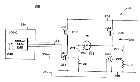
The present invention, schematically illustrated in Figure
2, is a dynamic brake, generally designated 210, for power door
20. In this embodiment, the motor 76 has at least a first
motor terminal 261 and a second motor terminal 262. The motor
76 is energized by a pulse width modulated H-bridge amplifier,
generally designated 220. H-bridge amplifier 220 is connected
to a first power line 201 having a first voltage and a second
power line 202 having a second voltage, the second voltage
differing from the first voltage.
The H-bridge amplifier 220 includes a first switch 221
which connects the first motor terminal 261 to the first power
line 201 and it includes a second switch 222 connecting the
second motor terminal 262 to the first power line 201. It also
has a third switch 223 connecting the first motor terminal 261
to the second power line 202 and a fourth switch 224 connecting
the second motor terminal 262 to the second power line 202.
In the H-bridge amplifier 220, to which the presently
preferred embodiment of the invention is adapted, first switch
221 has a first switch control terminal 231, second switch 222
has a second switch control terminal 232, third switch 223 has
11
CA 02282071 1999-09-10
a third switch control terminal 233 and fourth switch 224 has
a fourth switch control terminal 234. Control inputs 231, 232,
233 and 234 have signal connections (not shown) to a motor
control signal generator (not shown) for causing a torque in
motor 76 in either direction to open or close door 20.
The dynamic brake 210 has a brake control signal
generator, generally designated 240, which preferably is
disposed within a complex programmable logical device,
generally designated 250. Brake control signal generator 240
includes an input signal connection 246 for receiving an input
signal indicative of a need to apply the dynamic brake 210.
Further, the brake control signal generator 240 has at least
one output signal line 241, or 242, having a signal connection
to a control terminal 231 of the first switch 221 and to a
control terminal 232 of the second switch 222. The brake
control signal generator 240 responds to the input signal
indicative of a need to apply the dynamic brake 210 by
supplying at least one control signal to the control input 231
of the first switch 221 and to the control input 232 of the
second switch 222. In this manner, the at least one control
signal causes the first switch 221 to be closed and the second
switch 222 to be closed so that the motor 76 is shorted through
the first switch 221 and the second switch 222, thereby
allowing a braking current through the motor 76 driven by an
emf of the motor 76 and hence dynamically braking the motor 76.
12
CA 02282071 1999-09-10
In the presently preferred embodiment, the brake control
signal applied on the signal line 241 to control input 231 of
switch 221 and the brake control signal applied on signal line
242 to the control input 232 of switch 222 are pulses which are
sequentially disposed in time. It is also preferred that the
pulses be pulse width modulated to control a time averaged
value of braking current through motor 76.
It is presently preferred that dynamic brake 210 also have
at least one first capacitor 271 connected in parallel to the
first switch 221 and at least one second capacitor 272
connected in parallel to the second switch 222 in order to
prevent undesirable voltage spikes due to interruption of the
braking current through motor 76. It is also preferred that at
least one resistor 211 be placed in series with such first
capacitor 271, or at least one resistor 212 be placed in series
with the second capacitor 272, or both, to prevent current
oscillations through first capacitor 271, second capacitor 272
and motor 76 due to interruption of the braking current through
motor 76.
Preferably, a current sensor such as sensor 236, shown in
Figure 2, provides a current indicating signal on current
feedback line 238 to the brake control signal generator 240.
Figure 3 shows an alternative configuration in which a current
feedback signal is obtained on current signal line 251 from
current indicating terminal 253 of switch 221.
13
CA 02282071 1999-09-10
Figure 4 shows another alternative configuration in which
a current feedback signal is obtained on current signal line
252 from current indicating terminal 254 on switch 222. The
current indicating signal from sensor 236, current indicating
terminal 253 or current indicating terminal 254 is used to
determine a time averaged current through motor 76 and adjust
the width of the pulses of the brake control signals to limit
the time averaged current to a predetermined current value. It
is preferred that switch 221 and switch 222 be closed whenever
the time averaged braking current is below the predetermined
current value.
The voltage of first power line 201 may be positive
relative to the voltage of second power line 202. Preferably,
however, it is negative relative to the voltage of such second
power line 202.
It is preferred that switch 221 and switch 222 be voltage
controlled, in which case the brake control signals applied to
control input 231 of switch 221 and control input 232 of switch
222 are voltage signals. Preferably, these voltage signals are
pulses which are sequentially disposed in time.
Preferably, switch 221 and switch 222 are transistors and
the brake control signals from brake signal generator 240 are
transistor control signals. Preferably, also, such switches
221 and 222 are field effect transistors and the signals are
voltage signals. In the preferred embodiment, switches 221 and
222 are metal oxide semiconductor field effect transistors and
14
CA 02282071 1999-09-10
the brake control signals are voltage signals. Preferably, a
current indicating signal is obtained from current indicating
terminal 253 on metal oxide semiconductor field effect
transistor 221, or from current indicating terminal 254 on
metal oxide semiconductor field effect transistor 222.
In the presently preferred embodiment, the control signal
generator 240 sends signals to both the first switch 221 and
second switch 222 to close them when door 20 has been closed to
provide a force opposing opening of door 20.
Figure 5 is a plot of the velocity of door 20 during a
normal opening or closing stroke and the velocity during an
emergency stop provided by the dynamic brake of this invention.
The abscissa 281 indicates time and the ordinate 282 indicates
the door speed. The velocity, generally indicated as 280,
during a normal stroke starts from zero velocity 284 and
accelerates at a constant rate on acceleration ramp 286. Upon
reaching the maximum velocity 288 it remains at that velocity
until it begins decelerating at a constant rate, following
deceleration ramp 289, until it reaches the zero speed 284.
At any time during the stroke, an obstruction detection
system (not shown) may send a signal for eddy current braking
on signal line 246. The door 20 then decelerates rapidly
following the dynamic braking curve, generally designated 290,
which includes linear portion 292. Linear portion 292
corresponds to the predetermined constant time averaged current
CA 02282071 1999-09-10
through motor 76. It should be noted that motor 76 preferably
is a DC motor having a permanent magnetic field.
When motor 76 has almost stopped, its emf is insufficient
to maintain the predetermined current and the velocity profile
then follows terminal portion 294 of dynamic braking curve 290.
The distance that the door 20 travels before stopping is given
by the area 299 under the dynamic braking curve 290.
In another aspect, the present invention provides a method
of braking a power door 20 which is moved by an electric motor
76 driven by an H-bridge amplifier 220. Such H-bridge
amplifier 220 includes four switches 221, 222, 223 and 224
which are connected to the motor 76. The method consists of
communicating control signals to control terminals 231 and 232
of two of the switches 221 and 222 having electrical connection
to each other and to the terminals 261 and 262 of the motor 76
to provide a current return path, generally designated 270, to
allow a braking current through the motor 76 driven by an emf
of the motor 76 and hence dynamically braking such motor 76.
Current return path 270 consists of first switch 221,
second switch 222 and motor 76. In a presently preferred
embodiment of the invention, the method includes the step of
generating the control signals as pulses sequentially disposed
in time. The width of these pulses is, preferably, modulated
to control a time average of the current through motor 76 and
these pulses are modulated to limit the time average of the
current through the motor 76 to a predetermined current value.
16
CA 02282071 1999-09-10
In an alternative embodiment of the invention, a motor
having more than two terminals may be employed. In particular,
a brushless DC motor having three terminals may be employed
using the circuit illustrated in Figure 6. Electric motor 360,
having terminals 361, 362 and 363, is powered by door drive
amplifier 320. Door drive amplifier 320 has a first group of
switches 380 consisting of switches 321, 322 and 323 which
connect the motor terminals 361, 362 and 363 to a first power
line 201 having a first voltage. Amplifier 320, also, has a
second group of switches 390 consisting of switches 324, 325
and 326 which connect motor terminals 361, 362 and 363 to a
second power line 202 having a second voltage.
In the door drive amplifier 320 to which this alternate
embodiment of the invention is adapted, first switch 321
includes first switch control terminal 331, second switch 322
includes second switch control terminal 332, third switch 323
includes third switch control terminal 333, fourth switch 324
includes fourth switch control terminal 334, fifth switch 325
includes fifth switch control terminal 335 and sixth switch 326
includes sixth switch control terminal 336. Control terminals
231, 232, 233, 234, 325 and 326 have signal connections (not
shown) to a motor control signal generator (not shown) for
causing a torque in motor 360 in either direction to open or
close door 20.
17
CA 02282071 1999-09-10
Dynamic brake 310 has a brake control signal generator,
generally designated 340, which preferably is disposed within
a complex programmable logical device, generally designated
350. The brake control signal generator 340 includes an input
signal connection 346 for receiving an input signal that is
indicative of a need to apply the dynamic brake 310. The brake
control signal generator 340 has at least one output signal
line, preferably, output signal lines 341, 342 and 343 having
a signal connection to control terminal 331 of the first switch
321, control terminal 332 of the second switch 322 and control
terminal 333 of the third switch 323.
The brake control signal generator 340 responds to the
input signal on line 346 by supplying at least one control
signal to at least two of the control terminals 331, 332 and
333. Preferably, brake control signals are supplied on lines
341, 342 and 343 to control inputs 331, 332 or 333. Control
signals applied to two or more control terminals 331, 332 and
333 cause two or more of the switches 321, 322 and 323 to
conduct and provide at least one dynamic brake current return
circuit for at least one dynamic braking current driven by an
emf of motor 360 and hence damping motor 360.
In the preferred case, control signals are applied to all
three control terminals 331, 332 and 333 to provide three
braking currents between terminals 361, 362 and 363. To limit
voltage spikes caused by interruption of currents through motor
360, it is presently preferred that a capacitor 371 and
18
CA 02282071 1999-09-10
resistor 311 be placed in parallel with switch 321. Likewise,
it is presently preferred that a capacitor 372 and resistor 312
be placed in parallel with the switch 322 and that capacitor
373 and resistor 313 be placed in parallel with the switch 323.
It is further preferred that the control signals applied to
terminals 331, 332 and/or 333 be pulse width modulated to limit
an average value of the braking current through motor 360.
While a presently preferred and various additional
alternative embodiments of the instant invention have been
described in detail above in accordance the patent statutes, it
should be recognized that various other modifications and
adaptations of the invention may be made by those persons who
are skilled in the relevant art without departing from either
the spirit of the invention or the scope of the appended
claims.
19