Note: Descriptions are shown in the official language in which they were submitted.
CA 02282141 1999-11-26
GRAVI!:L PACK APPARATUS AND METHOD
BACKGROUND OF THE INVENTION
FIELD OF THE INVENTION
The invention relates to a gravel packing apparatus and method for use in a
subterranean well in a "thru-tubing" operation.
DESCRIPTION OF THE P>E~IOR ART
Of considerable magnitude in the production of hydrocarbons, such as oil and
gas,
from a producing well is the problem of sand flow into the wellbore from
unconsolidated
formations. Production of sand with the flow of hydrocarbons will cause the
wellbore to
gradually fill-up with minute sand and silt particles until production
perforations in the casing
and, often times, the end of production tubing inserted therein, are covered,
resulting in a
significant reduction in fluid production. In many instances, sand production
will cause the
well to stop producing.
While such problem is frequently encountered in oil and gas wells, it will be
appreciated that such problems are equally encounterable in water wells.
Accordingly, it is
contemplated that the invention has utility in abating this problem in water
wells as well as oil
and gas wells. Accordingly, by use of the term "subterranean well" herein, I
mean to refer to
and identify water, oil, gas, and other subterranean wells of similar nature.
Accordingly, the
use of the phrase "production :none" will refer to and mean a zone within any
such well in
which a fluid desired to be produced may be encountered, such as water, gas,
oil, and/or
mixtures thereof.
In addition to reduction of fluid production, flow of sand may also cause
severe
damage to equipment, such as pumps, chokes and the like. In flowing wells,
fluid velocity
may be sufficient to scavenge sand within the wellbore and produce it with the
fluid
hydrocarbon, resulting in hole's being cut in the tubing and flow lines, as
well as in valuing
components, such as the Christmas tree' disposed at the top of the well
through which
production tubing and casing are communicated, connected or disposed.
1
CA 02282141 1999-11-26
When, referring to "Christmas tree" herein, I mean to refer to an assembly of
valves
and fittings which are attached to the upper most connection of the tubing
head, used to
control well production and which may be distinguished from a "wellhead" which
includes all
permanent equipment between the upper most portion of the surface casing and
the tubing head
adapter connection. A tubing head adapter adapts the upper most connection of
a tubing head
to the lower most valve of the Christmas tree.
One well known means of controlling flow of sand into the wellbore is the
placement
of gravel around the exterior of a slotted, perforated, or other similarly
formed liner, isolation
means, or screen. When used herein, all such references and constructions are
the equivalent
of the others and can be generally referred to as production or gravel pack
screens. The
selected construction of such components is not particularly significant to
the present invention
but the function of filtering out the sand produced with the oil or gas or
water is common to
all such constructions to thus prevent its entry into the wellbore and thence
to the top of the
well. It is important to size the gravel for proper containment of the sand.
Additionally, the
slotted liner, perforated pipe, ~or screen must be designed to prevent entry
of the gravel or sand
itself into the production tubing.
Most gravel pack assemblies incorporate two vertically spaced apart versions
and
sections of such "screens, " with the lower section being commonly referred to
as the "tell-tale"
screen, and the second or higher screen assembly being referred to as the
gravel pack screen.
Two separate sections of screen bridge the perforated or production zone with
the tell-tale
screen being the first to receive the fluid returns interior of the apparatus
during the gravel
packing operation. As gravel is packed upwardly around the tell-tale screen
and to the top of
the gravel pack screen, an increase in fluid pumping pressure will be detected
at the top of the
well.
As described below, production of produced fluids in the zone will be
conducted
through the upper gravel pack packer, through the interior of the outer
housing of the
assembly remaining in the well after retrieval of the mandrel and cross-over
tool components,
thence through the opening in the lower end of the production conduit
extending into the
producing zone through the bore of a set production packer.
2
CA 02282141 1999-11-26
Although other fluids leave been used, treated and filtered water with a
desired
concentration of chlorides plus a synthetic polymer or other shear thinning or
viscosity
controlling substance, is preferably used in most gravel packing processes
during the packing
and cleaning or flushing procedures. 'the water is treated to remove
contaminants such as
cement particles, scale, and other foreign material generally resulting from
the circulation of
fluid in the wellbore before recirculation into the well with additional
gravel, or during any
cleaning or flushing procedure.
Gravel packing may be effected as a portion of the initial completion
operation or may
be provided during a workover operation. Some present day workover operations
contemplate
the use of "thru-tubing" operations in which the production tubing remains in
the well and the
remedial or workover operation is effected through the production tubing by
use of tubular
conduits such as continuous coiled tubing, or the like. Such "thru-tubing"
tubular conduits
may, of course, include a workover string of tubing made up of a series of
tubing sections
which are threaded or otherwise secured one to another and which are
introduced into the well
with the Christmas tree in place and through a selectively openable passageway
through the
Christmas tree and then concentrically disposed through the production tubing.
The present invention includes incorporation of expandable elastomeric packing
elements which, because the oAeration will be performed "thru-tubing,"
preferably must be of
a construction in which the sealing element of the inflatable packer is
capable of expanding
from the initial outer diameter during t:he running-in condition to the outer
diameter when such
packer is in the fully expanded condition of at least a ratio of two or more.
Such packers are
commercially available and arf~ identified as the Model 373 Inflatable Packer
made available
by High Pressure Integrity, Inc., of New Orleans, Louisiana. The configuration
of such
packers is illustrated in Produca Publication entitled "I-HIP Inflatable
Tools" dated 1993, of
High Pressure Integrity, Inc. , (Vew Orleans, Louisiana.
In U.S. Patent No. 3,9()1,318, there is shown and disclosed a one trip gravel
packing
operation incorporating a fluid flow cross-over assembly which is moved to
various positions
by tubing manipulation. This patent contemplates traditional gravel packing
operations and
does not utilize an inflatable packer element, nor is the cross-over assembly
utilized to provide
3
CA 02282141 1999-11-26
a passageway to set the packer or to thereafter provide a passageway for
introduction of the
gravel and carrier fluid in the well nor to manipulate valvings by application
of pressure
subsequent to the setting of the packer. Moreover, tubing rotation is required
during certain
steps in the packer setting operation, as well as disengagement of the work
string when it is
desired to leave the gravel pack compcments in the well. Thus, where coiled
tubing is to be
the "thru-tubing" component, the '318 tool cannot be used.
Likewise, U.S. Patent No. 4,401,158, discloses the use of a similar device in
concert
with packing elements for mul.ti-zone gravel packing and perforating of a
well.
U.S. Patent No. 4,627,488, discloses an isolation gravel packing system
utilizing
conventional mechanically set packers having slips and a cross-over tool
disposed within the
interior of the device for conventional isolation gravel packing with the
device carried on a
conventional work string into the well.
U.S. Patent No. 4,856,590, utilizes coiled tubing in a thru-tubing operation,
but
utilizes a pre-packed screen apparatus.
U. S. Patent No. 4, 860 , 361, incorporates a coiled tubing string that does
not require
utilization of a cross-over assembly or multiple packers.
U.S. Patent No. 5,219.,025, incorporates a cross-over assembly to facilitate
pumping of
a gravel slurry in a wellbore and is of limited construction with respect to
the configuration of
the cross-over assembly.
U.S. Patent No. 5,069..280, shows a variation of gravel packing incorporating
a gravel
packer which provides sequential locking and sealing of the packer in the well
and includes a
releasing mechanism for mechanically disconnecting it from the packer.
U.S. Patent No. 5,174,379, discloses a single trip gravel packing and
perforating
operation typical of the prior art in such combination.
U.S. Patent No. 5,332,038, discloses a gravel packing system incorporating a
combination packer and setting tool for the packer which is mechanically set.
U.S. Patent No. 5,343,953, discloses a thru-tubing recirculating device
incorporating a
cross-over assembly and a gravel packing screen.
4
CA 02282141 1999-11-26
U.S. Patent No. 5,377,749, teaches the introduction of coiled tubing through a
wellhead and the utilization o~F a mechanically set packer with a flow control
cross-over
assembly for providing a fluid flow path for gravel packing only. The packer
disclosed in this
patent is of extremely restrictf:d expansion and requires mechanical
manipulation of the tubing
string for the setting.
U.S. Patent No. 5,413,176, is directed to a device for repairing a gravel
packing
screen already in place, and incorporares a mechanically set packing device.
U.S. Patent No. 5,609,204, discloses a gravel packing device incorporating a
cross-
over assembly and a mechanically set packer with a washpipe stabbed into a
seal bore bridging
the production screen.
U.S. Patent No. 5,620,050, discloses a method for setting a hydraulic packer
used in a
gravel packing operation on rf;medial coiled tubing disposed through a
wellhead. The packer is
set hydraulically. This patent discloses hydraulic actuation of a conventional
non-elastomeric
expansible packer which incorporates slips for purposes of anchoring the
packer against the
inner wall of the well. Moreover, this patent does not use a flow control
cross-over assembly
with concentrically disposed fllow passageways therethrough that can be used
to both set the
packer and open certain valves to circulate the gravel and carrier fluid.
Promotional literature .entitled "Eclipse Series Packers/Plugs for Coiled
Tubing"
discloses the use of a conventional non-inflatable packer with slips and a
cross-over assembly
in which a passageway in the cross-over assembly is utilized to transmit
pressure to
mechanically move the slips and the conventional packer into set position.
Only one packer is
utilized and the cross-over assembly cannot be used to provide setting of
plural packers
because one of the concentric passageways through the cross-over assembly
permits fluid flow
therethrough in only one direction, i.e., to the top of the well, for returns.
Electric line gravel packing is an alternative to the thru-tubing concept, and
is typified
in U.S. Patent No. 5,033,549. Likewise, U.S. Patent No. 5,115,860 discloses a
similar
method of implementing a thru-tubing gravel packing operation.
Finally, Society of Petroleum Engineers Paper No. 23130 entitled "Thru-Tubing
Sand
Control Techniques Reduce Completion Costs," presented at Offshore Europe
Conference held
CA 02282141 1999-11-26
in Aberdeen, Scotland, 3-6 September, 1991, generally discloses commercially
available
gravel packing components and tools as well as various types of perforated
tubing, screens,
and slotted liners, which may be incorporated into the present invention.
SUMMARY OF THE INVENTION
The present invention provides a gravel packing apparatus and method which is
intended to be utilized on a tubular conduit which is introduced through
another conduit into
the well. The well may be cased, or open hole, and when it is open hole, the
inner wall
within its bore constitutes the area which is sealingly engaged with the
inflatable packer
elements as described herein. The tubular conduit may be coiled tubing, a
workover string
made up of threaded sections, or any other tubular conduit of known or similar
construction.
The apparatus incorporates elastomeric; inflatable element means which provide
a gravel pack
packer and, if a second such packer is utilized, provides a sump packer
therebelow. It is not
necessary for two packers to be run on the same conduit in the apparatus, and
if desired, the
sump packer may be of the inflatable variety and previously set in the well or
may be a bridge
plug, retrievable packer or sump packer run in and set by wire line, electric
line, work string,
or the like, and may be mechanically or hydraulically set or otherwise
actuated in known
manner. The sump packer may be provided with an open bore which may be used to
transmit
produced fines in low velocity production fluids through the bore and into a
rat hole, which
serves to collect and contain the fines away from interference with or
bridging of the
production flow and inside the gravel pack screen and/or in any position of
the production
fluid passageway through the assembly and the tubular conduit or production
tubing.
When the preferred inflatable packer elements are utilized in the present
invention, they
are required to provide expansion to the fully expanded condition for sealing
against the well
wall or casing to at least twice the diameter of the element as it is in its
running or run-in
condition. This is highly desirable in thru-tubing operations described herein
to permit the
packer to travel freely through the Christmas tree and the production tubing
on the tubular
conduit, such as coiled tubing, and then be able to expand sufficiently
outwardly to the given
wall of the well which could have an inner diameter considerably greater than
that of the
6
CA 02282141 1999-11-26
production tubing inner diameter. Through experimentation and testing, I have
discovered that
this expansion ratio of at least two-to-one is sufficient to assure
operational integrity in what is
referred to as "thru-tubing" operations.
The present invention .also contemplates use of a fluid flow cross-over
assembly in
which concentric pathways therethrough may be utilized to inflate the
inflatable packer
element means as well as to pn~ovide pressure to valuing means on a control
mandrel to
communicate the interior of the washpipe with the well annulus through the
tell-tale screen to
permit circulation of the clean fluid subsequent to deposition of gravel
carried in the fluid
exterior of the screen as well as to open a valve in the housing above the
gravel pack screen to
permit gravel in the carrier fluid to be deposited exterior of the screens.
When a gravel pack packer and a sump packer are carried on the tubular
conduit, the
flow control cross-over assembly permits one of the concentric tubular
passageways
therethrough to transmit inflation fluid pressure to one of the packers while
the other of the
concentric passageways within the cro:~s-over assembly will transmit inflation
fluid pressure to
the other of the packer assemblies. Valuing means are provided for the packers
such that the
lower of the packers is set prior to the upper of the packers and the valve
within the screen
assembly is not opened until each of the packers are completely set.
The pressure through the cross-over assembly during the packer setting
operation will
also open the fluid passageway between the mandrel and the housing of the
apparatus to permit
the gravel packing carrier fluid with the gravel to pass through the cross-
over assembly and
into the well after shifting of t:he apparatus by the coil tubing to
telescopically expand the
mandrel relative to the outer housing to move the apparatus to the gravel
packing position.
Additional and subsequent manipulation of the tubing will further
telescopically expand the
mandrel relative to the housing; to permit alignment of ports for cleaning of
the well annulus
and the interior of the tubing subsequent to the gravel packing operation by
normal circulation
or reverse circulation.
The invention also contemplate: use of the apparatus without a washpipe to
provide a
one trip gravel packing squeeze operation. Moreover, the apparatus may be
easily converted
CA 02282141 1999-11-26
to remove the flow control cross-over assembly to provide an alternate
apparatus and method
of one trip gravel packing of t:he well.
BRIEF DESCRIPTION OF THE DRAWINGS
Fig. 1 is a longitudinal. schematic, partial sectional view of the apparatus
of the present
invention and its related components after setting of the elastomeric
inflatable elements to
expanded condition and subsequent to the gravel packing operation.
Fig. 2 is a view similar to that of Fig. 1, schematically showing the
preferred apparatus
of the present invention subsequent to retrieval of the control mandrel, flow
control cross-over
assembly and washpipe components out of the well with produced fluids being
produced
through the production tubing to the top of the well, as shown.
Figs.3A-3X constitute, together, a longitudinal cross-sectional view of a
preferred
embodiment of the present invention shown in run-in position. The arrows
indicate the flow
path of the inflation and valve actuating fluids through each of the
concentric flow paths
defined through the flow control cross-over assembly during setting of the
packers and the
opening of gravel packing valve on the housing and the return flow valve
within the screen
assembly.
Figs. 4A-4X are views similar to those of Figs. 3A-3X, showing the inter-
relationship
of the various component parts of the apparatus of the present invention
subsequent to the
setting of the expandable packing elements and the opening of the valve
components.
Figs. SA-5S show the apparatus shifted to a first telescopically expanded
position for
gravel packing. The arrows show the :flow path of gravel in a carrier fluid
being carried
through the cross-over assembly for deposition below the gravel pack packer
exterior of the
screen with returns through another of the concentric flow passageways through
the flow
control cross-over assembly and then outwardly of the device to the top of the
well.
Figs. 6A-6T are views similar to those of Figs. 3A-3X, 4A-4X, showing the
apparatus
of the present invention telescopically shifted to a third position to permit
reverse circulation
and cleaning of the well above the gravel pack packer subsequent to the gravel
packing
operation.
8
CA 02282141 1999-11-26
Figs. 7A-7Q illustrate the position of the relative components when the
control
mandrel, the cross-over tool and the washpipe are retrieved from the top of
the well for
leaving the balance of the components in the well for production purposes and
detail the view
of Fig. 2.
Figs. 8A-8N are views similar to the Figs. 4-6 sets, illustrating a
modification to the
present apparatus for one trip circulating without the utilization of the
washpipe.
Figs. 9A-9N constitute similar views of another configuration of the present
invention,
illustrating the components incorporated to provide a dedicated circulating
squeeze tool, with
the mandrel changed relative to the cross-over tool and the absence of the
utilization of the
washpipe.
DESCRIPTION OF THE PREFERRED EMBODIMENTS
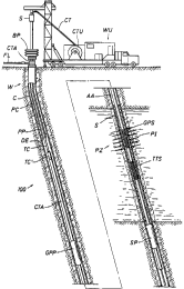
Now with reference to Fig. 1, there is shown in vertically disposed partial
sectional
schematic illustration, the prei=erred apparatus 100 of the present invention.
A workover unit
WU is operationally positioned immediate the well W with the unit WU
containing a coiled
tubing unit CTU including a lf:ngth of continuous coiled tubing CT, which is
the preferred
tubular conduit.
The workover unit WL1 includes a swivel joint assembly S through which the
coil
tubing CT is inserted. The workover unit WU also includes a blowout preventer
stack BP
which is engaged above a Christmas tree assembly CTA prior to introduction of
the coiled
tubing CT and includes a controlled passageway therethrough through which the
coil tubing
CT is disposed through the Christmas tree assembly CTA. The Christmas tree
assembly CTA
also receives a flow line FL for transmission of the production fluids.
As shown, the well W includes an inner wall which, as illustrated in the
preferred
embodiments, is cased with casing C, <,~uch that the casing C defines the
inner wall of the well
W. A production conduit PC with its distal end DE is disposed through the
casing C and
defines within it a fluid passageway FP communicating through the Christmas
tree assembly
CTA and the flowline FL. The open distal end DE of the production tubing PT
extends
through a production packer PP which isolates the annular area of the well W
at such point
9
CA 02282141 1999-11-26
between the exterior of the production conduit PC and the inner wall of the
well W defined by
the casing C. As shown in Fig. 1, the tubular conduit TC, i.e., the coiled
tubing, extends into
the well W and out of the distal end DE of the production conduit PC, and
carries thereon a
tubular connector TC' .
The apparatus 100 is shown in Fig. 1 on the tubular conduit TC and disposed
within a
production zone PZ having an annular area AA. The apparatus 100 contains a
first
expandable elastomeric inflatable element means, or gravel pack packer GPP,
below a flow
control cross-over tool assembly CTA which has concentric flow passageways for
transmitting
hydraulic fluid pressure for the setting of the gravel pack packer GPP and a
sump packer SP(if
used), and also provides fluid passageways for introduction of gravel in a
carrier fluid for the
gravel packing of the well.
Fig. 1 also schematically illustrates portions of the apparatus 100 in
schematic format
as shown with the particle isolation means being illustrated as a screen of
conventional
construction having members defined as a gravel pack screen GPS and a tell-
tale screen TTS
therebelow. As shown, sized particulate matter, or gravel pack sand S, is
shown disposed
within the annular area AA to block larger particulate matter within the
production zone PZ
from being carried with the produced fluids through a perforated interval PI
through the casing
C into the annular area AA, and thencE; interior of the tubing PC to the top
of the well.
Now referring to Fig. 2, the preferred apparatus 100 is schematically shown as
it is left
within the well W subsequent to the gravel packing operation as described
herein. The
workover assembly and blow out preventer stack have been removed, leaving only
the
Christmas tree and the production tubing PT to the flow line FL in place at
the top surface of
the earth.
Now referring to Figs. 3A-3X, the coil tubing CT is secured to the apparatus
100 by a
coil tubing connector CT' of conventional construction. The apparatus 100 is
shown having
an outer cylindrical housing 101 having interengaged component members 101-C
through 101-
CC. Housing component lOlC has a plurality of bores 102 for receipt of a
series of shear
screws 103 disposed therethrough and respectively extending into a series of
thin grooves 170
defined on a control mandrel 104 extended therein. Disposed 180 °
offset therefrom is a shear
to
CA 02282141 1999-11-26
pin 103A which initially, but selectively secures the outer housing 101 and
the mandrel 104 in
run-in position. The control mandrel 104 is secured by threads 105 to a top
sub 106 which, in
turn, is secured to a member 101-A and to the coiled tubing connector CT' at
threads 107.
The control mandrel 104 also receives a series of collapsed retainer rings 108
disposed
therein which are shown in Fig. 3A in compressed and collapsed position but,
as described
below, are selectively expand;~ble to rcaain the control mandrel 104 in a
second or extended
position relative to the outer cylindrical housing 101 when the housing 101
and mandrel 104
are telescopically extended to a first position (Figs. 4A-4X) in response to
pick up of the
coiled tubing CT, for purposes described below.
The outer cylindrical housing member 101-C also includes a series of
circumferentially
extending reverse circulation ports l0a (Fig. 3C) which, when aligned with
ports 110 in the
flow control cross-over assembly CX c:arried on the control mandrel 104
provide a reverse
circulation passageway through the apparatus 100 for cleaning of the interior
of the apparatus
100 and the coiled tubing CT, as well as the annular area of the well above
the set gravel pack
packer GPP. The outer cylindrical housing 101 further includes a second series
of
circumferentially extending fluid ports 111 which, when aligned with the ports
110 on the flow
control cross-over assembly CX provide for returns of clean fluid to the top
of the well W. As
shown in the run in position in Figs. 3 A-3X, a circumferentially extending
elastomeric O-ring
seal element 110A is disposed on the control mandrel 104 and seals against the
inner wall of
the outer cylindrical housing 101 to pr.°vent fluid communication
therebetween at that point.
The control mandrel 102 also includes an O-ring seal housing portion 112 for
receipt of an O-
ring 112A therein which, in the position shown, does not seal relative to the
outer cylindrical
housing 101 because of a fluid flow pathway 113 profiled laterally in relation
to the flow
control cross-over assembly CX thrau~;h the outer housing 101 there across.
However, when
the apparatus 100 is moved to the position as shown in Figs. 4A-4X, and the
position shown in
Figs 5A-5X, the seal 112A will act in concert with the seal 110A to provide
the top opening to
a passageway 115 through the cross-over assembly CX for return of fluids to
the surface.
The cross-over assembly CX is defined as a tubular member of the control
mandrel 102
having concentric passageways 114 anti 115 defined therein as provided by
outer tubular
11
CA 02282141 1999-11-26
member 114A and inner tubular wall member 115A. The cross-over assembly CX as
described extends longitudinally downwardly within the apparatus 100 on the
control mandrel
104 and within the outer housing 101 Through a first valuing means 116 for
transmitting
inflation fluid pressure within the coiled tubing CT through the passageway
114 for setting of
the inflatable packer identified as a gravel pack packer GPP, and continues
downwardly within
the outer housing 101 across the gravel port 157 and associated valuing
assembly. While the
outer concentric passageway 114 is blocked by a diverter 190, the inner
concentric passageway
115 continues downwardly through a passage 138 in a sleeve 137 (Fig. 3P) of
the piston rod
assembly 133 interior of the tell-tale screen TTS, thence to the second
valuing means 149 (Fig.
3R) for actuation of the lower or sump packer SP.
Now referring to Figs. 3E and 3F, the first valuing means 116 includes a
poppet
assembly 117 having at one end thereof a defined integral elastomeric seal
member 118 which,
when the poppet is in the closed position during running in of the apparatus
100 and before
activation thereof to set the gravel pack packer GPP, seals against a
companion bore wall 119
on an outer housing member 120. The poppet 117 also has a series of
elastomeric O-ring seal
elements 121 which seal against the inner wall of a control mandrel sleeve
member 122 having
multiple flow ports 123 circumferentially disposed therein communicating with
the flow
passageway 114 in the housing; 114A through the flow control cross-over
assembly CX. The
upper end of a poppet spring assemblage 124 is in contact with the lowermost
end of the
poppet 117 for urging the seal member 118 into sealed relationship relative to
seal bore 119,
with the lowermost end of the poppet spring 124 being biased against a sliding
pedestal
member 125 having a series of fluted slits 125A therein.
The pedestal member 125 is secured by shear screws 129 to a companion outer
housing
sleeve member 127 carried within the housing member 101-G which, in turn, is
secured by
threads 128 to the outer housing member 101-H. The shear screws 129 are
disposed between
the members 125 and 127 to regain the valuing means 116 in closed position, as
shown. The
passageway 130 defined between the lriembers 122 in the valuing means 116 and
the outer
component parts of the housing 101 thereacross provide a passageway for
transmission of fluid
pressure to a control mandrel CM in th.e inflatable gravel pack packer GPP to
move same from
12
CA 02282141 1999-11-26
the initial position as shown in Figs. 3A-3X to the expanded condition shown
in Figs. 4A-4X.
The inflatable gravel pack packer GPP has an outer wall OW (Fig. 3A) having an
outer
diameter D-1 when it is in the initial retracted and run-in condition, as
shown in Figs. 3A-3X,
and when in the expanded condition as. shown in Figs. 4A-4X and 5A-5S, will
have an outer
diameter D-2 (Fig. 4G) at least twice that of the outer diameter D-1.
The gravel pack packer GPP has a series of exposed rib elements R (Fig. 3G)
thereon
which assist in setting or anchoring thf~ gravel pack packer GPP and
maintaining it in set
position as shown in Figs. 4A-4X. The gravel pack packer GPP continues below
the exposed
ribs with an inflatable element 131 thereon (Figs. 3H and 4G).
As described previously in the SUMMARY OF THE INVENTION, it is not necessary
that the apparatus 100 include a sump packer SP thereon, but if such sump
packer SP is so
provided, it is defined by a second inflatable elastomeric packer and is set
prior to the gravel
pack packer GPP by inflation fluid pressure which is carried through the
apparatus 100 within
the cross-over assembly CX and in communication with the inner concentric
tubing flowpath
115 through the first valuing means 116 and interior of the gravel pack packer
GPP.
In the event that a sump packer SP is not utilized or incorporated into the
apparatus 100
as shown, the passageway 115 may be blocked by provision of a ball 180 which
may seal
against a companion seat 180A on a ball sleeve housing 181 on the control
mandrel 104 or by
use of similar means at some point within the passageway 115. (See Fig. 3K). A
bar 182
bridges across the interior of member :181 to provide a cage against upward
travel of the ball
180.
The passageway 115 for the setting of the sump packer SP is defined below the
inflatable element 130 within a washpipe 131 which is an extension of tubing
defining the
passageway 115 within the inflatable element 130 and is secured to the tubing
115A defining
the cross-over passageway 11_'~ within i:he cross-over assembly CX. The
washpipe 131 is
secured at threads 132 to the top of a piston rod assembly 133, which, in
turn, includes a
cylindrical housing 134 with fJ.ow port;> 135 disposed therethrough for
receipt of the gravel
carrier fluid during return of such fluid subsequent to depositing of the
gravel exterior of the
tell-tale screen TTS, and gravel pack screen GPS as described hereafter. A
series of shearable
13
CA 02282141 1999-11-26
screw members 136 are received within the housing 134 and extend to
selectively engage a
piston sleeve member 139 disposed within the housing 134. The piston sleeve
member 139
has a series of seal elements 138A and 138B which straddle the ports 135 when
the shear
screws 136 are engaged to maintain the sleeve 137 in closed or run-in
position.
It will be appreciated that the shear value of the pins or screws 136 will be
higher than
those in the valuing means 14!~ and the: valuing means 116 associated with the
gravel pack
packer GPP, to assure that same permit pressure transmission to completely set
the packers
before the ports 135 or the ports 157 are opened.
The piston sleeve 137 also has defined therethrough a plurality of
longitudinally
extending fluid passageways 138 which are in communication with the passageway
115
through the cross-over tool CX for continued transmission of fluid pressure
within the piston
rod assembly 133 through the housing 134.
The sleeve 137 also receives the lowermost end 140 of a solid wire or rod
component
141 which prevents a floating check ball 142 carried within the washpipe 131
from sealing
against a ball seat 143 defined at the upper most end of the piston rod
housing 134 during the
packer setting operation.
The piston rod assembly 133 also includes a piston rod mandrel 144 carrying
thereon a
seal piston member 145 with lock nuts 145A and 145B disposed on each side
thereof. During
inflation of the sump packer S:P, the differential pressure caused by such
inflation pressure will
create a tensile load on the piston rod assembly 133 and the seal piston
member 145 to create a
tensile load which, in turn, is transmitted to the shear screws 136 causing
shearing of the
screws 136 so that relative longitudinal movement occurs between the piston
rod housing 134
and the piston rod mandrel 144 such that the ports 135 are opened and the rod
141 is
completely moved within the housing 134 to permit the ball 142 to selectively
seal against the
companion seat 143, as shown in Fig. 5M. The check ball 142 is caged against
upward
movement by provision of the isolation bar 182.
The passageway 138 within the sleeve 136 which communicates with the
concentric
passageway 115 in the flow control cross-over assembly within the sleeve 136
continues within
the housing 134 of the piston rod assembly 133 and passes exteriorly of the
housing 134 by
14
CA 02282141 1999-11-26
means of provision of ports 146 into a passageway 146A defined between the
exterior of the
housing 134 and the interior of a second or lower valuing means 149 inner
housing member
101-which, in turn, has a series of companion ports 148 for transmission of
pressure and fluid
to the second or lower valvin~; means 149, of like construction as the first
valuing means 116.
In order for proper actuation of the apparatus 100 to occur when a lower or
sump
packer SP is provided, it is necessary ro set such packer SP prior to the
setting of the gravel
pack packer GPP. Therefore, it will be appreciated that the tensile load
through the shear
screws 150 (Fig. 3R) provided in the second or lower valuing means 149 will be
less than that
provided by the shear screws 129 in the first valuing means 116 as well as
that provided in the
shear screws 136 in the piston rod assembly 133, such that a first increase in
tubing pressure
through the coiled tubing CT will be transmitted to the shear screws 150 and
such screws 150
will shear, causing actuation and opening of the poppet assembly through the
valuing means
149.
After the lower or sump packer SP is set, pressure will continue to be
increased within
the coiled tubing CT and the apparatus 100 such that the shear screws 129 in
the first valuing
means 116 are the next to be sheared, causing actuation and opening of the
poppet 117 therein
and the setting of the gravel pack packer GPP. After the setting of the gravel
pack packer
GPP, continued increase in fluid pressure within the apparatus 100 will cause
shearing of the
shear screws 136 to open the return ports 135. Further increase in pressure
will cause
shearing of the pins 161 holding the sl<;eve 160 closed across the gravel pack
ports 157, thus
opening them to the flow passageway 1.14 in the concentric cross-over tool CX.
The washpipe 131 extends lowerly through the interior of the sump pack SP and
extends out of the lowermost outer end 151 of the outer housing 141 of the
apparatus 100. A
normally compressed and biased spring element 152 is carried around the
lowermost end 153
of the piston rod mandrel 144 and within the housing member 131. When pressure
is applied
to the shear screws 136 after the setting; of the sump packer SP and the
gravel pack packer
GPP, and upon severance of the screws 136, the compressed bias defined through
the spring
152 assures sufficient travel of the piston rod mandrel 144 to prevent
obstruction of fluid flow
CA 02282141 1999-11-26
through the ports 135 to permit the apparatus 100 to move to the complete
circulating position,
as shown in Figs. 5A-5X.
The flow control cross-over assembly CX also provides a series of gravel
packing ports
154 (Fig. 3J) which are closed relative to the outer housing 101 by means of
straddling O-ring
seal elements 155 and 156 extending across a companion gravel packing port 157
disposed
through the outer housing 101 which, in turn, prior to manipulation of the
coiled tubing CT
from the run-in and packer setaing position shown in Figs. 3A-3X is bridged by
companion O-
ring seal elements 158 and 15!~ carried at each end of a sliding seal
assemblage 160 held in
port straddling position by means of a series of shear pins 161. The sliding
sleeve 160 is
biased against the shear screws 161 by means of the compression defined
through a spring
member 162 housed between the interior of the sliding sleeve 160 and the
exterior of the
housing member 101 there across.
Now referring to Figs. 3J and 3K, the cross-over assembly CX has defined
thereon
lowerly of the ports 154 an elongated cylindrical diverter sleeve 190 having a
flow passageway
190A therethrough to permit communication of the return fluids from the
circulation pack
upwardly to the top of the well W through the cross-over assembly passageway
115 with
which it is always in communication. 'The sleeve has a series of elastomeric O-
ring seal
elements 191, 192 and 193 carried circumferentially and exteriorly therearound
such that when
the apparatus 100 of the present invention is shifted to the reverse
circulation position shown
in Figs. 6A-6T to circulate and clean out the interior of the coiled tubing
CT, the coiled tubing
CT is picked up, shifting the diverter sleeve 190 upwardly relative to the
outer housing 101 to
bridge the O-ring seal elements 191 and 192 across the flow port 157 to
thereby isolate the
ports 154 so that trapped sand is not bled off into the cross-over tool CT
above the gravel pack
packer GPP. Accordingly, prcasure within the apparatus 100 when in this
position will be
balanced.
The apparatus 100 also features the incorporation of an isolation sleeve
mechanism 200
(Fig. 5J) which is carried on the cross-.over assembly CX for permanently
sealingly bridging
across the gravel pack flow port 157 when the control mandrel cross-over
assembly CX of the
apparatus 100 is retrieved to the top of the well on the coiled tubing
subsequent to the gravel
16
CA 02282141 1999-11-26
packing operation. The sleeve assembly 200 includes an outer elongated
cylindrical housing
201 having first and second O-ring seal members 202 and 203 circumferentially
disposed at
upper and lower ends thereof. A circumferentially extending outwardly beveled
shoulder 204
extends around the lower most end of the sleeve 201 below the lower O-ring
element 203 for
no-go engagement with a companion profiled shoulder 205 on the outer housing
member 101-
N. A normally expanded but selectively collapsible retaining ring element
member 206 is
housed within a companion bore 205A on the outer housing member 101-N. A shear
pin 207
is disposed within the sleeve housing 201 to secure the sleeve housing 201,
selectively, to the
washpipe member 131. Accordingly, when it is desired to retrieve the cross-
over tool
assembly and the washpipe out of the well W on the coiled tubing CT, the
coiled tubing CT is
picked up to shear the screws 103 carried in the grooves 170. When shoulders
204 and 205
interengage, upon additional upward movement of the coiled tubing CT, relative
longitudinal
movement between the sleeve 201 and the washpipe 131 will ultimately result in
such force
being transmitted to the shear pin 206 until it shears, thus permitting
continued upward travel
of the cross-over tool CX and washpipe 131. The interengagement of the
shoulders 204 and
205 will retain the isolation sleeve 201 such that it bridgingly and sealingly
stabilizes across
the port 157 with O-ring seal t:lements 202 and 203 preventing fluid
communication
thereacross. The lower end oil the sleeve 201 passing upwardly, slightly, will
enable the
expandable retaining ring 206 to collapse slightly inwardly to shouldered
engagement around
the lower circumferential end 201A of the sleeve member 201. In such position,
the isolation
sleeve assembly 200 may not move upwardly or downwardly within the assembly,
assuring
permanent closure of the ports 157.
Prior to the apparatus 1.00 being is placed in the position as shown in Figs.
4A-4X, and
subsequent to the setting of thc~ packer~~ and the opening of the return ports
135, pressure may
be applied through the coiled tubing C'r and the apparatus 100 to communicate
the ports 154
and 157 to thereafter permit sand and the carrier fluid to be transmitted
through the outer
passageway 114 of the concenrric passageway through the cross-over tool CX,
whereby the
increase in fluid pressure will be applied against the shear screws 161 and
the bias defined in
the spring 162 will be applied against the sleeve 160 to shift the sleeve 160
downwardly,
17
CA 02282141 1999-11-26
moving the O-ring seal element 156 to the unsealed position to align the ports
157 and 154.
Now, the coiled tubing CT, the passageway 114 and the annular area of the well
W below the
gravel pack packer GPP will be in fluid communication, such that the carrier
fluid with the
sand may continue downwardly for deposit around the tell-tale screen TTS and
the gravel pack
screen GPS thereabove, with the gravel being deposited in such annual area
exterior of the
respective screens TTS and GPS, with fluid returns without such gravel being
carried
interiorly through the port 13.'i .
It will now be appreciated that a feature of the present invention is the
utilization of a
cross-over flow control assembly CX having concentric passageways 114 and 115
which are
utilized not only to set the respective packers (or, in the event that a sump
pack SP is not
utilized, the passageway 115 being blocked, as described earlier) as well as
to provide a fluid
pressure flow passageway to manipulate a valuing mechanism to permit
communication of the
carrier fluid containing the gravel to be transmitted through the apparatus
100 to the annular
area exterior of the apparatus 100 below the gravel pack packer GPP and the
inner wall of the
well W therebelow. Additionally, such passageway 114 through the cross-over
assembly CX
is also utilized during the setting of such packer mechanisms to also open
closed ports through
the apparatus to permit circulation returns to the top of the well through the
coiled tubing.
The termination of the inflation cycle for the sump packer SP occurs when the
sliding
piston 139 is manipulated to open the ports 135. When the piston sleeve 137
slides down and
ports 135 open, the ball 142 falls down onto the seat 143. An increase in
pressure in the
coiled tubing CT is applied to first shear the screws 129 in the valve
assembly 116 to set the
gravel pack packer GPP, as described earlier. Thereafter, pressure is further
increased to
overcome the shear strength of the screws 161 which will allow the sleeve 160
to slide down
and open the gravel pack ports 157. Upon this occurrence, the inflation cycle
of the gravel
pack packer GPP has been completed. The opening of the ports 157 will lower
the pressure in
the passageway 114 and the coiled tubing CT. When the pressure in the coiled
tubing CT so
decreases, then the fluid within the interior of the inflatable packer GPP
pushes and slams the
sleeve 117 closed and the inflation pressure is thus sealed within the packer
GPP, because the
18
CA 02282141 1999-11-26
fluid pressure inside the inflatable packer GPP is higher than the pressure in
the coiled tubing
CT and within the flow passal;eway 11.4.
Now referring to Figs. 4A-4X, the apparatus 100 is shown in position after
inflation of
the gravel pack packer GPP and the sump packer SP and the opening of the
gravel pack valves
and return ports, to create the circulation path downwardly through the
apparatus, with
upward returns, as indicated by the arrows.
Moving to Figs. SA-5 >, the coiled tubing CT is picked up at the top of the
well to
shear the screws 103A disposf~d between the control mandrel 104 and the outer
cylindrical
housing 101. Offset 180° from the screws 103A, the control mandrel 104
has a series of thin
grooves 170 disposed therein for limiting movement of the control mandrel 104
relative to the
outer housing 101 as the apparatus is manipulated from the position shown in
Figs. 3A-3X to
the position shown in Figs. 4A-4X. A shear pin 103 is disposed within the
outer housing 101
and protrudes into the grooves 170 so 'that the pin 103 travels relative
thereto until the coiled
tubing CT is picked up to shear the pin 103 to release the control mandrel 104
from the
housing 101 for retrieval of the cross-over assembly CX and the mandrel 104
from the well W
after completion of the gravel packing operation.
THF; GRAVEL PACHING OPERATION
After the valve and port opening operation with the setting of the packers,
the
apparatus 100 is now ready fo r initiation of the gravel packing operation.
Accordingly, the
coiled tubing CT is picked up at the top of the well to shear the screw 103A
to effect relative
telescopically expanding first movement of the control mandrel 104 relative to
the outer
cylindrical housing 101. The collapsed retaining rings 108 move upwardly and
out of the top
end of the outer cylindrical housing 101, and expansion of the rings is no
longer resisted. The
coil tubing CT is slacked off until the radially expanded rings 108 rest upon
the upper most
end lOlA (Fig. SB) of the outer cylindrical housing member 101-A. Now, the
mandrel 104
and the cross-over assembly CX have been re-oriented relative to the outer
housing 101 to
align the ports 110 and the passageway 115. The gravel packing fluid and
gravel now may be
transmitted through the coil tulbing CT to the exterior of the apparatus 100,
as shown, and
19
CA 02282141 1999-11-26
returns to the top of the well. The fluid travels downwardly within the
apparatus 100 through
the passageway 114 in the cross-over assembly CX with returns through the
concentric
passageway 115 in the cross-over assembly CX and the port 110 in the outer
housing 101.
It will be appreciated by those ~~killed in the art that during the gravel
packing
operation, as described above., a phenomenon or condition called a "sandout"
will be
experienced which occurs whf;n the top of the gravel column in the well
annulus is slightly
over or above the gravel pack screen CAPS. In order for the pumped fluid in
the coiled tubing
CT to go into the either the perforations or down through the gravel pack into
the tail tell
screen TTS and back to the to;p of the well, a substantial pressure drop will
be experienced
which is translated into an increase in pressure at the top of the well within
the coiled tubing
CT. This occurrence confirms that the' gravel packing of the well annulus
below the gravel
pack packer GPP is above the gravel pack packer screen GPS, and pumping is
terminated.
Furthermore, it will also be appreciated that once pumping is terminated, the
resulting static
condition or lack of fluid flow should be permitted for a very short time
interval, i.e., a matter
of 15-30 seconds, or the like. The gravel packing fluid must be agitated by
reactivating
pumping in order to keep the ~cand moving within the fluid in order to avoid
bridging.
Accordingly, the coiled tubing; CT is picked up at the top of the well to
initiate reverse
circulation.
REVI~:RSE CIRCULATION
Once the gravel packing operation has been completed, as described above, it
will be
appreciated that extra gravel will be contained within the fluid in the coiled
tubing CT and the
apparatus 100. Unless the gravel is removed from the interior of the coiled
tubing CT, the
coiled tubing CT may become bridged with such compacted particulate matter.
Now referring to Figs. 6A-6T, when it is desired to reverse circulate to clean
the
interior of coiled tubing CT, the coiled tubing CT is picked up to
telescopically move the
control mandrel 104 expandinl;ly relative to the outer cylindrical housing 101
to a second
telescopically expanded position to align the ports 110 and 109. In such
position, fluid flow
will be prevented within the passageways 114 and 115 within the flow control
cross-over
CA 02282141 1999-11-26
assembly CX by the positioning of the O-ring seal element 112A in sealing
disposition on the
smooth interior bore provided therefore within the outer cylindrical housing
101. Thereafter,
a cleaning fluid may be pumped through the production tubing PT, out the
distal end DE
thereof, and circulated in the annular area above the gravel pack packer GPP
between the
outer cylindrical housing 101 and the inner wall of the well W defined by the
casing C for
circulation through the aligned ports 111 and 109, thence interiorly through
the apparatus 100
through the interior of the control mandrel 104, the coiled tubing CT to the
top surface of the
well W, in order to reverse out excess sand and other particulate debris
resulting from the
gravel packing operation described above.
It will be appreciated tlhat subsequent to reverse circulation cleanout of the
coiled
tubing CT, pumping may be abated and the coiled tubing CT may be slacked off
and pumping
reinitiated to clean out any sand below the reversing ports 110. By so
slacking off on the
coiled tubing CT and moving the apparatus 100 to the circulating position and
then
commencing pumping down the coiled tubing CT, any sand that is located in the
cross-over
assembly CX below the ports 110 will go out of the ports 110. The coiled
tubing CT can
again be picked up to move the apparatus 100 to the reverse circulation
position to continue
reversing out of the hole for iiirther cleaning.
RETRIEVAL OF THE COILED TUBING AND THE CONTROL MANDREL
SUBSEQUENT TO THE GRAVEL PACHING OPERATION
Figs. 7A-7Q constitute a continuous schematic cross-sectional elevational view
of the
apparatus 100 of the present invention subsequent to the completion of the
gravel packing
operation and withdrawal of the tubular conduit, the coiled tubing CT, out of
the well W
through the production tubing PT and the passageway within the Christmas tree
assembly
CTA. After the reverse circulation procedure, as shown in Figs. 6A-6T or, in
the event that
reverse circulation is not necessary, after the gravel packing operation
positioning of the
apparatus 100 as shown in Figs. SA-SS, the coiled tubing CT is picked up such
that the shear
pins 103 disposed between the outer cylindrical housing 101 and the control
mandrel 104 are
sheared. This enables the control mandrel 101, the flow control cross-over
assembly CX
21
CA 02282141 1999-11-26
attached thereto and the washpipe to be retrieved out of the well. The
isolation sleeve 200 is
activated, as previously descriibed, to bridge and close the gravel packing
port 157 in the outer
housing 101. The piston rod ,assembly 133 which is secured to the washpipe is
moved out of
the assembly or outer housing 101 with the control mandrel 104.
The portions of the apparatus 100 now remaining in the well are as shown in
Figs. 7A-
7Q and production fluids may be produced through the screen members to the
interior of the
outer cylindrical housing 101, thence out the upper most end of the outer
cylindrical housing
101 and through the production tubing PT at its distal end DE thereof through
the Christmas
tree CT and into the flow line FL. This operation is illustrated schematically
in Fig. 2.
It will be appreciated tihat when the apparatus 100 is retrieved from the well
with the
remaining portions as shown in Figs. 7A-7Q, a rat hole RH is provided so that
when fines FS
are produced, they will pass into the gravel pack screen GPS and go downwardly
due to lack
of sufficient lift velocity for th.e production fluids and continue to down
and out into rat hole
RH without accumulation and sanding up of the gravel pack in the annular area
around the
gravel pack screen GPS and tail tell screen TTS. The sump packer SP has a
through bore tail
pipe TP at its lower end which communicates to the rat hole RH within the well
W, as shown.
ONE TRIP GRAVEL PACK CIRCULATING SYSTEM
WITHOUT NECESSITY OF WASHPIPE
A feature of the present invention is the ability of the apparatus 100 to be
easily
converted and run such that gravel pack circulating may be done without
necessity of a
washpipe. The configuration of the apparatus 100 for such operation is shown
as in Figs. 8A-
8N and the apparatus 100 is made up at the surface of the well and pinned in
the run-in
position and run into the well such that the outer housing 100 and the control
mandrel 104 are
shifted to a telescopically expanded po;~ition whereby the expansion retainer
rings lOlA are in
expanded relationship to prevent telescopic contraction between the members
101 and 104.
The apparatus of this configuration does include the incorporation of the flow
control cross-
over assembly CX and, when i.n the run-in position, the telescopic shifting of
the cylindrical
housing 101 relative to the control mandrel 104 positions the flow control
cross-over assembly
22
CA 02282141 1999-11-26
CX such that the inner concentric fluid flow passageway 115 is in direct
communication with
the port 111 in the outer cylindrical housing 101. The check ball 181 is
placed into the
apparatus to provide a terminated end to the flow passageway 115.
Since it is not necessary to utilize a washpipe with this configuration, the
washpipe is
replaced by a solid steel bridge plug assembly or platform 600 which is
secured at the
lowermost end of the cross-over assembly CX and threadly secured to the
lowermost end of
the diverter sleeve 190. The assembly 100 is lowered into the well on the
coiled tubing 100,
as described above.
When such conversion is made to the apparatus 100, it will be appreciated that
only
one packer may be utilized, and it will be the inflatable gravel pack packer
GPP. A bridge
plug or platform will have been previously placed into the well and otherwise
actuated such as
by wireline extending through the production tubing PT, electric line, or
other operation of
known means and ways. The gravel pack packer GPP is set, as described earlier.
Accordingly, the flow passageway 114 through the cross-over tool CX is
utilized to set the
gravel pack packer GPP and to thereafter open the sliding sleeve 160 to
deposit the carrier
fluid with the gravel exterior of the apparatus 100. In this position, there
is no return fluid
flow path for the carrier fluid to the top of the well and the gravel may be
squeezed into place
by closing a valve in the Christmas tree, or the like, to close the production
tubing PT and
applying pressure through the conduit CT and through the apparatus 100. This
configuration
of the apparatus 100 may be shifted from the position shown in Figs. 8A-8N to
the position as
shown in Figs. 6A-6T for reverse circulation, such that the ports 110 within
the control
mandrel 104 are aligned with t:he ports 109 in the outer cylindrical housing
101 for reverse
circulation, or normal circulation, for clean out purposes, as required.
DEDICATED CIRCULATING SQUEEZE TOOL CONFIGURATION
Now referring to Figs. 9A-9N, there is shown still another alternative
configuration of
the apparatus 100 of the present invention. This configuration also
contemplates the use of
only one packer GPP, which i;> of the inflatable elastomeric construction as
described above.
The flow control cross-over assembly (JX is not provided, but the control
mandrel 104 does
23
CA 02282141 1999-11-26
contain thereon the valuing components which are utilized in association with
the first valuing
means 116 for the setting of the gravel. pack packer GPP which is, of course,
carried on the
outer housing 101, as in all configurations. The production or gravel pack
screen GPS is
provided at the lowermost end of the outer housing 101 and is isolated by the
plug BP, or
other terminating closed end or platform. The diverter assembly 600 is
provided on the
mandrel 104 in the place of the washpipe 181. The apparatus shown in Figs. 9A-
9N is
secured to the coiled tubing and run into the well such that the outer
cylindrical housing 101
and the control mandrel 104 are in telescopically retracted run-in position.
This position is
secured by pinning of the shear screws. 103A as described above. The gravel
pack packer
GPP is inflated by pressure applied within the control mandrel 104 through the
coil tubing CT
and through the passageway 123 of the first valuing means 116, as described
above, to actuate
the inflatable packer GPP to the completely expanded condition to seal against
the inner wall C
of the well W, as described earlier. Again, subsequent increase in pressure
causes the shear
screws 161 in the sliding sleeve 160 to shear, urging the spring 162 to bias
the sleeve
downwardly and open the port 157 to I:he interior of the outer housing 101.
Now, the carrier
fluid with the gravel may be transmitted through the coiled tubing CT and
through the
apparatus 100, as described, then to the well annulus below the set gravel
pack packer GPP
through the open port 157, to be deposited around the exterior of the
production screen PS.
Reverse circulation with this configuration may occur by picking up the coiled
tubing CT, as
described above, and moving o:he device to the position as shown in Figs. 6A-
6T.
Although the invention has been described in terms of specified embodiments
which are
set forth in detail, it should be understood that this is by illustration only
and that the invention
is not necessarily limited thereto, since alternative embodiments and
operating techniques will
be come apparent to those skilled in the art in view of the disclosure.
Accordingly,
modifications are contemplated which can be made without departing from the
spirit of the
described invention.
24