Note: Descriptions are shown in the official language in which they were submitted.
CA 02282143 1999-11-29
MULTI-WALL TUBE
B;~ckground of the Invention
The present invention relates to a method of making mufti-wall metal tube
and to the resultant tube. More particularly it relates to mufti-wall metal
tubing produced in
a continuous process from precut metal strip.
U.S. Patent No. 1,4;51,368 to Bundy, entitled "Tubing", discloses a multi-
wall metal tube formed of metal strap that has been tinned or painted with
solder and then
longitudinally wrapped around a stationary mandrel to form a mufti-wall tube.
In the
process disclosed, the mandrel is used to support the tube at its inside
diameter at a
finishing stand. This mandrel assures a tight tube construction and size
tolerance control.
While the process of the Bundy patf:nt has represented the industry standard
for over forty
year, an opportunity for improvement has been noted with a resultant tube that
is
considered at least equal to that currently used. Specifically, the mandrel at
the finishing
station is a source of continuous concern, and its maintenance a substantial
cost factor.
The present invention represents an improvement of the prior art process by
elimination of the mandrel. The finished mufti-layer tube is also considered
new to the art.
Summary of the Invention
The present inventiol is directed to a method for making mufti-wall metal
tube and to the resultant tube. In the process, a preformed tube is used as an
inner core. A
metal strip, coated with binding metal, is longitudinally wrapped around the
core tube. The
CA 02282143 1999-11-29
assemblage is then heated t:o the brazing temperature of the binding metal
whereby all
layers become integral to form the finished mufti-wall tube.
As compared to processes such as described in Patent No. 1,431,368, the
total process capability for the pres~°nt invention is dramatically
improved. Size variability,
scrap and downtime resulting from the selection, positioning and adjustment of
the mandrel
are reduced or eliminated. The cle;~nliness of the interior of the resultant
product is also
improved since little or no lubricant is required in the forming mold.
Brief Description of the Drawings
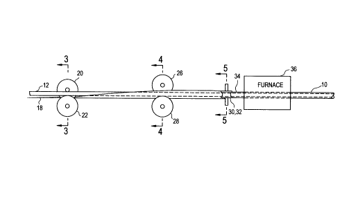
Figure 1 is a~ side view showing processing apparatus used to perform the
inventive method.
Figure 2 is a.n enlarged sectional view showing in an enlarged scale the stock
coated with binding metal before it passes into the dies.
Figure 3 is a sectional view on the line 3-3 of Figure 1 showing the stock
passing through the first set of forming rolls.
Figure 4 is a sectional view on the line 4-4 of Figure 1 showing the stock
passing through the second set of forming rolls.
Figure 5 is a sectional view on the line 5-5 of Figure 1 showing the stock
passing through the final set of forming rolls.
Figure 6 is a cross section through the finished tube.
2
CA 02282143 1999-11-29
Detailed Description of the Invention
The method of the present invention employs an in-line processing mill as
illustrated in Fig. 1. In thc~ process, an inner core tube 12 and a metal
strip or wrap coated
with binding metals 16 are supplied'. simultaneously to the in-line processing
mill. The
coated metal wrap 18 passes through a first set of rollers 20 and 22 which
puts a shoulder
portion in the coated metal wrap. A second set of rollers 26 and 28 curl the
edges of the
coated metal wrap up. A third set of rollers 30 and 32 press the coated metal
wrap in an
overlapping relation around the inner core tube 12. The assemblage 34 of the
inner core
tube 12 and coated wrap 1 f> is then fed either continuously, or in batches,
into a furnace 36
held at the brazing temperature of tile binding metal 16. Brazing causes all
layers to
become integral.
The mufti-wall tube of the present invention is a mufti-wall tube 10
comprising an inner core tube 12 and an outer strip or wrap 18 brazed to the
inner core
tube 12. The inner core tulbe 12 in itself is pressure tight independent of
the outer wrap 18.
Due to variability within the manufacturing process, the seam of the outer
wrap 18 may be
loose or has voids present. Without a pressure tight inner core tube 12
present, the loose
outer seam would be a source of leakage.
This concern is even more evident in the formation of a flare at the end of
the mufti-layer tube. A flare is a ra,dially enlarged flange at the end of a
tube for
connection with a mating component. A flare is formed by hitting the end of
the tube with
3
CA 02282143 1999-11-29
at least one punch, while tile tube is situated in a clamp block. The clamp
block and punch
are both machined to produce the appropriate flare size and shape. A single
flare is formed
with one hit by a single punch. A double flare requires two hits by two
different punches.
To form a double flare, the' first hit by the first punch forms a variation of
the front bead.
The second hit by the second punch folds the tube inwardly and coins the
appropriate angle
on the flare sealing surface. Durin;; the flare forming process, stresses are
formed at the
end of the flare and the fold section of the double flare. These stress areas
have potential
for seam separation and creates a source of leakage.
Concerns for leakage through the seam of the metal wrap 18 are eliminated
with the use of an inner core tube 12 in which itself is pressure tight. The
metal wrap 18,
although enhances fatigue resistance: and pressure containment, is not
critical to leak
integrity of the multi-wall tube 10. This assures 100 % leak integrity solely
to the leak
integrity of the inner core tube 12. Hence, the need to scrap the finished
tube, due to
looseness, separation or void in seam of the metal wrap, is reduced for the
present
invention.
As noted in the backl;round section, prior to the present invention, a mandrel
is necessary to support the outer layer at inside diameter at the finishing
stand. The
mandrel remains stationary while a continuously moving metal stock is wrapped
around the
stationary mandrel. Lubrication between the stationary mandrel and the moving
metal stock
is therefore necessary to reduce the friction between the mandrel and the
metal stock.
4
CA 02282143 1999-11-29
Hence, a by-product of the' mandrel process is the remains of the lubrication
in the inside
diameter of the finished m,ulti-wall tube 10. The use of an inner core tube
12, in place of a
mandrel, to support the tube at its inside diameter during the formation of
the outer wall
layers eliminates the inside diameter cleanliness issue since little, or
possibly no, lubricant
is required in the process.
Moreover, the inner core tube 12, defining the inside diameter of the multi-
wall tube 10, is formed during a separate process from the in-line process
mill. The
cleanliness of the of inside diameter is then independent of the in-line
process mill, but
rather is dependent on the :formation of the inner core tube 12. As long as
inner core tube
is formed in such a manner that its inside diameter is clean, the inside
diameter of the
multi-wall tube 10 would likewise be clean.
The use of an inner core tube 12 in place of a mandrel also eliminates the
downtime required for changing the' mandrel. Although in the prior process
lubricants are
used between the mandrel and the metal stock to reduce friction, wear on the
mandrel still
occurs. Once wear reduce;> the diameter of the mandrel, the inside diameter of
the tube is
also reduced. As a result, the difference between the inside diameter and the
outer diameter
is increased allowing the seam to have voids or looseness. Since voids or
looseness in the
seams are highly undesirable, the mandrel would need to be changed on a
periodic basis
creating downtime in the process. '~~l'he present invention does not use a
stationary mandrel,
s
CA 02282143 1999-11-29
rather, an inner core is fed at the same rate as the metal stock for forming
the outer layer.
Hence, downtimes for changing worn mandrels are eliminated.
Another advantage of using an inner core tube in place of a mandrel is the
elimination of the step of applying <~ carbon lacquer on the assemblage prior
to the heating
stage. If the resultant tube were not supported on either side, upon heating
the assemblage
to the brazing temperature of the binding metal, the binding metal would run
off from the
seam and the assemblage would have a tendency to unwrap. To prevent the
binding metal
from running off, a carbon lacquer is applied to the assemblage prior to the
heating process.
The carbon lacquer has a similar efiFect as oxidizing the binding metal and
solidifies the
binding metal. In addition. due to the dark color of the carbon lacquer, it
also creates a
black body effect allowing the resultant tube to absorb heat more quickly and
evenly.
A tube having a permanent inner core tube, in place of a mandrel for
forming the outer tube, would eliminate the problems associated with the tube
unwrapping
and the need for the black body effect. The metal wrap 18 is supported at the
inside
diameter by the inner tube 12; henc~°, the tendency for the metal wrap
18 to unwrap during
the heating stage is reduced . In addition a process using an inner tube does
not need to
absorb as much heat since the process is more forgiving due the metal wrap 18
supported at
the inner diameter by the inner core tube 12. With the temperature for the
heating process
lower for the present invention than for a process without an inner core tube,
the
6
CA 02282143 1999-11-29
temperature in the furnace would not be high enough to cause the binding metal
12 to run
off.
Suitable tube°s to form inner core tube 12 include single wall
welded steel
tube, single wall welded st;~inless steel tube, single wall seamless steel
tube, single wall
seamless stainless steel tube, brazed double wall tube or mufti-wall tube of
various
constructs described herein. The ir,~ner core tube 12 may be produced by
conventional tube
forming method. The particular process used for forming the inner core tube 12
is not a
part of this invention. The formed inner core 12 can be fed to the outer wall
tube forming
mill in a continuous integrated line immediately after the formation of the
inner core tube.
Alternatively, the formed inner core tube 12 can be accumulated in a coiled
form and then
later fed to the outer layer forming mill.
A side view of the forming mill is shown on Figure 1. Metal strip or wrap
18 is shown in Fig. 2. It is~ cut to appropriate width and coated with a
binding metal 16 on
both sides. Suitable binding metals 16 include copper, nickel, silver braze
alloy or any
combinations of these metals. The metal wrap 18, coated with binding metal 16,
is fed
continuously to the in-line processing mill at the same rate as the inner core
tube 12 is
being fed to the in-line processing mill. At the in-line processing mill,
metal wrap 18
passes between the upper roll 20 and lower roll 22 which puts a shoulder
portion 24 in the
metal stock as shown on Fig. 3. Shoulder 24 is offset to one side of the
center of the metal
wrap 18 such that one side of the wrap is wider than the other side. This
allows the wider
CA 02282143 1999-11-29
side to curl over the narrower portion of the wrap. Thereafter, the metal wrap
18 reaches
rolls 26 and 28 which serve to curl the edges of the metal wrap up as shown on
Fig. 4.
The metal wrap 18 then passes around the core tube 12 and a set of
horizontally-disposed
pressure rolls 30 and 32 serve to press the metal wrap 18 in overlapped
relation around the
core tube 12 as shown on Fig. 5.
The assemblage 34, comprising the inner core tube 12 longitudinally
wrapped with metal wrap 18, is then fed continuously into in a furnace 36 to
the brazing
temperature of the binding metal 16, whereby all layers become integral to
complete the
mufti-wall product of the present invention. Again, the details of the brazing
process are
conventional and well known.
Alternatively, the assemblage 34 can be batch processed by cutting it into 60
to 100 feet length sections ;after the metal wrap 18 is wrapped around the
core tube 12. The
cut sections of the assemblage 34 are then batch heated in a furnace to the
brazing
temperature of the binding metal 16.
A cross-section view of the finished mufti-layer tube product 10 is shown in
FIG. 6. The mufti-layer tube 10 comprises an inner core tube 12, a metal wrap
18 wrapped
around the inner tube 12 and a binding layer 16a between the inner core 12 and
the metal
wrap 18. Located between the metal wrap 18 is another binding metal layer 16b.
The tube
differs from prior tubes because it h.as extra layers construction.
Alternatively, the strip
8
CA 02282143 1999-11-29
could be narrower and onl~r wrapped around once or the strip can be wider and
wrapped
around three times.
Yet another variation of the present invention comprise using a double-wall
tube as the core material rather than a single wall tube. As stated earlier,
the inner core
tube 12 is pressure tight and the metal wrap 18 is not critical to the leak
integrity of the
mufti-walled tube 10. Thus, for the' mufti-wall tube 10 to function
effectively for high
pressure applications, such as diesel tube, a double-wall tube is used in
place of a single
wall tube as the core tube.
Various features of the present invention have been described with reference
to one embodiment. It should be understood that modification may be made
without
departing from the spirit anal scope of the present invention as represented
by the following
claims. For instance, the above embodiment is for the formation of metal strip
18 having
two layers. Depending on the amount fatigue resistance and pressure
containment required
by the resultant tube, the metal strip 18 can be formed of a single layer or
the metal strip 18
can be formed of three or more layers.
9