Note: Descriptions are shown in the official language in which they were submitted.
CA 02282150 1999-09-13
SIDECAR ASSEMBLY FOR A BICYCLE
BACKGROUND OF THE INVENTION
1. Field of the Invention
The present invention relates to sidecars
for bicycles and, more particularly, pertains to a
new sidecar assembly adapted to be readily attached
and detached from a bicycle frame.
2. Description of the Prior Art
Over the years various carrying devices
have been developed for carrying infants and small
children on bicycles. For instance, it has been
proposed to carry infants on child bicycle seats
installed over the rear wheel of the bicycles or,
alternatively, in small trailers drawn behind the
bicycles. One drawback of such carrying devices
resides in the fact that the cyclist cannot view and
easily communicate with the child while riding the
bicycle.
Accordingly, efforts have been made to
design sidecars which are specifically adapted for
use with bicycles. For instance, United States Patent
No. 5,248,158 issued on September 1993 to Ellard and
United States Patent No. 5,292,142 issued on March 8,
1994 to Vitarelli both disclose a sidecar having a
frame structure adapted to be attached to a bicycle
frame by means of a number of interconnected swivel
connections defining a parallelogram-like structural
arrangement allowing the cyclist to lean the bicycle
on either side when making turns. Typically, the
sidecar is attached to the rear axle, the down tube
and the crossbar of the bicycle so as to ensure that
the attachment of the sidecar with the bicycle frame
does not interfere with the operation of the power
train of the bicycle.
Although the sidecars described in the
above mentioned patents allow for the bicycle to lean
- 1 -
CA 02282150 1999-09-13
on either side, it has been found that there is a
need for a new and simpler sidecar which can be
readily connected with and disconnected from a
bicycle frame while still allowing limited relative
motion therebetween.
SUMMARY OF THE INVENTION
It is therefore an aim of the present
invention to provide a sidecar which is adapted to be
easily and quickly connected with and disconnected
from a bicycle frame.
It is also an aim of the present invention
to provide such a sidecar which is relatively simple
and economical to manufacture.
Therefore, in accordance with a general
aspect of the present invention, there is provided a
sidecar for a bicycle having a bicycle frame
extending in a plane and defining a bottom axle
housing for supporting a power train, comprising a
wheeled frame adapted to extend on one side of the
bicycle, a seat provided on the wheeled frame, and a
coupling for attaching the wheeled frame to a bottom
portion of the bicycle frame while allowing relative
pivotal movements of the bicycle frame relative to
the wheeled frame about a longitudinal axis of the
bicycle. The coupling includes a first part which is
fixed relative to the bicycle frame and a second part
which is fixed relative to the wheeled frame. The
first and second parts are rotatably interconnectable
to form with the wheeled frame a system having one
degree of freedom.
In accordance with a further general aspect
of the present invention, there is provided a bicycle
sidecar comprising a frame structure supporting a
seat and having a wheel journaled thereto. The
sidecar further comprises a bracket adapted to be
mounted to a bottom portion of the frame of the
bicycle for projecting forwardly in a direction
- 2 -
CA 02282150 1999-09-13
parallel to a longitudinal axis of the bicycle. The
frame structure includes a structural member having a
first end portion adapted to be slidably engaged and
interlocked with the bracket for solely allowing
limited rotational movements of the bicycle frame
relative to the frame structure about the
longitudinal axis of the bicycle.
BRIEF DESCRIPTION OF THE DRAWINGS
Having thus generally described the nature
of the invention, reference will now be made to the
accompanying drawings, showing by way of illustration
a preferred embodiment thereof, and in which:
Fig. 1 is a perspective view of a sidecar
attached to a bottom portion of a bicycle in
accordance with a first embodiment of the present
invention;
Fig. 2 is a side elevational view of the
sidecar and bicycle of Fig. 1;
Fig. 3 is a front elevational view of the
sidecar with the bicycle leaned at an angle from the
vertical on a side opposed to the sidecar, the front
portion of the bicycle being omitted for clarity
purposes;
Fig. 4 is a front elevational view of the
sidecar with the bicycle leaned at an angle from the
vertical towards the sidecar, the front portion of
the bicycle being omitted for clarity;
Fig. 5 is an enlarged fragmentary side view
of the connection between the sidecar and the
bicycle; and
Fig. 6 is a cross-sectional view taken
along line 6-6 in Fig. 5.
DESCRIPTION OF THE PREFERRED EMBODIMENTS
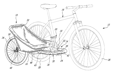
Referring now the Fig. 1, there is shown a
sidecar 10 attached to a side of a bicycle 12 via a
single coupling 14. The bicycle 12 is of conventional
construction and comprises among other elements a
- 3 -
CA 02282150 1999-09-13
frame 16 defining a bottom axle housing 18 from which
a pair of laterally spaced-apart chain stays 19
extend rearwardly. The bottom axle housing 18 is
adapted to support a power train 20 including a chain
sprocket 22 which can be operated via a pair of
pedals 24 to propel the bicycle 10, as is well known
in the art . The bicycle frame 16 is supported on the
ground by front and rear wheels 26 and 28.
The sidecar 10 generally comprises a frame
30, a seat 32 rigidly mounted on the frame 30, and a
wheel 34 journaled to the rear end of the frame 30.
The seat 32 is generally centered over the wheel 34.
The frame 30 is composed of a single
support or structural member 36 provided in the form
of a U-shaped tube. The structural member 36
comprises first and second parallel linear portions
38 and 40 interconnected by a laterally bent portion
42.
As seen in Fig. 2, the seat 32 is mounted
on a support plate 44 having an undersurface on which
a pair of spaced-apart parallel transversal members
46 are screwed. The transversal members 46 are welded
to the linear portion 40 of the structural member 36
in order to secure the seat 32 thereto.
The wheel 34 has an axle 48 which is
journaled in a block 50 secured to the rear end of
the structural member 36 via a number of threaded
fasteners 52.
As seen in Figs. 3 and 4, the connection
between the sidecar 10 and the bicycle 12 enables the
cyclist to lean the bicycle 12 on either side between
first and second limits positions, without affecting
the position of the sidecar 10.
More specifically, as seen in Figs. 5 and
6, the coupling 14 includes a bracket 54 which is
detachably securable between the chain stays 19 of
the bicycle frame 16. The bracket 54 includes a top
- 4 -
CA 02282150 1999-09-13
member 56 adapted to be seated on the chain stays 19
and a bottom member 58 adapted to be held against the
undersurface of the chain stays 19 and the bottom
axle housing 18. A number of threaded fasteners 60
are provided to retain and draw the top and bottom
members 56 and 58 towards each other against the
chain stays 19 so as to rigidly attach the bracket 54
to the bicycle frame 16. The bracket 54 can be
readily removed from the bicycle frame by unscrewing
the threaded fasteners 60 so as to disconnect the
bottom member 58 from the top member 56. According to
the illustrated embodiment, the top member 56 is
provided in the form of a single plate, whereas the
bottom member 58 is provided in the form of a pair of
perpendicular plates 62 and 64 welded together.
As seen in Figs. 2 and 5, an axle 66
extends forwardly from the plate 62 just below the
plate 64 to a position in front of the bottom axle
housing 18. The axle 66 is disposed so as to be
coaxial with the central longitudinal axis of the
bicycle frame 16. The proximal end of the axle 66 is
secured to the plate 62 as by welding. Furthermore,
the axle 66 can be welded, such as at 68, to the
undersurface of the plate 64 in order to increase the
bearing capacities of the axle 66. In the illustrated
embodiment, the axle 66 has a tubular body.
As seen in Fig. 5, the linear portion 38 of
the tubular structural member 36 is dimensioned to be
slidably fitted over the distal end portion of the
axle 66. A circumferential slot 70 is defined in the
linear portion 38 of the structural member 36 for
receiving a pin 72 adapted to be rigidly connected to
the axle 66 so as to prevent axial removal of the
structural member 36 from the axle 66, while at the
same time allowing limited relative rotational
movements therebetween. As depicted by arrow 74 in
Fig. 6, the pin 72 will be constrained to move within
_ 5 _
CA 02282150 1999-09-13
the circumferential slot 70 between opposed limits
positions 72' and 72' ' in response to the tilting of
the bicycle frame 16 from the vertical. It is noted
that the pin 72 will be disposed midway between the
opposed ends of the circumferential slot 70 when the
bicycle will stand upright. Accordingly, the sideways
tilting of the bicycle frame 16 will be equally
limited on either side from the vertical by the
opposed ends of the circumferential slots 70.
The pin 72 can be threadably engageable
with the axle 66 or otherwise releasably secured
thereto.
As seen in Figs . 1 and 2 , the f first linear
portion 38 of the structural member 36 is dimensioned
to extend forwardly in front of the bottom axle
housing 18 behind the front wheel 26 at a sufficient
distance to ensure that the laterally bent portion
42, which extends laterally from the first linear
portion 38, will not interfere with the path defined
by the pedals 24 when operated to propel the bicycle
12. The second linear portion 40 of the structural
member 36 extends rearwardly from the laterally bent
portion 42 along one side of the bicycle 12. The
lateral spacing between the second linear portion 40
and the bicycle frame 16 is determined by the length
of the laterally bent portion 42 interconnecting the
first and second linear portions 38 and 40 to one
another.
One major advantage of the present
invention resides in the fact that the sidecar 10 can
be easily and quickly coupled to the bicycle frame 16
by first slidably fitting the linear portion 38 of
the structural member 36 over the axle 66 to a
position where the circumferential slot 70 is in
register with a threaded radial bore (not shown)
defined through the axle 66, and second threadably
engaging the pin 72 within the threaded radial bore.
- 6 -
CA 02282150 1999-09-13
To disconnect the sidecar 10 from the bicycle 12, one
only has to disengage the pin 72 from the axle 66 and
axially withdraw the structural member 36 from the
axle 66.
Furthermore, the present invention is
simple and economical to manufacture.
According to a second embodiment of the
present invention which is not illustrated, the
laterally bent portion 42 could extend rearwardly in
diagonal with respect to the longitudinal axis of the
bicycle 12 and the seat 32 could be mounted centrally
thereon, thereby eliminating the need of having
transversal members 46 for securing the seat 32 on
the structural member 36. Furthermore, the wheel 34
could be selectively mounted on either side of the
rear end of the linear portion 40 of the structural
member 36 so as to be centrally or laterally disposed
relative to the seat 32 depending on the weight of
the child to be carried.
According to a further embodiment of the
present invention, a pair of circumferentially
spaced-apart stoppers (not shown) could be provided
on the axle 66 at a proximal end portion thereof to
receive therebetween a projection (not shown)
extending from the free end of the linear portion 38
of the structural member 36. The stoppers would
cooperate with the projection to limit relative
rotational movement between the structural member 36
and the axle 66.