Note: Descriptions are shown in the official language in which they were submitted.
CA 02282248 1999-09-15
1
TITLE OF THE INVENTION:
Machine For Use In Recycling Armoured Cable
NAMES) OF INVENTOR(S):
Kenneth Allen Pederson
FIELD OF THE INVENTION
The present invention relates to a machine for use in
recycling armoured cable.
BACKGROUND OF THE INVENTION
Armoured cables are used in numerous industrial
applications. One example of such an industrial application
is the connection of submersible pumps used by the oil industry
in oil well installations to pump oil to surface.
There are many different styles of armoured cable. They
usually have several conductive wires of material known to be
a good conductor of electricity, such as copper. Each of the
several conductive wires has at least one protective layer,
usually rubber or polymer plastic. Some styles of armoured
cable have an additional protective layer of lead. The
conductive wires are found within a protective armour casing
of metal or polymer plastic.
Recycling of armoured cables involves separating the
conductive wire from the protective layer and from the casing
and recovering the various materials out of which the armoured
cable is made. At the present time the majority of this work
is done manually. It has proven to be labour intensive work.
SUN~IARY OF THE INVENTION
What is required is a machine that will assist in
separating the materials out of which armoured cable is made
for the purpose of recycling.
According to the present invention there is provided a
CA 02282248 1999-09-15
2
machine for use in recycling armoured cable which includes a
support having a first end and a second end. The support
defines a processing stream that starts at the first end and
continues downstream toward the second end. A single primary
splitter knife is mounted at the first end of the support. At
least one separating wedge is positioned downstream of the
splitter knife. Several secondary splitter knives are
positioned downstream of the separating wedge. A stripper
plate is positioned downstream of the secondary splitter
knives. The stripper plate has several apertures. Each of the
several apertures is sized just large enough to accommodate one
of several conductive wires of the armoured cable. A rotatably
mounted collection drum is positioned downstream of the
stripper plate. A drive motor is provided for rotating the
collection drum with each of the several conductive wires
attached. The armoured cable is split open as it is drawn past
the primary splitting knife. The armoured cable is separated
into an armoured casing and several conductive wires when it
is drawn past the separating wedge. The several conductive
wires are split open as they are drawn past the secondary
splitting knives. Protective covering is stripped from the
conductive wires as they are drawn through the apertures of the
stripping plate . The conductive wires are wound around the
collection drum as the collection drum continues to rotate.
The machine described above provides a mechanized process
for separating the materials out of which armoured cable is
made for the purpose of recycling.
While there may be other types of splitting knives that
can be used for the primary splitting knife and the secondary
splitting knives, beneficial results have been obtained through
the use of a rotating guide pulley with a peripheral guide
channel and a rotating circular blade with a peripheral cutting
edge. The rotating circular blade bears a resemblance to a
pizza knife. The peripheral cutting edge is aligned on a
common plane with the peripheral guide channel. It is
CA 02282248 1999-09-15
3
preferred that a relative position of the guide pulley and the
circular blade is adjustable within the common plane to provide
control over the depth the peripheral cutting edge of the
circular blade will impinge upon the armoured cable when it is
positioned in the peripheral guide channel of the guide pulley.
This allows the splitting knife to be adjusted to suit
differing thicknesses of armoured casing.
While there may be other types of wire strippers that can
be used to remove the protective coverings from the conductive
wire, beneficial results have been obtained through the use of
a stripper plate. It is preferred that the stripper plate have
several guide slots and several floating aperture plates
coupled with the guide slots . This enables the aperture plates
to move along the guide slots in response to angular feed
changes caused by a dynamically changing diameter for the
collection drum as conductive wires are wound onto the
collection drum.
BRIEF DESCRIPTION OF THE DRAWINGS
These and other features of the invention will become more
apparent from the following description in which reference is
made to the appended drawings, wherein:
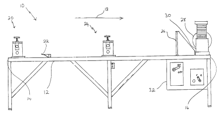
FIGURE 1 is a side elevation of a machine for use in
recycling armoured cable constructed in accordance with the
teachings of the present invention.
FIGURE 2 is a top plan view of the machine for use in
recycling armoured cable illustrated in FIGURE 1.
FIGURE 3 is a front elevation view of a primary splitting
knife from the machine for use in recycling armoured cable
illustrated in FIGURE 1.
FIGURE 4 is a front elevation view of a series of
secondary splitting knives from the machine for use in
recycling armoured cable illustrated in FIGURE 1.
FIGURE 5 is a rear elevation view of a collection drum and
stripper plate from the machine for use in recycling armoured
cable illustrated in FIGURE 1.
CA 02282248 1999-09-15
4
FIGURE 6 is a detailed rear elevation view of the stripper
plate illustrated in FIGURE 5.
DETAILED DESCRIPTION OF THE PREFERRED EMBODIMENT
The preferred embodiment, a machine for use in recycling
armoured cable generally identified by reference numeral 10,
will now be described with reference to FIGURES 1 through 6.
Referring to FIGURES 1 and 2, machine 10 for use in
recycling armoured cable has a support 12 having a first end
14 and a second end 16. Support 12 defines a processing stream
that starts at first end 14 and continues downstream toward
second end 16, the direction of which is indicated by arrow 18.
The purpose of machine 10 is to separate armoured cable into
its components. This will generally include the conductive
material of each wire, usually copper; the protective layer for
each wire, usually polymer plastic; and the protective armour
casing, usually metallic. A single primary splitter knife 20
is mounted at first end 14 of support 12, downstream from which
are, in sequence, at least one separating wedge 22, a secondary
splitter knives holder 24, a stripper plate 26 and, finally,
a rotatably mounted collection drum 28 at second end 16 of
support 12. A drive motor 30 is provided for rotating
collection drum 28. Referring to FIGURE l, controls 32 are
provided for controlling the supply of power to drive motor 30
and the direction of rotation of collection drum 28.
Referring to FIGURE 3, primary splitting knife 20 has a
rotating guide roller 33 and a rotating circular blade 38 with
a peripheral cutting edge 40. A relative position of guide
roller 33 and circular blade 38 is adjustable using manually
adjustment screw jacks 41 within common plane, indicated by
arrow 42, to provide control over the depth peripheral cutting
edge 40 of circular blade 38 impinges upon armoured cable when
it passes over guide roller 33.
Referring to FIGURE 4, several secondary splitter knives
CA 02282248 1999-09-15
44 are mounted in secondary splitter knives holder 24.
Secondary splitter knives 44 are of similar construction to
primary splitting knife 20. Each of secondary splitter knives
44 has a guide pulley 34 mounted on guide roller 33. Each
5 guide pulley 34 has a peripheral guide channel 36 which
accommodates a single strand of coated wire. Each of secondary
splitter knives 44 also has a rotating circular blade 38 with
peripheral cutting edge 40. Circular blade 38 is aligned so
that peripheral cutting edge 40 is aligned with peripheral
guide channel 36 of guide pulley 34. As previously described,
the relative position of guide pulleys 34 and circular blades
38 is adjustable using manually adjustment screw jacks 41
within common plane 42, to provide control over the depth
peripheral cutting edge 40 of circular blade 38 impinges upon
a single strand of coated wire as passes over peripheral guide
channel 36 of guide pulley 34.
Referring to FIGURE 6, stripper plate 26 has a top edge
46, a bottom edge 48, and opposed sides 50. Several guide
slots 52 extend vertically from bottom edge 48 toward top edge
46. A floating aperture plate 54 is associated with each of
guide slots 52. Each aperture plate 54 moves along guide slot
52 to which it is coupled in response to angular feed changes.
Each of the several floating aperture plates 54 has an aperture
56 sized large enough to accommodate a single strand of
conductive wire, but not any protective coating on the
conductive wire.
The method of use of machine 10 for use in recycling
armoured cable will now be described with reference to FIGURES
1 through 6. Referring to FIGURE 2, to prepare machine 10 for
operation armoured cable 100 is first split manually into an
armour casing 102 and three coated wires 104. Armoured cable
100 is fed into primary splitting knife 20. Armour casing 102
and coated wires 104 are passed on opposed sides of separating
wedge 22. Coated wires 104 are then each fed separately into
one of secondary splitting knives 44 of secondary splitter
CA 02282248 1999-09-15
6
knives holder 24. Each of coated wires 104 is then split into
a protective layer 106 and conductive wire 108. Conductive
wire 108 is fed through one of apertures 56 in floating
aperture plates 54 of stripper plate 26. The conducting wire
is then secured onto collection drum 28. Machine 10 is thus
prepared for operation to process a length of armoured cable
100. Drive motor 30 is started, and collection drum 28, with
each of the several conducting wires 108 attached, is rotated.
Armoured cable 100 is thereby drawn in direction 18 along
support 12 and sequentially processed by primary splitting
knife 20, separating wedge 22, secondary splitting knives 44,
and stripper plate 26. Referring to FIGURE 3, at primary
splitting knife 20 armoured cable 100 is split open. Referring
to FIGURE 3, at separating wedge 22 armour casing 102 of
armoured cable 100 is separated and falls into a collection
area while coated wires proceed downstream for further
processing. Referring to FIGURE 4, at secondary splitting
knives 44 each of coated wires 104 is split open. Referring
to FIGURE 2, conductive wire 108 passes through apertures 56
in stripper plate 26 and onto collection drum 28. Protective
layer 106 is unable to pass through apertures 56 and falls into
a collection area. As the amount of material on collection
drum increases, the feed angle from apertures 56 to collection
drum is altered. This change in feed angle is accommodated by
floating aperture plates 54 which are drawn to the appropriate
level along slots 52 by the forces exerted upon conductive wire
108. Collection drum 28 periodically becomes full, and an
empty collection drum 28 is then substituted. As one armoured
cable 100 is completed processing, it can be attached to the
next armoured cable to be processed, thereby drawing the next
armoured cable through. If care is taken in substituting
collection drum 28 and in attaching the end of one armoured
cable to the end of the next armoured cable, the need to
manually feed the machine can be avoided.
It will be apparent to one skilled in the art that
modifications may be made to the illustrated embodiment without
CA 02282248 1999-09-15
departing from the spirit and scope of the invention as
hereinafter defined in the Claims.