Note: Descriptions are shown in the official language in which they were submitted.
CA 02282546 2005-08-04
~ I
METHOD AND APPARATUS FOR TREATING VENOUS INSUFFICIENCY
USING DIRECTIONALLY APPLIED ENERGY
BACKGROUND OF THE TNVENTION
The invention relates generally to the treatment and correction of venous
insufficiency,
and more particularly, to a minimally invasive procedure and apparatus using a
catheter-based
system having an energy-delivery arrangement for providing energy
intraluminally to shrink a.:-
vein to change the fluid flow dynamics, and to restore the competency of
venous valves thereby
restoring the proper function of the vein.
The human venous system of the lower limbs consists essentially of the
superficial
venous system and the deep venous system with perforating veins connecting the
two systems.
The superficial system includes the long or great saphenous vein and the short
saphenous vein.
The deep venous system includes the anterior and posterior tibial veins which
unite to form the
popliteal vein, which in turn becomes the femoral vein when joined by the
short saphenous vein.
The venous systems contain numerous one-way valves for directing blood flow
back
to the heart. Venous valves are usually bicuspid valves, with each cusp
forming a sack or
reservoir for blood which, under retrograde blood pressure, forces the free
surfaces of the cusps
together to prevent retrograde flow of the blood and allows only antegrade
blood flow to the
heart. When an incompetent valve is in the flow path, the valve is unable to
close because the
cusps do not form a proper seal and retrograde flow of blood cannot be
stopped.
Incompetence in the venous system can result from vein dilation. Separation of
the
cusps of the venous valve at the commissure may occur as a result, thereby
leading to
incompetence. Another cause of valvular incompetence occurs when the leaflets
are loose and
floppy. Loose leaflets of the venous valve results in redundancy which allows
the leaflets to
fold on themselves and leave the valve open. The loose leaflets may prolapse,
which can allow
reflux of blood in the vein. When the venous valve fails, there is an
increased strain and
pressure on the lower venous sections and overlying tissues, sometimes leading
to additional
CA 02282546 1999-08-27
WO 98/38936 PCT/US98/02247
2
valvular failure. Two venous conditions which often involve vein dilation are
varicose veins and
more symptomatic chronic venous insufficiency.
The varicose vein condition includes dilatation and tortuosity of the
superficial veins of
the lower limbs, resulting in unsightly discoloration, pain, swelling, and
possibly ulceration.
Varicose veins often involve incompetence of one or more venous valves, which
allow reflux
of blood within the superficial system. This can also worsen deep venous
reflux and perforator
reflux. Current treatments include surgical procedures such as vein stripping,
ligation, and
occasionally, vein segment transplant, venous valvuloplasty, and the
implantation of various
prosthetic devices. The removal of varicose veins from the body can be a
tedious, time-
consuming procedure having a painful and slow healing process. In addition,
patients with
varicose veins may undergo injection sclerotherapy, or renioval of vein
segments.
Complications, scarring, and the loss of the vein for future cardiac and other
by-pass procedures
may also result. Aloriy, with the complications and risks of invasive surgery,
varicose veins may
persist or recur, particularly when the valvular problem is not corrected. Due
to the long,
technically demanding nature of the surgical valve reconstruction procedure,
treating multiple
venous sections with surgical venous valve repair is rarely performed. Thus, a
complete
treatment of all important incompetent valves is impractical.
Non-obstructive chronic venous insufficiency (CVI) is a problem caused by
degenerative
weakness in the vein valve segment, or by hydrodynamic forces acting on the
tissues of the
body, especially the legs, ankles and feet. As the valves in the veins fail,
the hydrostatic
pressure increases on the next venous valves down, causing those veins to
dilate. As this
continues, more venous valves will eventually fail. As they fail, the
effective height of the
column of blood above the feet and ankles grows, and the weight and
hydrostatic pressure
exerted on the tissues of the ankle and foot increases. When the wei,ht of
that column reaches
a critical point as a result of the valve failures, ulcerations of the ankle
begin to form, which
start deep and eventually come to the surface. These ulcerations do not heal
easily because of
poor venous circulation due to valvular incompetence in the deep venous system
and other vein
systems.
Chronic venous insufficiency often consists of hypertension of the lower licnb
in the
deep, perforating and often superficial veins, and may result in
discoloration, pain, swelling and
ulceration. Existing treatments for chronic venous insufficiency are often
less than ideal. These
SUBSTITUTE SHEET (RULE 26)
.._. .. ..._.... ... ._. . . . .. T ._.... .. _... ... _.. . _ _ . . t
CA 02282546 1999-08-27
WO 98/38936 PCTIUS98/02247
3
treatments include the elevation of the legs, compressing the veins externally
with elastic
support hose, perforator ligation, surgical valve repair, and grafting vein
sections with healthy
valves from the arm into the leg. These methods have variable effectiveness.
Moreover,
invasive surgery has its associated complications with risk to life and
expense. Similarly, the
palliative therapies require major lifestyle changes for the patient. For
example, the ulcers may
recur unless the patient continues to elevate the legs and use pressure
gradient stockings for
long continuous periods of time.
Due to the time-consuming and invasive nature of the current surgical
treatments, such
as valvuloplasty or vein segment grafting, typically only one valve is treated
during any single
procedure. This greatly limits the ability of the physician to fiilly treat
patients suffering from
chronic venous insufficiency. Every instance of invasive sur,ery, however, has
its associated
complications with morbidity and expense.
Another type of treatmerit, the ligation of vascular lumina by cauterization
or
coagulation using electrical energy froni an electrode, has been employed as
an alternative to
the surgical removal of superficial and perforator veins. However, such
ligation procedures also
close off the lumen, essentially destroying its functional capability. For
example, it is known
to introduce an electrode into the leg of a patient, and position the
electrode adjacent the
exterior of the varicose veins to be treated. Through a small stab incision, a
probe is forced
through the subcutaneous layer between the fascia and the skin, and then to
the various veins
to be destroyed. A rnonopolar electrode at the outer end of the probe is
placed adjacent the
varicose vein and ttie return electrode is placed on the skin. Once properly
positioned, an
alternating current of 500 kiloHertz is applied to destroy the adjacent
varicose veins by
electrocoagulation. The coagulated veins lose the function of allowing blood
to flow through,
and are no longer of use. For example, occluding or ligating the saphenous
vein would render
that vein unavailable for harvesting in otlier surgical procedures such as
coronary by-pass
operations.
An approach used to shrink a dilated vein involves the insertion of a catheter
that
provides RF or other energy to the vein tissue. The amount of energy imparted
is controlled
so that shrinkage occurs as desired. However, one such device is substantially
omni-directional
in nature and does not permit the application of energy to only a selected
portion of the vein.
The directional application of'energy from such a catheter to affect only a
selected portion of
SUBSTITUTE SHEET (RULE 26)
CA 02282546 1999-08-27
WO 98/38936 PCTIUS98/02247
4
the tissue would be particularly useful in the case wliere one desires to
shrink only the valve
commissures and not the remainder of the vein, as an example.
Thus a need exists in the art to treat dilated veins, such as those resulting
in varicose
veins or from venous insufficiency, to maintain the patency of the veins for
venous function, and
to restore incompetent valves to valvular competency. Those skilled in the art
have recognized
a need to be able to provide energy directionally so that only selected
portions of tissue are
affected. The invention fulfills these needs and others.
SUMMARY OF THE INVENTION
Brietly, and in general terms, the present invention provides a minintally
invasive method
and apparatus for solving the underlying problems of venous insufl'iciency and
uses a novel
repair system, including a directional energy delivery catheter for applying
energy to a selected
tissue site. A metliod for venous repair coniprises the steps of introducing a
catheter having
a working end and nieans for applying energy located at the working end to a
treatment site in
the vein lumen; positioning the means for heating adjacent the treatment site
in the vein lumen;
directionally emitting energy from the means for heating to selectively heat
the treatment site
and cause shrinkage of venous tissue at the treatment site; and terminating
the emission of
energy from the means for heating after sufficient shrinkage to restore vein
competency. An
apparatus for applying energy to cause shrinkage of a vein comprises a
catheter having a shaft,
an outer diameter and a working end, wherein the outer diameter of the
catheter is less than the
outer diameter of the vein; and an energy delivery apparatus located at the
working end to
impart energy to the venous tissue. In one aspect, the energy delivery
apparatus comprises at
least two electrodes located at the working end of the catheter, wherein the
electrodes produce
an RF field to directionally heat a venous treatment area adjacent the
electrode to cause
preferential shrinkage of the vein. The energy is applied to a selected
circumferential portion
of the vein to achieve a reduction of the diameter of the vein.
In another aspect of the invention, an optical energy source may be used to
impart
directional energy to selectively heat venous tissue.
An aspect of the present invention is to provide an apparatus and method for
restoring
valvular competence by selectively shrinking the otherwise dilated lumen of
the vein by
directionally applying energy to tissue.
SUBSTITUTE SHEET (RULE 26)
, ,
CA 02282546 1999-08-27
WO 98/38936 PCT/US98/02247
Another aspect of the present invention is to provide an apparatus and method
for
controllably shrinking loose, floppy valve leaflets in incompetent valves by
directionally
applying energy in order to restore valvular competence.
Another aspect of the present i.nvention is to provide an apparatus and method
which
5 can treat multiple venous sites in a single procedure.
An additional aspect of the present invention is that no foreign objects or
prothesis
remain in the vasculature af3er treatment.
These and other aspects and advantages of the present invention will become
apparent
from the following more detailed description, when taken in conjunction with
the accompanying
drawings which illustrate, by way of example, the preferred enibodiments of
the invention.
BRIEF DFSCRIPTInN OF THE DRAWINGS
FIGURE 1 is a cross-section view Ot'venous insufliciency in a lower limb
showing both
dilatation of the vein and multiple incompetent valves which is to be treated
in accordance with
the present invention,
FIG. 2 is a representative view of a venous section having an incompetent
valve taken
along lines 2-2 of FIG. I which is being treated at one comniissure by a
catheter having an
electrode pair, in accordance with aspects of the present invention;
FIG. 3 is a representative view of the venous section shown in FIG. 2 which is
being
treated at the opposite commissure by the same electrode-pair catheter, in
accordance with
aspects of the present invention;
FIG. 4 is a cross-sectional view of treatment of the leaflets of the valve of
FIGS. 2 and
3 in accordance witli aspects of the present invention;
FIG. 5 is a cross-sectional view of the valve of FIGS. 2, 3 and 4 after
successful
treatment showing that it is once again competent;
FIG. 6 is a partial cross-sectional plan view of an embodiment of the catheter
having an
electrode pair and incorporating aspects of the present invention;
FIG. 7 is a cross-sectional view of the embodiment of the catheter
incorporating aspects
of the invention of FIG. 6 taken along lines 7-7;
FIG. 8 is an end view of the embodiment of the catheter of FIG. 6 in
accordance with
aspects of the invention,
SUBSTITUTE SHEET (RULE 26)
CA 02282546 1999-08-27
WO 98/38936 PCT/US98/02247
6
FIG. 9 is an end view of another embodiment of a catheter in accordance with
aspects
of the present invention;
FIG. 10 is yet another view of another embodiment of a catheter having two
electrodes
in accordance with aspects of the present invention;
FIG. 1l is a diagram of a directional RF energy system with a catheter having
deployable electrodes for directionally imparting energy to a vein;
FIG. 12 is an enlarged side view of the working end of the embodiment of the
directional catheter shown in FIG. 1 1 showing the bowable electrodes,
temperature sensors,
guide wire, and stop surface arrangement, in accordance with aspects of the
present invention;
FIG. 13 is a partial cross-sectional view of a bowable electrode of the
catheter taken
across lines 1 3-13 in FIG. 12 in accordance with aspects of the present
invention;
FIG. 14 is a schematic view of niountini, deployable discrete electrode pairs
so that they
remain the same distance apart when they liave been expanded;
FIG. 15 is a flux diagram showing the arrangement of discrete electrode pairs
to achieve
directionality and also shows the primary flux lines resulting from the
arrangement;
FIG. 16 is a representative side view of a valve of a venous section being
treated by the
embodiment of the catheter of FIG. 11 in accordance with aspects of the
present invention;
FIG. 17 is a front cross-sectional view of the commissures of the venous
section being
treated by the embodiment of the catheter of FIG. I 1 in accordance with
aspects of the present
invention;
FIG. 18 is a front cross-sectional view of the leaflets of the valve ofthe
venous section
being treated by the embodiment of the catheter of FIG. 1 1 in accordance with
aspects of the
present invention;
FIG. 19 is a side view of another embodiment of a catheter having one pair of
bowable
electrodes in accordance with aspects of the present invention;
FIG. 20 is a side view of another embodiment of a catlieter having a balloon
formed on
the catheter shaft opposite one pair of electrodes in accordance with aspects
of the present
invention;
FIG. 21 is a representative view of a venous section having an incompetent
valve which
is being treated at one commissure by a catheter having an electrode pair (not
shown) and an
SUBSTITUTE SHEET (RULE 26)
r ,
CA 02282546 1999-08-27
WO 98/38936 PCT/US98/02247
7
inflated balloon opposite the electrode pair to position the electrode pair in
apposition with the
commissure, in accordance with aspects of the present invention;
FIG. 22 is a view similar to FIG. 21 showing the electrode pair of the
catheter of FIG.
21 positioned in apposition with the opposite commissure by the inflated
balloon, in accordance
with aspects of the present invention,
FIG. 23 is a cross-sectional view of treatment of a leaflet of the valve of
FIGS. 21 and
22 in accordance witli aspects of the present invention where the balloon has
once again been
inflated to position the electrode pair as desired;
FIG. 24 is a view of a competent valve resulting from the activity shown in
FIGS. 21
through 23, and
FIG. 25 is a view of an alternate embodiment of a directional catheter in
which optical
energy is directionally applied to the vein wall to cause shrinkas;e.
DETAILED DESCRIPTION OF THE PREFERRED EMBODIMENTS
Turning now to the drawings with niore particularity, the invention is
embodied in a
system and metliod for the intravenous treatment of veins using a catheter to
deliver an energy-
application element, such as a pair of electrodes, to a venous treatment site.
Although
described as applying RF energy from the electrode, it is to be understood
that other forms of
energy such as microwaves, ultrasound, direct current, circulating heated
fluid, optical energy,
radiant light, and LASERs may be used, and that the thermal energry generated
from a resistive
coil or curie point element may be used as well. As used herein, like
reference numerals will
designate corresponding or similar elements in the various embodiments ofthe
present invention
to be discussed. In addition, unless otherwise noted, the term "working end"
will refer to the
direction toward the treatment site in the patient, and the term "connecting"
end will refer to
the direction away from the treatment site in the patient. The following
embodiments are
directed to the treatment of the venous system of the lower limbs. It is to be
understood,
however, that the invention is not limited thereto and can be employed
intraluminally to treat
veins in other areas of the body such as hemorrhoids, esophageal varices, and
venous-drainage-
impotence of the penis.
A partial cross-sectional view of a dilated vein 10 from a lower limb having
incompetent
valves is shown in FIG. 1. These veins are often disposed within muscle
tissue. Veins have
SUBSTITUTE SHEET (RULE 26)
CA 02282546 1999-08-27
WO 98/38936 PCT/US98/02247
8
bicuspid valves, and in a normal and competent valve 12, as shown in the upper
part of the vein,
each cusp forms a sack or reservoir 14 for blood which, under pressure, forces
the free edges
of the cusps together to prevent retrograde flow of the blood and allow only
antegrade flow to
the heart. The arrow 16 leading out the top of the vein represents the
antegrade flow of blood
back to the heart. The venous valves prevent retrograde flow as blood is
pushed forward
through the vein lumen and back to the heart.
When an incompetent valve 18, such as those shown in the lower part of the
vein,
encounters retrograde flow, the valve is unable to close, the cusps do not
seal properly, and
retrograde flow of blood may occur. Incompetent valves may result from the
stretching of
dilated veins. As the valves fail, increased pressure is imposed on the lower
veins and the lower
valves of the vein, which in turn exacerbates the failure of these lower
valves. The valve cusps
can experience separation at the commissure due to the thinning and stretching
of the vein wall
at the cusps. Valves can also become incompetent as a result of loose, floppy
valve leaflets that
can prolapse in response to retrograde blood flow or high proximal venous
pressure.
A method of minimally invasive treatment of venous insufficiency and valvular
incompetency inciudes utilizing a catheter to deliver bipolar electrodes, to a
venous treatment
site. A cross-sectional perspective view of a dilated vein taken along lines 2-
2 of FIG. 1 is
illustrated in FIG. 2. The electrodes directionally provide RF energy at the
working end of the
catheter to heat and shrink selected venous tissue between the electrodes. The
directional
application of RF energy in effect forms a heating zone along a portion of the
catheter, and
allows for localized or preferential heating of venous tissue so that
shrinkage of the venous
tissue can be limited to selected areas of the vein, such as the conunissures
of venous valves to
restore venous valvular competency. For example, the venous tissue at the
commissures can
be heated, and the resulting shrinkage can bring the cusps of the venous valve
closer together
to restore competency. Further shrinkage of the cusps and leaflets can be
achieved, if
necessary, by moving or rotating the catheter and applying RF energy
directionally to the
leaflets to cause localized preferential heating and shrinkitig of the valve
leaflets. The outcome
of this directional application of RF energy is similar in effect to
surgically placing reefing
sutures into a floppy valve leaflet during venous valvuloplasty surgery.
Selectively heating a circumferential portion of the vein results in
controlled shrinkage
of the vein while avoidiiig the application of energy to the entire vein wall.
By the method and
SUBSTITUTE SHEET (RULE 26)
T . .. ...... .._ , . ... .. .. ........ T.. . . ~
CA 02282546 1999-08-27
WO 98/38936 PCT/US98/02247
9
apparatus disclosed, the entire vein wall need not be subjected to heating
energy, yet shrinkage
of the vein diameter can be effected.
An embodiment of the catheter 20 having a working end 22 having a pair of
electrodes
for 24 and 26 causing localized heating of the surrounding venous tissue and
shrinkage of the
vein is illustrated in FIGS. 2 through 6. This and other embodiments of the
catheter 20 will be
described in greater detail later. The working end 22 includes electrodes 24
and 26 for
providing RF energy to form a localized heating zone in the tissue at and
between the
electrodes. The electrodes 24 and 26 can be conductive strips, plates, or
wires embedded in
the working end 22 of the catheter. RF energy conducted between the electrodes
24 and 26
through contacting venous tissue causes that tissue and surrounding adjacent
venous tissue to
be heated and shrink. The RF energy is directional between the electrodes of
the catheter, and
can be directionally applied to the surrounding venous tissue, including the
commissures, cusp
and leaflets of the venous valves, or to a specific radial arc of the vein
wall.
The method of the present invention for the minimally invasive treatment of
venous
insufficiency preferably uses RF electrodes and a delivery catheter to restore
the competency
of a vein. Alternatively, the method is contemplated to be used with any
suitable appliance for
directionally applying radiant energy or heat in the repair or reconfiguration
of incompetent
veins. The electrodes for generating the heating effect for shrinking the
surrounding venous
tissue can be introduced either antegrade or retrograde. Particular discussion
will be made of
the treatment of varicose veins in the legs, though the method is well suited
to treating veins
in other areas of the body.
When treating the veins of the lower limbs, the patient is typically placed
onto a
procedure table with the feet dependent in order to fill the veins of the leg.
The leg of the
patient is prepped with antiseptic solution. A percutaneous introducer is
inserted into the vein
using a common Seldinger technique to access the saphenous or deep vein
system.
Alternatively, a venous cut-down can be used to access the vein system to be
treated. The
procedure for the repair of incornpetent veins can be accomplished by a
qualified physician with
or without fluoroscopic or ultrasonic observation, or under direct
visualization. Further, the
physician could palpate the treatment area to determine the location of the
catheter, and the
treatment site, during the procedure when treating the superficial venous
system. The physician
SUBSTITUTE SHEET (RULE 26)
CA 02282546 1999-08-27
WO 98/38936 PCT/US98/02247
may also palpate the vein into apposition with the electrodes to achieve good
contact between
the electrodes and the vein wall.
The delivery catheter 20 could be passed within the vein after insertion
through the skin.
Altematively, a guide wire for the catheter can be inserted into the vein. The
wire is advanced
5 antegrade to the level of the most proximal incompetent vein valve which is
to be repaired. The
delivery catheter is then inserted upon the wire and is fed up the leg through
the vein to the
level of the dilated venous section to be treated. Fluoroscopy, ultrasound, or
an angioscopic
imaging technique is then used to direct the specific placement of the
catheter and confirm the
position within the vein. Contrast material can be injected through or around
the catheter to
10 identify the incompetent venous sections to be repaired. A retrograde
venogram can be
performed in some cases to better localize the treatment site and effect.
From the antegrade approach, ttie catheter can be placed adjacent the
incompetent valve
of the vein to be treated. As shown in FIG. 2, the catheter 20 travels to a
venous valve, and
is positioned so that the electrodes can treat specific portions of the vein.
The catheter 20 can
be manipulated or torqued so that the working end 22 of the catheter is
positioned to one side
of the valve along the commissure. Alternatively, the catheter can include
cables, an inflating
balloon, or bowable members which can selectively move the catheter to one
side in order to
properly position the working end of the catheter against selected venous
tissue.
When the electrodes 24 and 26 of the catheter 20 are positioned at the
treatment site
of the incompetent venous section, an RF generator, electrically connected to
the electrodes,
is activated to provide suitable RF energy, preferably at a selected frequency
from a range of
250 kHz to 350 mHz. One suitable frequency is 510 kI-lz. One criterion used in
selecting the
frequency of the energy to be applied is the control desired over the spread,
including the depth,
of the thermal effect in the venous tissue. Another criterion is compatibility
with filter circuits
for eliminating RF noise from thermocouple signals.
The RF energy is converted within the adjacent venous tissue into heat, and
this thermal
effect causes the venous tissue to shrink. The shrinkage is due to structural
transfiguration of
the collagen fibers in the vein. The collagen fibrils shorten and thicken in
cross-section in
response to the heat from the thermal effect. Although the collagen becomes
more compacted
during this process, it still retains some elasticity. When RF energy is
applied to the venous
tissue at and around the incompetent valve of the dilated vein, the shrinkage
of the venous
SUBSTITUTE SHEET (RULE 26)
r r
CA 02282546 1999-08-27
WO 98/38936 PCT/US98/02247
11
tissue at the commissures can restore valvular competency by reducing the
dilation which is
preventing the proper functioning of the venous valve. RF energy is
directionally applied to
treat one commissure 28, as shown in FIG. 2. The catheter is then moved to
treat the
commissure 30 on the opposite side of the vein, as shown in FIG. 3.
Gross shrinkage of the vein diameter or shrinkage of the venous tissue at the
commissures 28 and 30 can restore competency to the venous valve, where the
valve leaflets
32 are brought closer together. If the valve should remain incompetent, and
continue to close
improperly with prolapsing leaflets 32, manipulating and rotating the working
end 22 of the
catheter 20 for the further application of RF energy to tiie leaflets 32 of
the venous valve, as
shown in FIG. 4, can shrink the otlierwise stretched and prolapsing leaflets
32 of the
incompetent valve to restore valve competency if necessary. Wiiere the
leaflets 32 remain
apart, energy applied directly to the leaflets of near the leaflets may cause
them to move closer
together. An approach is shown in FIG. 4 where energy is applied to the edges
of the leaflets
to cause them to move closer together. Applying energy to the edges of the
leaflets is preferred
over applying energy directly to the centers of the leaflets. However, energy
can also be applied
to the centers.
Preferentially shrinking the venous tissue in and around the venous valve is
shown in
the front diagrammatic, cross-sectional views of FIGS. 2 through 5.
Competency, as shown
in FIG. 5, of the valve is restored by this process. A deflection means such
as a bowable
member or balloon or other means may be mounted on one side of the distal end
of the catheter
and deployed to selectively position the catheter at the site. Alternatively,
other means may be
used to selectively position the catheter distal end, such as a steering cable
or cables.
In FIGS. 2 and 3, a catheter 20 having electrodes 24 and 26 only on one side
is shown.
This is the preferred arrangement so that the possibility of heating the blood
is reduced. Such
a catheter, and a positioning device, is shown in FIGS. 19 and 20, discussed
later. The catheter
20 shown in FIG. 4 on the other hand has electrodes 25 and 27 that extend over
opposite sides
of the catheter shaft at the working end 22. This has the advantage of
allowing the application
of energy to both leaflet edges simultaneously.
Vein dilation is reduced after RF energy applied from the electrodes heats the
surrounding venous tissue to cause shrinkage. RF energy is no longer applied
after there has
been sufficient shrinkage of the vein to alleviate the dilation of the vein
near the valves, so as
SUBSTITUTE SHEET (RULE 26)
CA 02282546 1999-08-27
WO 98/38936 PCTIUS98/02247
12
to restore venous function or valvular competency. Sufficient shrinkage can be
detected by
fluoroscopy, external ultrasound scanning, intravascular ultrasound scanning,
direct
visualization using an angioscope, or any other suitable method. For example,
the catheter 20
can be configured to deliver an x-ray contrast medium to allow visualization
by fluoroscopy for
assessing the condition of the vein and the relationship of the catheter to
the treatment area of
the vein during the shrinkage process. As an alternative to fluoroscopy,
external ultrasound
techniques such as B-scanning using distinct ultrasound signals from different
angles, or
intravascular ultrasound can be used to acquire a more multidimensional view
of the vein
shrinkage at the treatment site. An angioscope can also be used to directly
visualize and
determine the extent and degree of vein shrinkage.
After treatment, the commissures and the cusps of the venous valves should be
closer
together with little separation or prolapse, and a restoration of the
competency of the valve is
achieved. Valvular competence can be determined by contrast injection or
Doppler probe
measurement.
Substantial shrinkage may occur very rapidly, depending upon the specific
treatment
conditions. Because the shrinkage can proceed at a rather rapid rate, the RF
energy is
preferably applied at low power levels. The properties of the treatment site,
such as
temperature, can be monitored to provide feedback control for the RF energy in
order to
minimize coagulation. Other techniques such as impedance monitoring, and
ultrasonic pulse
echoing, can be utilized in an automated system which shuts down the
application of RF energy
from the electrodes to the venous section when sufficient shrinkage of the
vein is detected and
to avoid overheating or coagulation in the vein. Monitoring these values in an
automatic
feedback control system for the RF energy can also be used to control the
spread, including the
depth, of the heating effect. In all instances, the application of RF energy
is controlled so as
to shrink the venous tissue sufficiently to restore the competency of the
venous valve.
After treating the first venous section shown, the catheter 20 is moved to the
next
venous valve suffering from insufficiency. The catheter 20 can be repositioned
to treat as many
venous sections and valves as necessary. RF energy is applied to each venous
section to be
repaired, until all of the desired venous sections are repaired and the valves
are rendered
competent. Multiple incompetent valves and dilated venous sections can be
treated and
repaired in a single minimally invasive procedure. lf desired, a second
introducer can be
SUBSTITUTE SHEET (RULE 26)
r r rt
CA 02282546 1999-08-27
WO 98/38936 PCT/US98/02247
13
inserted into the limb of a patient in order to access either the deep or the
superficial vein
system, whichever has yet to be treated. The catheter can then be used to
treat incompetent
venous sections in the other vein system.
Where the catheter includes a fluid delivery lumen, such as a guide wire lumen
through
which cooling fluid may be introduced, the cooling fluid can be delivered to
the bloodstream
during RF heating of the vein being treated. The delivered cooling fluid
reduces any heating
effect on the blood, and reduces the risk of heating the blood to the point of
coagulation. The
fluid may also be delivered through ports formed along the side of the
catheter near the working
end and the electrodes (not shown).
After completing the RF procedure for each selected venous section, the
catheter and
electrodes are removed from the vasculature. The access point of the vein
would be sutured
closed if a cutdown had been performed, or local pressure would be applied
after percutaneous
sheath removal until bleeding was controlled. A bandage would theil be
applied. A pressure
dressing may be necessary. Elastic pressure gradient stockings may be worn
subsequently.
As an alternative to the antegrade approach, the catheter can deliver the
electrodes to
the venous treatment site froni a retrograde approach. The catheter is
introduced into a
percutaneous sheath that has been inserted through the skin and into the vein
in a retrograde
direction. The electrodes at the working end of the catheter are advanced
until contact with
the cusp of the venous valve is observed by fluoroscopy, ultrasound, or other
detection method.
The catheter is then pulled back sliglitly to allow treatment of the dilated
valve sinus or leaflets
in the vein. The catheter is capable of being deflected, torqued, or otherwise
moved to allow
for proper placement of the electrodes. Manipulating the working end of the
catheter enables
preferential heating along the vein being treated, where the electrodes are
placed closer to one
side of the vein wall, such as the commissure. The electrodes are activated to
deliver RF energy
to the venous tissue and shrink the vein. Placing the electrodes in close
apposition to the
commissures of the venous valve to cause local or preferential shrinkage near
the commissures
can remedy separation of the commissures from vein dilation and restore venous
function and
valvular competency. After treating one end of the valvular commissure, the
catheter can then
be torqued to place the electrodes near the commissure at the opposite end of
the valve. After
the venous tissue at the commissures are shrunk, and the procedure can be
repeated for the
valve leaflets if necessary.
SUBSTITUTE SHEET (RULE 26)
CA 02282546 1999-08-27
WO 98/38936 PCT/US98/02247
14
A partial cross-sectional plan view of an embodiment of a catheter 34 is shown
in FIG.
6. The tip of the working end 36 of the catheter can be formed from polymers
or other non-
conductive materials. Both electrodes 38 and 40 are preferably made from
stainless steel. In
one embodiment, the electrodes may take the form of electrode plates as shown
in FIG. 7,
which is a cross-sectional view taken along lines 7-7 of FIG. 6. The
electrodes can be flush
with or protrude slightly from the surface of the non-conductive working end
of the catheter.
Further, the electrodes can be slightly recessed at the front tip of the
working end so as to
minimize the formation of an RF field in front of the catheter.
In another embodiment, the electrodes can be wires located along or embedded
in the
surface of the working end 36 as shown in FIG. 10. ln this embodiment, the
wires generate
heat when suitable energy is applied. For example, the wires may be formed of
a resistive
material and heat up when electricity is conducted through them.
An end view of the working end of the bipolar electrode catheter 34 is shown
in FIG.
8. The electrodes are connected to an RF generator so that they have opposite
polarity.
Therefore, current will flow between them through contacting venous tissue.
This arrangement
results in a directional application of energy localizing the energy along a
portion of the catheter
at the working end. The ports 28 at the working end can provide cooling fluid
or contrast
injections to the vein during treatment.
The working end 36 of the catheter 34 is rounded to provide an atraumatic tip
for the
catheter as it is manipulated within the vein lumen. The outer diameter (O.D.)
of the working
end, in this case, is slightly larger than the dimensions of the catheter
shaft 44. Alternatively,
the working end 36 of the catheter 34 can have a much enlarged dimension to
form a bulbous
shape which limits the amount of vein shrinkage around the working end.
Different sized
working ends and electrodes can be manufactured separately from the catheter
shaft 44 for later
assembly with the shaft 44 of the catheter so that a single catheter shaft 44
can be used with
working ends having a variety of diameters. A working end having a specific
size or shape
could then be used with the catheter depending on the size and type of vein
being treated. For
example, certain larger veins may have a diameter of seven to fifteen
millimeters (mm), while
other veins may only have a diameter of three to five mm.
The catheter 34 includes a stranded, twisted center conductor 46 surrounded by
a layer
of insulation 48 (FIG. 7) which is preferably formed from TFE Teflon . A
silver coated copper
SUBSTITUTE SHEET (RULE 26)
T r._
CA 02282546 1999-08-27
WO 98/38936 PCT/US98/02247
braid 50 surrounds the insulated center conductor, and provides flexible and
torqueable
characteristics to the catheter shaft 44. A sheath 52 covers the copper braid
50, and is
preferably made of an electrically resistive, biocompatible material with a
low coefficient of
friction such as Teflon . The center conductor 46 is connected to a power
source such as an
5 RF generator, to provide RF energy to the electrodes 38 and 40. The power
source can be
controlled by a microprocessor in response to external commands or to data
from a sensor
located at the venous treatment site such as the temperature sensor 54 shown
in FIG. 8. One
electrode plate 38 can be in electrical connection with the center conductor
20 of the RF
generator thus giving that electrode a"+" polarity. The other electrode plate
40 is connected
10 to ground through the outer braid 50 thereby giving it a"-" polarity. The
temperature sensor
54 is located between the electrodes 38 and 40. Other sensors may be used and
may be
mounted in other locations.
The catheter shaft 44 and electrodes 38 and 40 should be constructed from
materials
that would allow their visualization under fluoroscopy, X-ray, ultrasound or
other imaging
15 techniques. Preferably, shrinkage of the vein is detected by fluoroscopy or
external ultrasound
techniques. For example, a contrast medium can be injected into the vein to
assess the
condition of the vein and the relationship of the catheter to the treatment
area of the vein by
phlebography during the shrinkage process. The catheter 34 can also be
configured to deliver
x-ray contrast material. Alternatively, external ultrasound techniques such as
B-scanning using
distinct ultrasound signals from different angles to acquire a more multi-
dimensional view of
the vein shrinkage at the treatment site, which improves the detection of
uneven shrinkage in
the vein lumen than would otherwise be obtainable from a simple two-
dimensional approach,
can be used to assess vein shrinkage. Further, the multi-dimensional approach
can assist in
orienting the working end of the catheter in directionally applying RF energy
to selected
portions of the vein and venous valve. An angioscope can also be used to
directly visualize the
catheter, its position and orientation, and determine the degree of vein
shrinkage.
As mentioned above, other techniques such as temperature monitoring, impedance
monitoring, and ultrasonic pulse echoing, may be suitable for an automated
system which shuts
down or regulates the application of RF energy from the electrodes to the
venous section when
sufficient shrinkage of the vein is detected or to avoid charring or
coagulation in the vein.
SUBSTITUTE SHEET (RULE 26)
CA 02282546 1999-08-27
WO 98/38936 PCT/US98/02247
16
In one embodiment, the sensing element 54 comprises a temperature sensor such
as a
thermistor or a thermocouple. The temperature sensor can be included on the
catheter near the
electrodes on the working end to monitor the temperature surrounding the
electrodes and the
venous section being treated. A temperature sensor placed between the
electrodes can provide
a measure of vein tissue temperature. Monitoring the temperature of the vein
tissue can provide
a good indication of when shrinkage of the vein tissue is ready to begin. The
collagen fibrils
of vein tissue shrink at approximately 70 centigrade (C) or higher.
Furthermore, monitoring
a thermocouple temperature sensor placed on the electrode facing the vein wall
can also provide
an indication for when shrinkage occurs (i.e., 70 C or higher) and when
significant amounts of
heat-induced coagulum form on the electrodes (i.e., 85 C). Therefol-e
maintaining the
temperature between 70 to 85 degrees centigrade will produce a tllerapeutic
shrinkage of the
vein without forming significant amounts of coaguluni Application of RF energy
from the
electrodes is halted or reduced when the monitored temperature reaches or
exceeds the specific
temperature at which venous tissue begins to shrink. The signals from the
temperature sensor
can be input to a microprocessor which controls the magnitude of RF energy to
the electrodes
in accordance with the monitored temperature (FIG. 11).
Instead of a temperature sensing element, another embodiment includes
ultrasonic
piezoelectric elements which emit pulsed ultrasound waves. The piezoelectric
elements are
operated in pulse-echo fashion to measure the distance to the vein wall from
the catheter shaft.
Again, the signals representative of the pulse-echo would be input to the
microprocessor or to
a monitor to allow for manual control, and the application of RF energy would
be controlled
accordingly.
FIG. 9 is an end view of an alternate embodiment of the catheter 34 having two
pairs
of discrete electrodes 58 at the working end. One electrode from each pair is
connected to a
center conductor attached to the positive terminal from a bipolar RF
generator. The other
electrode from each pair is connected to the metal braid of the catheter which
is attached to the
negative terminal of the bipolar RF generator. The positive electrode of one
pair is located
adjacent the positive electrode of the other pair, as are the negative
electrodes. This
arrangement results in a directional application of RF energy from the
catheter as RF current
will flow primarily between electrodes of opposite polarity in the pairs of
electrodes. Thus each
electrode in FIG. 9 has two adjacent electrodes, one of like polarity and one
of unlike polarity.
SUBSTITUTE SHEET (RULE 26)
r I T
CA 02282546 1999-08-27
WO 98/38936 PCT/US98/02247
17
The adjacent electrode of unlike polarity is of the same pair and the adjacent
electrode like
polarity is of the next adjacent pair. Current will therefore flow primarily
along the flux lines
56 shown. A temperature sensor 54 is preferably located between the electrodes
of unlike
polarity. Where there is a central lumen 42 that can accommodate fluid
delivery or a guide
wire, the RF power leads are wound around the lumen liner made of HDPE or
other polymers.
The temperature sensor leads (not shown) run the length of the catheter to a
thermocouple 54
located between the electrodes.
In FIG. 9, the electrodes are formed of metallic strips disposed on the outer
surface of
the distal tip or working end of the catheter. In another ernbodiment, the
electrodes may be
thicker and may be embedded in the distal tip. Additionally, more pairs of
electrodes may be
added depending on their size.
FIG. 10 presents yet another ernbodiment of the working end of a catheter
where the
electrodes comprise wires (only one is shown) that are exposed for conducting
RF energy to
venous tissue. One wire would be connected to the RF generator to have a
positive polarity
while the other wire would be connected to the opposite or negative polarity.
As shown in this
embodiment, the center conductor 62 is wound around the guide wire lumen.
Another embodiment of the catheter including bowable electrodes disposed on
the
working end to cause localized heating of the surrounding venous tissue
through the directional
application of energy is shown in FIGS. 11 and 12. The catheter 64 includes
four conductive
elongate members 66 or arms (three can be seen) that can be bent or bowed
outward. The
elongate mernbers 66 are surrounded by insulation, except for an exposed area
that serves as
the electrode 68 (shown in FIG. 12). Electrodes 68 that can be controllably
moved outwardly
from the catheter by these arms 66 will be referred to as bowable electrodes
66. The bowable
electrodes 66 are formed along the circumference of the catheter 64, but are
not fixed to the
catheter. Bowing the electrodes outwardly also puts the electrodes in
apposition with the
venous tissue to be treated, and consistent contact of the electrode with the
venous tissue can
be maintained. The bowable electrodes preferably expand out to treat veins up
to fifteen mm.
The bowable electrodes 66 are connected to a slidable tube 70 and a fixed tip
72 at the
working end 74, where moving the tube 70 controls the diameter of the
electrode deployment
for proper treatment of vein lumen having different diameters. The inner stop
tube 78 is
connected to the slidable tube 70 and acts as a stop device as the slidable
tube 70 and inner stop
SUBSTITUTE SHEET (RULE 26)
CA 02282546 1999-08-27
WO 98/38936 PCT/US98/02247
18
tube 78 are slid over the inner shaft 83 by making contact with the stop
surface 80 that is fixed
in position with the tip. The inner stop tube 78 thus interacts with the stop
surface 80 to limit
the amount of deployment of the bowable electrodes 66. A fluid cover 82, shown
here in
cutaway form as a bellows, prevents fluids from entering the space between the
inner shaft 83
and the inner stop tube 78 and is discussed in greater detail below. A guide
wire 76 is seen
protruding out the working end 74.
As shown in FIG. 11, the bowable electrodes are connected to an RF generator
84.
Also connected to the RF generator is a microprocessor 86. Each bowable
electrode in this
embodiment has a thermocouple temperature sensor 88 mounted at the electrode
surface 68.
Signals from the sensors 88 are coupled to the microprocessor 86 which
compares them to a
threshold temperature or temperatures to determine if RF energy to the
electrodes should be
interrupted or should be continued. The microprocessor 86 controls the RF
generator 84
accordingly.
The catheter itself is fit througli a suitably sized sheath for the procedure.
For example,
a seven French sheath, which has about a 2.3 mm diameter, may be used. The
sheath is
composed of a biocompatible material with a low coefficient of friction. The
working end 74
of the catheter includes a tip 72 that is attached to one end of each
electrode, and the other end
of each electrode is connected to the sliding outer tube 70 formed along the
exterior of the
catheter shaft. The outer tube 70 extends down the length of the catheter to
allow the physician
to directly and mechanically control the effective electrode diameter during
the application of
RF energy. As the outer slidable tube 70 is moved towards and away from the
working end in
response to the control actuator 76, the electrodes 66 are urged radially
outward and inward,
respectively. The tip 72 essentially remains stationary while the outer tube
is moved. Moving
the outer tube 70 back toward the connecting end of the catheter pulls back
and flattens the
electrodes against the catheter before insertion or withdrawal froin the vein.
Moving the outer
tube 70 forward toward the working end 74 of the catheter causes the
electrodes to deflect and
radially bow outward to an increased diameter. The contact area 68 of the
electrodes is bowed
outwardly as the opposite ends of the longitudinal electrode are moved closer
together. The
outer sleeve may be moved a preset distance to cause the electrodes to bow
outwardly to a
known diameter. Bowing the electrodes outwardly also places the electrodes in
apposition with
the venous tissue to be treated. By manipulating the slidable outer sleeve to
adjust the effective
SUBSTITUTE SHEET (RULE 26)
T. ~ i
CA 02282546 1999-08-27
WO 98/38936 PCT/US98/02247
19
diameter of the catheter defined by the radial bowing of the electrodes,
contact between the
electrodes and the venous tissue can be maintained during shrinkage.
The control actuator 76 is a switch, lever, threaded control knob, or any
other suitable
mechanism, preferably one that can provide fine control over the movement of
the outer tube.
By using the control actuator to move the tube, the effective diameter of the
electrode can be
controlled for treating vein lumina having different diameters, and for
providing varying degrees
of vein shrinkage. ln another enibodiment, a movable tip is connected to the
actuator 76 by a
control wire running through the catheter, so that the movable tip can be
manually controlled
by the actuator located at the connecting end of the catheter to cause the
electrodes 66 to
deploy or to contract.
The distal tip 72 is shown to have a nosecone shape, but can have other shapes
that
allow tracking of the catheter over the guide wire and through bends in the
venous vascular
systeni. The nosecone-shaped tip 72 can be fabricated froin a polymer having a
soft durometer,
such as 70 Shore A. Alternatively, the tip can be constructed from a spring
covered with a thin
layer of polyethylene shrink tubing.
The bowable electrodes 66 can be bowed radially outward to treat specific
sections or
areas in the vein. As RF energy is applied to the bipolar electrodes, a
discrete RF field is
created around a portion of the catheter as defined by each active pair of the
bowed electrodes.
The RF field is directed toward specific venous tissue to be treated. The
venous tissue becomes
heated and begins to shrink. The extent of venous shrinkage is rnonitored by
fluoroscopy, or
any other suitable method. After sufficient shrinking the venous tissue has
occurred, the
application of RF energy from the electrodes 66 is ceased.
In order to prevent contamination froin blood seeping back through the
catheter, as
shown in FIG. 12, a cover 82 is placed over the catheter shaft between the
mounts for the
bowable members and the stop devices 78 and 80. As the outer tube 70 slides
over the catheter
shaft, the cover 82 prevents blood from seeping back through the interface
between these two
catheter components. The cover is preferably manufactured froin a flexible
polymer such as a
low density polyethylene. The cover 82 comprises accordion pleats taking the
form of a
bellows in one embodiment to allow the cover to expand and contract as the
outer sleeve is
moved to expand or retract the bowable electrodes 66, but may also take other
forms such as
a polymer tube. As the outer tube 70 is moved away from the tip 72, the
electrodes are
SUBSTITUTE SHEET (RULE 26)
CA 02282546 1999-08-27
WO 98/38936 PCT/US98/02247
retracted towards the catheter by the bowable members, and the pleated folds
of the cover 82
flatten out. As the outer tube 70 is moved toward the tip, the pleated folds
would move closer
together.
Turning now to FIGS. 12 and 13, the electrodes 66 may be fabricated from
spring steel,
5 stainless steel, or nitinol so that the electrodes 66 would be biased to
return to a reduced
diameter profile. The electrodes in one embodiment comprise flat strips to
facilitate flexing of
the catheter at the working end while being delivered through the bands of
tenuous venous
vasculature. The strips have relatively large flat surfaces for contacting the
vein wall can be
used. Such rectangular wires can have widths ranging from 0.005 to 0.05
inches, and
10 preferably between 0.015 and 0.030 inches, to allow four or more electrodes
around the
catheter shaft. Rounded wires may also be used with a diameter preferably
between about
0.005 to 0.015 inches (about 0.12 to 0.35 mm), but can be up to about 0.03
inches (about 0.7
mm).
The entire length of the bowable longitudinal electrode is conductive, and
insulation 90
15 may be provided over the majority of the electrode surface in order to
prevent any unintended
heating effects. Only a modest portion of the conductive surface 68 is exposed
to act as the
electrode. The exposed surface can be placed closer to the tip 72 so that when
the bowable
electrodes are moved away from the catheter, the exposed conductive surface of
the electrodes
will be near the tip 72 which can be positioned adjacent the commissures and
leaflets of the
20 vein. The heating effect is greatest when the electrodes are close together
since the electrical
field density (power density) is greatest at this point. The ends of the
electrodes are insulated
from each other to prevent creating larger electrical field densities at the
ends, especially as the
effective diameter increases which would create even greater field disparities
between the ends
and the bowed midsection where the electrode gap is larger. The insulation 35
can be
polyimide, paralyene, or another type of insulating film. Insulation 35
provided along the inner
radius of the bowable electrodes away from the venous tissue further prevents
heating the blood
flowing in the vein and reduces the likelihood of coagulation. The remaining
exposed area 68
of the electrode is preferably the area which contacts the venous tissue
during apposition. The
heating effect is then focused along that portion of the venous tissue and
between the positive
and negative electrodes. Where the arm 66 has a rectangular shape, then the
exposed area
which functionally acts as the electrode would then occupy only one face of
that wire. The
SUBSTITUTE SHEET (RULE 26)
T ,
CA 02282546 1999-08-27
WO 98/38936 PCT/US98/02247
21
insulation 90 surrounding the electrode can further cover the peripheral edges
of the exposed
face of the electrode to further isolate the blood flow from unintended
heating effects.
A sensor 88 such as a small thermocouple for measuring temperature is attached
to the
electrode 66. As shown in the cross-sectional view of FIG. 13 taken along
lines 13-13 of FIG.
12, the temperature sensor 88 is soldered in place through a hole in the
electrode so that the
sensor is nearly or substantially flush with the exposed surface of the
electrode. The sensor can
accurately sense the temperature of the vein wall in apposition with the
exposed electrode
surface. The leads 92 to the sensor are situated on the opposite side of the
electrode which is
insulated.
As the electrodes are bowed outwardly toward the dilated diameter of the
varicose vein,
the gap between electrodes may increase which can weaken the RF field formed
between the
electrodes. Maintaining a constant gap or distance between the relevant
electrodes of opposite
polarity would allow a uniform RF field to be applied throughout the procedure
as ttie vein
diameter shrinks. Having a uniform RF field regardless of the diameter defined
by the bowed
out electrodes would also increase the predictability of the shrinkage. For
the directional
application of RF energy, one embodiment would have the bowable members
containing the
electrodes mounted on a rectangular or squarish mounting surface, as shown in
FIG. 14. The
electrodes 94 would lie roughly along the saine plane, and would generally
remain the same
distance apart as the electrodes are moved outwardly by the parallel bowable
members along
the same plane. Preferably, a 1.0 to 1.5 min gap is maintained between the
electrodes forming
the directional RF field.
FIG. 15 is an end schematic view of the working end of the bowable-electrode
catheter
64 and the bowable electrodes 66 ofFIGS. 11, 12 and 13. In the four-electrode
configuration,
a preferred embodiment is to have the two pairs of bowable electrodes 66
spaced apart along
the circumference of the catheter to form discrete pairs of electrodes. Each
electrode would
have the opposite polarity from one of its adjacent electrodes and the same
polarity as the other
adjacent electrode. Electrodes of opposite polarity would form active
electrode pairs to
produce an RF field 96 between them. Thus, discrete RF fields 96 would be set
up along the
circumference of the catheter. In another embodiment, if the adjacent
electrodes 66 all had
opposite polarities to one another, but were moved closer together to form
discrete electrode
pairs, two opposite pairs of active electrodes would be formed along the
circumference of the
SUBSTITUTE SHEET (RULE 26)
CA 02282546 1999-08-27
WO 98/38936 PCT/US98/02247
22
catheter. While an RF field would be formed along the entire circumference of
the catheter, the
RF field would be strongest between the closely adjacent electrodes in each
pair of opposite
electrodes. As a result, heating and shrinkage would be concentrated between
the electrodes
of opposite polarity with a small inter-electrode gap.
The working end of the catheter further includes a guide wire lumen 42 for
accepting
a guide wire 98. The tip of the guide wire 98 is preferably rounded. The guide
wire lumen 42
is preferably insulated so as to prevent or minimize any coupling effect the
electrodes 66 may
have on the guide wire. The guide wire can be removed before the application
of RF energy
to the electrodes. The guide wire lumen can also allow for the delivery or
perfusion of
medicant and cooling solution to the treatment area during application of the
RF energy.
FIG. 16 is a side view of the catheter of FIGS. 11, 12, and 13 being deployed
from an
antegrade approach to treat an incompetent valve. In FIG. 16, the leaflets are
in contact with
the bowable arms and RF enerLry may be applied just below them to the vein
wall to reduce the
diameter of the vein at the valve to restore valvular competency. FIGS. 17 and
18 present
another approach where the commissures are first shrunk (FIG. 17) and then the
catheter is
used to impart RF energy to the leaflets, if needed (FIG. 18). As shown in the
front view of
FIG. 17, the bowable electrodes 66 are expanded outward to treat the
commissures on opposite
sides of the vein simultaneously. The application of RF energy heats and
shrinks the venous
tissue at the commissures in order to restore valve competency. The
application of RF energy
can be halted, and the catheter manipulated to treat the leaflets if
necessary, by retracting the
bowable electrodes toward the body of the catheter as shown in FIG. 18. The
catheter may
also be pushed forward so as to come into closer proximity to the valve. Such
treatment allows
valve leaflet shrinkage to restore the competency of the venous valve.
Another embodiment, shown in a side view in FIG. 19, is similar to that shown
in FIGS.
11, 12, and 13 except that only one pair of electrodes 100 is included on the
catheter 102. The
electrodes 100 are a pair of longitudinal electrodes located on one side of
the catheter which
can be bowed outwardly. The electrodes 100 can have the same construction as
the bowable
electrodes described in connection with the embodiment illustrated in FIGS.
11, 12, and 13 for
example. The operation of this embodiment is similar to that described
previously, except that
each of the commissures would be treated one at a time. As previously
described and shown
SUBSTITUTE SHEET (RULE 26)
t r ~
CA 02282546 1999-08-27
WO 98/38936 PCT/US98/02247
23
in FIG. 14, this catheter can be made in a manner to maintain a predetermined
distance between
the pairs of active electrodes despite outward bowing and diameter expansion.
Another embodiment, shown in plan view in FIG. 20 comprises a catheter 103
that uses
an asymmetrical balloon 104 to deflect the electrodes 106 at the working end
of the catheter
to one side. The balloon 104 is located on the side of the catheter opposite
to the electrode
pair. When the balloon 104 is inflated, the opposite side of the working end
accommodating
the longitudinal electrodes 106 is moved into apposition with the venous
tissue to be treated.
After treating the dilated venous section, the balloon can be deflated, and
the catheter removed
from the vasculature. It should be noted that the other mechanisms for
deflecting the working
end of the catheter may be used. For example, a bendable actuation wire or
strut may be used
on one side of the catheter in order to perform a function similar to that of
the asymmetrical
balloon. Altliough not shown, the catheter is similar in internal construction
to the previously
discussed enibodiments.
FIGS. 21 through 24 present an example of an application of the directional
energy
application catheter 103 shown in FIG. 20. In FIG. 21, an incompetent valve
taken along lines
2-2 of FIG. I is being treated at one commissure 30 by the catheter 103 of
FIG. 20 having an
electrode pair 106 (not shown) and an inflated balloon 104 opposite the
electrode pair 106 to
position the electrode pair in apposition with the cominissui-e 30. In FIG.
21, the electrode pair
106 of the catheter 103 has been positioned by means of inflating the balloon
104 in apposition
with the opposite commissure 28. Finally, in FIG. 23, the electrode catheter
103 has both
electrodes 106 in apposition with one valve leaflet 32 to shrink the leaflet
32. Alternatively,
apposition with only the commissure 28 or 30 niay provide enough shrinkage of
the vein so that
contact with the leaflets 32 is not necessary.
The directional catheter shown in FIGS. 19 and 20 may also be used to reduce
the size
of or occlude an opening or ostium into a branch vein. Where such vein
provides too great a
flow into another vein, the ostium of the branch vein can be reduced in size
to decrease the flow
or occluded to terminate flow. In some cases, it is impractical to treat the
branch vein itself,
therefore, occluding its ostium may improve conditions. In such a case, a
catheter such as that
shown in FIGS. 19 and 20 may be used to heat the ostiuin or tissue adjacent
the ostium to
reduce its size. The electrodes would be positioned against the ostiuin wall
by a positioning
SUBSTITUTE SHEET (RULE 26)
CA 02282546 1999-08-27
WO 98/38936 PCT/US98/02247
24
device, such as the balloon shown in FIG. 20 or the strut shown in FIG. 19,
and energy applied
to reduce the ostium size.
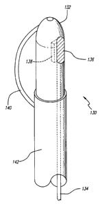
Referring now to FIG. 25, an alternate embodiment of a directional energy
applying
catheter is presented. In this embodiment, a catheter 130 having an optical
fiber diffusing tip
132 is used to directionally apply energy to a selected vascular segment. As
shown, an optical
fiber 134 is disposed within the catheter 130 and is connected at its distal
end to a light diffusing
device 136, such as a sapphire crystal, to allow diffusion of optical energy,
such as that
produced by a LASER connected to the proximal end of the catheter.
Additionally, the
diffusing tip may have a reflector 138 to direct the optical energy toward the
wall of the vein
and away from the catheter fumen in which the optical fiber is located. Other
light sources,
such as a flash lamp may be used. A tip deflecting wire or strut 140 is shown
in this
embodiment to be deployed for placing the optical energy radiating tip 132 in
apposition with
the vein wall, however, other devices may be used for accurate placement of
the energy source,
such as a balloon shown in FIG. 20. The outer sleeve 142 of the catheter is
slidable. Sliding
it toward the distal tip results in the strut 140 expanding and sliding the
sleeve in the proximal
direction results in the strut 140 contracting.
As can be readily ascertained from the disclosure herein, the surgical
procedure of the
present invention is accomplished without the need for prolonged
hospitalization or
post-operative recovery. The restoration of venous function is possible
without the need for
continued lifestyle changes, such as frequent leg elevation, the wearing of
elastic support
stockings, or prolonged treatment of recurrent venous stasis ulcers. Moreover,
the need for
surgery of the arin and leg for transplantation of arm veins into the leg
would not be necessary.
Early treatment of venous disease could prevent more serious complications
such as
ulceration, and valve damage caused by thrombophlebitis or thromboembolism.
The cost of
treatment and complications due to venous disease would be significantly
reduced. There would
be no need for extensive hospitalization for this procedure, and the need for
subsequent
treatment and hospitalization would also be reduced froin what is currently
needed.
Furthermore, the minimally invasive nature of the disclosed methods would
allow the medical
practitioner to repair or treat several vein sections in a single procedure in
a relatively short
period of time.
SUBSTITUTE SHEET (RULE 26)
r .t_ I
CA 02282546 1999-08-27
WO 98/38936 PCT/US98/02247
It is to be understood that the type and dimensions of the catheter and
electrodes may
be selected according to the size of the vein to be treated. Although the
present invention has
been described as treating venous insufficiency of the lower limb such as
varicose veins in the
leg, the present invention can be used to intraluminally treat venous
insufficiency in other areas
5 of the body. For example, hemorrhoids may be characterized as outpocketed
varicose veins
in the anal region. Traditional treatments include invasive surgery, elastic
ring ligation, and the
application of topical ointments. Shrinking the dilated veins using RF energy
can be
accomplished in accordance with the present invention. Specifically, the
catheter and electrode
combination is introduced into the venous system, into the external iliac
vein, the internal iliac
] 0 vein, then either the hemorrhoidal or the pudendal vein. The catheter then
delivers the
electrode to the site of' the dilated hemorrhoidal vein by this transvenous
approach.
Fluoroscopic techniques or any other suitable technique sucli as pulse-echo
ultrasound, as
previously discussed, can be used to properly position the electrode at the
venous treatment
site. The treatment site is preferably selected to be at least two centimeters
above the dentate
15 line to minimize pain. The electrode applies RF energy at a suitable
frequency to minimized
coagulation for a sufficient amount of time to shrink, stiffen, and fixate the
vein, yet maintain
venous function or valvular competency. This intraluminal approach avoids the
risks and
morbidity associated with more invasive surgical techniques such as
hemorrhoidectomy, while
significantly reducing reflux of blood in the area without necrosing or
removing the venous
20 tissue.
Anotlier area of venous insufliciency relates to erectile impotency of the
penis. A
significant number of all physically-induced cases of impotence result from
excessive drainage
of blood from the penile venous systeni Venous-drainage-impotence can be
treated using the
present invention. Catheters having a sufficiently small diameter can be used
to deliver the
25 electrodes through the dorsal vein of the penile venous system to shrink
this venous outflow
path. Fluoroscopic or ultrasound techniques can be used to properly position
the electrode
within the incompetent vein. RF energy or other radiant energy is applied from
the electrodes
at a suitable frequency to shrink the surrounding venous tissue in order to
reduce the excessive
amount of drainage from the penis while maintaining venous function or
valvular competency.
The amount of shrinkage of the vein can be limited by the diameter of the
catheter itself, or the
catheter or electrodes themselves can be expanded to the appropriate size.
Ligation of these
SUBSTITUTE SHEET (RULE 26)
CA 02282546 1999-08-27
WO 98/38936 PCT/US98/02247
26
veins should be avoided so as to allow for the proper drainage of blood from
an engorged penis
which is necessary for proper penile function.
Another area of venous insufficiency suitable for treatment in accordance with
the
present invention involves esophageal varices. Varicose veins called
esophageal varices can
form in the venous system along the submucosa of the lower esophagus, and
bleeding can occur
from the swollen veins. Properly sized catheters can be used in accordance
with the present
invention to deliver the electrodes to the site of venous insufl"iciency along
the esophageal
varices. Endovascular access for the catheter is preferably provided through
the superior
mesenteric vein or portal vein to shrink the portal vein branches leading to
the lower esophagus.
Proper positioning of the electrode within the vein can be confirmed using
fluoroscopic or
ultrasound techniques. The electrodes apply RF energy or- other radiant energy
at a suitable
frequency to shrink the vein arid reduce the swelling and transniission of
high portal venous
pressure to the veins surrounding the esophagus.
While several particular forms of the invention have been illustrated and
described, it
will be apparent that various modifications can be made without departing from
the spirit and
scope of the invention. Accordingly, it is not intended that the invention be
limited, except as
by the appended claims.
SUBSTITUTE SHEET (RULE 26)
r , ,