Note: Descriptions are shown in the official language in which they were submitted.
CA 02282559 1999-12-02
LOWER PRE-HEAT BLOCK FOR USE IN METAL SCARFING
APPARATUS
FIELD OF THE INVENTION
The invention relates in general to an apparatus used for the
thermochemical scarfing of metal workpieces. More particularly, the invention
relates to an improved lower pre-heat block assembly for use with such an
apparatus in which the block assembly is constructed and arranged to create a
sheet-like gas flow for shielding a separate sheet-like oxidizing gas flow
generated
during the scarfing process to attain a smooth scarfed surface on the metal
workpieces.
BACKGROUND OF THE INVENTION
In the production and finishing of metal workpieces, for example elongate
steel slabs, billets, and bar stock, the steel is conditioned or surface
finished by
creating relative motion between the steel workpiece and a scarfing apparatus
having at least one scarfing unit positioned along the top, bottom, or side
surfaces
of the workpiece to eliminate surface defects such as cracks, seams, slag
inclusions, surface oxides, and mechanical defects resulting from the rolling
or
casting process, for example. One known type of such a scarfing apparatus
includes top, bottom, and opposed side scarfing units that are mounted across
the
width and end portions of the workpiece to concurrently scarf each of the
sides of
the workpiece as it is passed through the scarfing apparatus and between the
scarfing units so provided.
The top, side, and bottom scarfing units of the scarfing apparatus each
include a manifold and head assembly constructed and arranged to receive and
distribute both oxygen and fuel gas to opposed upper and lower pre-heat blocks
or
block assemblies provided as a part of each such scarfing unit. The respective
upper and lower pre-heat blocks are spaced from one another to define an
oxygen
scarfing slot there between, and through which a quantity of oxygen is passed
under pressure and directed toward the workpiece to enable the thermochemical
scarfing process to occur. The lower pre-heat block will typically include a
fuel
-1-
CA 02282559 1999-12-02
gas channel having a discharge opening positioned adjacent the oxygen slot
formed
by the upper and lower pre-heat blocks for discharging a fuel gas adjacent the
oxygen flow for the purpose of maintaining the oxidation reaction on the
surface of
the workpiece, and for also shielding the oxygen flow from aspiration, i.e.,
from
mixing with ambient air, which tends to diminish the effectiveness of the
thermochemical scarfing process.
One example of such a known type of lower pre-heat block is disclosed in
U.S. Patent No. 2,838,431 to Allmang et al., in which the pre-heat block is
disclosed as being of one piece construction and includes a spaced series of
fuel
gas outlets extending across the width of the front face of the block. The
fuel gas
is delivered to the inlet ports through a number of laterally spaced fuel gas
lines
which extend from a rear face of the block to a transverse internal bore
positioned
just behind, and in communication with the inner ends of the outlet ports. An
elongate dividing rod, or bar, comprising a number of spaced transverse discs
is
positioned within the bore so as to divide the bore into a series of uniform
gas
distribution chambers. The ends of the bore are closed with end seals in known
fashion.
Although the fuel gas outlet ports defined in the front face of the lower pre-
heat block of Allmang, et al. were an improvement over the then-known scarfing
machines, in that the fuel gas ports were closely spaced with respect to one
another
in the effort to prevent outside air from aspirating with the oxidizing gas
stream,
the problem still remained that outside air would tend to be drawn toward and
between the fuel gas outlet ports such that outside air would aspirate with
the
oxidizing gas flow.
As known to those of skill in the art, the shielding of the sheet-like oxygen
stream, or oxidizing gas flow created when oxygen is passed between the upper
and lower pre-heat blocks is most critical in producing a smooth scarfed
surface on
the workpiece being scarfed as any variation or inconsistency in the lower pre-
heat
block fuel gas flame can cause a variation in the scarfed surface. Any such
variation can lead to non-uniform metal removal, with ridges and valleys being
the
result, such that the scarfing depth must be increased in order that these
ridges or
valleys be removed, i.e., a sufficient quantity of the surface of the object
must be
removed to provide for the removal of all such surface defects which pre-
existed
the scarfing process, as well as those which may have been caused by the
scarfing
-2-
CA 02282559 1999-12-02
process. As a result, the scarfing apparatus of Allmang, et al. and others
similarly
constructed, led to the removal of excess metal, causing otherwise
satisfactory
metal to be removed which increases Yield loss rates during the workpiece
finishing process.
The scarfing apparatus of Allmang et al. was improved upon in U.S. Patent
No. 3,231,431 to Allmang by adding an elongate baffle strip of an approximate
one-half inch ( 1 /2) length positioned approximately one-quarter ( 1 /4) inch
below
the oxygen slot to prevent the aspiration of ambient air into the oxygen
stream, as-
disclosed in Column 2, Lines 34-72, and Column 3, Lines 1-13 thereof. As
stated
in Column 2, Lines 61-65 ofAllmang, it was believed that a confining action
caused by the baffle strips on both sides of the oxygen-fuel mixture prevented
atmospheric air from aspirating with the oxygen at a point adjacent to each
row of
pre-heat (gas outlet) ports.
Although the patent to Allmang represented an improvement in the art, the
need still existed for an improved scarfing apparatus which would more
consistently produce a smooth surfaced scarfed metal workpiece. It was to the
attainment of this object that the lower pre-heat block assembly of Showalter,
et al.
disclosed in U.S. Patent No. 5,497,976 was developed. Showalter attained a
smooth surface scarf by providing a lower pre-heat block assembly for use in a
thermochemical scarfing apparatus which included an improved fuel gas delivery
system for delivering a stream of fuel gas uniformly across the full width of
the
metal workpiece, and which shielded the oxidizing gas flow to ensure that the
peaks and valleys resulting from the use of the earlier known scarfing devices
were
minimized. This was accomplished by providing a two-piece lower preheat block
assembly having a base member or block, and an extension releasedly fastened
thereto in engaging and overlying relationship on the front face of the block.
An
elongate gas discharge slot was machined into the extension, which slot
communicated with a spaced series of gas discharge ports defined within and
extending longitudinally across the front face of the block. The extension
also
included internal baffles for inducing turbulence in the fuel gas flow to
ensure
complete mixing of the fuel gas, such that the fuel gas would be emitted
through
the gas discharge slot as a uniform flow across the face of the extension.
The lower pre-heat block assembly of Showalter et al. represented a
significant advance in the art, but it required that a two-piece lower pre-
heat block
-3-
CA 02282559 1999-12-02
assembly be manufactured in which a precisely machined slot is required within
the extension, and which also required the use of internal baffles for
inducing
turbulence in the fuel gas flow to ensure that the fuel gas is distributed
uniformly
across the width of the extension in order to prevent ambient air from
aspirating
with the oxidizing/oxygen gas flow as it is passed between the upper and lower
pre-heat block assemblies, and directed toward the metal object or workpiece
to be
thermochemically scarfed.
What is needed, therefore, but seemingly unavailable in the art is an
improved lower pre-heat block assembly for use with a thermochemical scarfing,
apparatus which is simple in 'design and manufacture, and which will ensure
that a
sheet-like fuel gas flow is produced for shielding the oxidizing gas flow.
In the lower pre-heat block assembly of Showalter et al., the disclosed gas
discharge slot is provided within an otherwise conventional extension having a
baffle similar to that disclosed in U.S. Patent No. 3,231,431 to Allmang, such
that
should the fuel gas discharge slot became plugged or obstructed at any point
along
its length, the probability exists that ambient air will be allowed to
aspirate with the
oxidizing gas flow, which may lead to the formation of peaks and valleys
during
the metal scarfing process. What is needed, therefore, is an improved lower
pre-
heat block assembly for use with a scarfing apparatus in which a gas discharge
outlet which is less likely to become obstructed is defined within the modular
base
or block, and with which the extension can be placed in engaging and overlying
position such that it defines a gas discharge orifice of a desired size in the
face of
the block for simplifying the manufacture of the lower pre-heat block
assembly,
and for allowing the fuel gas to be distributed evenly across the width of the
lower
block assembly so that the lower block will perform satisfactorily even if
there
may be plugs or obstructions in the gas discharge outlets to shield the
oxidizing gas
flow from ambient air during the scarfing process.
Lastly, although the baffle of the patent to Allmang proved useful in
minimizing the aspiration of ambient air within the oxidizing gas flow, this
problem still persists, even with the improved lower pre-heat block assembly
of
Showalter et al. Accordingly, what is needed is an improved lower pre-heat
block
assembly for use with a thermochemical scarfing apparatus which is constructed
to
utilize the oxidizing gas flow as it is passed over the lower pre-heat block
assembly
to pneumatically compress, or squeeze, the fuel gas between the oxidizing gas
flow
-4-
CA 02282559 1999-12-02
and the lower pre-heat block assembly such that the fuel gas is uniformly
distributed across the width of the lower pre -heat block assembly, and for
forming
a sheet-like fuel gas flow which shields and adjoins the oxidizing gas flow as
it is
continues on toward the metal workpiece to be scarfed so as to minimize the
likelihood that peaks and valleys will be formed during the scarfing process,
and to
improve production yields during the metal finishing process.
SUMMARY OF THE INVENTION
The present invention provides an improved lower pre-heat block assembly
for use with a thermochemical scarfing machine which overcomes some of the
design deficiencies of the other lower pre-heat block assemblies known in the
art.
The lower pre-heat block assembly of this invention provides a simple,
efficient,
and highly flexible apparatus for uniformly distributing a fuel gas across the
width
of a lower pre-heat block assembly, and for forming the fuel gas into a sheet-
like
fuel gas flow which adjoins and shields an oxidizing gas flow passed over the
lower pre-heat block assembly and along a flow path leading toward a metal
object, or workpiece, to be thermochemically scarfed during the steel
finishing
process. The relative simplicity of this improved lower block assembly in
comparison with the known lower block assemblies allows for a greater degree
of
reliability in shielding the oxidizing gas flow, and in maintaining its sheet-
like flow
characteristics along the flow path to minimize the formation of peaks and
valleys
in the surface of the metal workpieces being thermochemically scarfed with the
scarfing apparatus.
This invention attains this high degree of flexibility, maintainability,
reliability, as well as simplicity in design and operation, by providing a
lower pre-
heat block assembly for use with the thermochemical scarfing apparatus
comprising a modular block having opposed upper and lower faces, opposed end
faces, and opposed front and rear faces extending between the end of faces in
a
longitudinal direction. A gas discharge outlet is defined within, and extends
longitudinally across the front face of the block. A modular extension is
engaged
on, and partially overlies the front face of the block. The extension may
partially
overlie the gas discharge outlet to define a gas discharge orifice in
communication
with the gas discharge outlet on the front face of the block, as desired. The
-5-
CA 02282559 1999-12-02
extension is constructed and arranged to be releasably secured to the front
face of
the block. A feature of this construction is that the lower pre-heat block
assembly
of this invention does not therefore require the fabrication of a precisely
machined
fuel gas discharge slot or orifice therein and is less susceptible to dirt or
other
obstructions fouling the gas discharge outlet, which may in turn prevent the
distribution of the fuel gas uniformly across the lower block assembly. This
therefore minimizes the likelihood of disruptions in the oxidizing gas flow,
and
allows for a lower pre-heat block assembly which is simple to manufacture, and
provides greater production efficiencies when in use.
The extension has a separate upper face and an opposed lower face,
opposed end faces, and opposed front and rear faces extending between the end
faces in a longitudinal direction. The rear face of the extension is placed in
an
overlying relationship on the front face of the block. The upper face of the
extension is recessed with respect to, i. e. it is positioned below, the level
of the
upper face of the block such that the extension is stepped down a pre-
determined
height from the upper face of the block. The extension further comprises a
leading
edge spaced from the front face of the block which extends longitudinally
along
the length of the extension. The leading edge of the extension may be recessed
with respect to the front face of the extension for forming a notch to
protect, or
shield, the leading edge with the front face-of the extension.
The lower, pre-heat block assembly of this invention is intended for use in
a conventional thermochemical scarfing apparatus in which an upper pre-heat
block assembly is provided, the lower pre-heat block assembly being spaced
from
and opposed to the upper block assembly such that an oxygen slot is defined by
and between the two block assemblies, and through which oxygen is passed and
formed into an oxidizing gas flow moving along a flow path extending toward
the
metal workpiece to be scarfed: In fashion heretofore unknown in the art, the
unique construction of the lower pre-heat block assembly of this invention
makes
use of the expansion of the oxidizing gas flow to "pneumatically" compress or
squeeze the fuel gas between the oxidizing gas flow, the front face of the
modular
block, and the second upper face provided on the extension along the
longitudinal
length of the lower pre-heat block assembly, i.e., across the width of the
workpiece
being scarfed, to ensure that the fuel gas is uniformly distributed along
substantially the full longitudinal extent of the front face of the lower pre-
heat
-6-
CA 02282559 1999-12-02
block assembly, and to pass the compressed and now distributed fuel gas as a
substantially uniform and sheet-like gas flow through a pneumatic slot formed
by
and between the oxidizing gas flow and the leading edge of the extension to
ensure
that the sheet-like fuel gas flow underlies and adjoins the sheet-like
oxidizing gas
flow as they then both flow together along the flow path toward the metal
workpiece to be scarfed. The unique construction of this lower pre-heat block
assembly thus provides for the uniform distribution of fuel gas across the
width of
the oxidizing gas flow to greatly minimize the likelihood of ambient air
aspirating
with the oxidizing gas flow, and is constructed to keep a smooth sheet-like
oxidizing gas flow moving toward the workpiece so that a more smoothly scarfed
surface of the workpiece results, thus resulting in greater production yields
and
manufacturing efficiencies than the known scarfing devices.
The improved lower pre-heat block assembly of this invention, therefore,
also results in a new method of shielding the oxidizing gas flow of a
thermochemical scarfing machine during use, which method comprises the steps
of
passing the sheet-like oxidizing gas flow over the upper surface of the
modular
base or block of the lower pre-heat block assembly; discharging a fuel gas
from a
fuel gas discharge outlet defined in the front face of the block adjoining a
first
upper face thereof so as to form a sheet-like fuel gas flow which underlies
the
oxidizing gas flow; compressing the sheet-like fuel gas flow between the front
face
and a second upper face formed on the extension of the lower pre-heat block
assembly with the oxidizing gas flow so that the sheet-like fuel gas flow is
substantially and uniformly distributed under the sheet-like oxidizing gas
flow,
whereupon both of the sheet-like gas flows pass together along the flow path
toward the workpiece to be scarfed, the sheet-like gas flow shielding the
sheet-like
oxidizing gas flow from ambient air to permit the scarfing of a smooth surface
on
the metal workpiece without the peaks and valleys caused by ambient air being
allowed to aspirate with the oxidizing gas flow.
The step of forming the fuel gas into the sheet-like fuel gas flow also
includes the step of pneumatically squeezing the fuel gas against the front
face of
the block, the upper face of the extension, and the oxidizing gas flow, and
passing
the fuel gas through a pneumatic slot defined by the oxidizing gas flow and a
leading edge extending the longitudinal length of the upper face of the
extension to
form the fuel gas into the sheet-like fuel gas flow adjoining the oxidizing
gas flow.
CA 02282559 2003-10-O1
It is, therefore, an object of an aspect of the present invention to provide
an
improved lower pre-heat block assembly for use in a metal scarfing apparatus
which
will reliably and consistently produce a smooth scarfed surface on a metal
workpiece
being thermochemically scarfed therewith.
It is another object of an aspect of the present invention to provide an
improved lower pre-heat block assembly for use in a metal scarfing apparatus
which
is simple in design and construction, is rugged and durable in use, and is
easy to use
and maintain. Yet another object of an aspect of the present invention is to
provide an
improved lower pre-heat block assembly for use in a metal scarfing apparatus
which
will minimize the likelihood of ambient air aspirating with the oxidizing gas
flow, and
for forming a sheet-like fuel gas flow adjoining the oxidizing gas flow to
shield the
oxidizing gas flow during the thermochemical scarfing process.
According to an aspect of the present invention, there is provided an
assembly for use in a thermochemical scarfing apparatus and comprises:
a block having opposite upper and lower faces, opposite end faces, and
opposite front and rear faces extending between said end faces to define a
longitudinal
direction extending there between,
an extension extending in a forward direction from said front face of
said block and including a second upper face which is parallel to said upper
face of
said block, and with said second upper face being spaced below said upper face
of
said block so as to define a pre-determined height, and wherein the second
face
extends forwardly from said front face a distance ofbetween about 2'/2 to 5
times said
pre-determined height, and
gas discharge outlet means positioned to communicate with said front
face between said upper face of said block and said second upper face and
extending
longitudinally across substantially the full longitudinal extent of the front
face, such
that a gas may be discharged forwardly from said outlet means to form a sheet-
like
gas flow extending forwardly across said second upper face.
According to another aspect of the present invention, there is provided
a thermochemical scarfing apparatus which comprise:
an upper block having a lower face,
a lower block having opposite upper and lower faces, opposite end
faces, and opposite front and rear faces extending between said end faces to
define a
_8_
CA 02282559 2003-10-O1
longitudinal direction extending there between, said lower block being
positioned
below said upper block so that the lower face of said upper block and said
upper face
of said lower block define an elongate slot through which a first gas may be
discharged in the form of a sheet-like gas flow which moves forwardly toward a
metal
workpiece to be scarfed,
an extension extending in a forward direction from said front face of
said block and including a second upper face which is parallel to said upper
face of
said block, said second upper face being spaced below said upper face of said
lower
block, and
gas discharge outlet means positioned to communicate with said front
face of said lower block and between said upper face of said lower block and
said
second upper face of said extension, and said outlet means extending
longitudinally
across substantially the full longitudinal extent of the front face, such that
a second gas
may be discharged forwardly from said outlet means to form a second sheet-like
gas
~ 5 flow moving forwardly across said second upper face, and such that a
pneumatic slot is
defined between said first sheet-like gas flow and said second upper face of
said
extension which serves to compress the second sheet-like gas flow as it moves
forwardly
across the second upper face of the extension.
According to a further aspect of the present invention, there is
provided a method of shielding an oxidizing gas flow during a thermochemical
scarfing procedure the method comprising the steps of:
passing a sheet-like oxidizing gas flow across a first upper face of a
block assembly, while
discharging a fuel gas from a fuel gas outlet positioned in a front face
of the block assembly adjoining said upper face and so as to form a second
sheet-like
fuel gas flow which underlies said sheet-like oxidizing gas flow, while
compressing the second sheet-like fuel gas flow between a second
upper face which extends forwardly from said front face and the sheet-like
oxidizing
gas flow to thereby substantially uniformly distribute the second sheet-like
fuel gas
flow under the sheet-like oxidizing gas flow
forming a pneumatic slot between said sheet-like oxidizing gas flow
and said second upper face, said slot extending longitudinally across
substantially the
full longitudinal extent of said second upper face, the fuel gas being
compressed as it
-8a-
CA 02282559 2003-10-O1
passes through said slot to form said second sheet-like fuel gas flow.
It is to these objects, as well as the other objects, features, and
advantages of the present invention, which will become apparent upon reading
the
specification, when taken in conjunction with the accompanying drawings, to
which
the invention is directed.
BRIEF DES~IP_~'IQN OF THE DRA I'N NGS
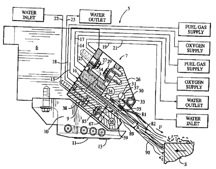
FIG. 1 is a partially sectioned, schematic side elevational view of a scarfing
apparatus in which the improved lower pre-heat block of the present invention
is
positioned for pre-heating a steel slab before the commencement of a
thermochemical
scarfing operation;
FIG. 2 is an exploded front perspective view of a first embodiment of the
lower pre-heat block of the invention.
FIG. 3 is a partial cross-sectioned side elevational view of the embodiment of
the lower pre-heat block of FIG. 2, in which a notch is defined along the
leading edge
of the extension thereof
FIG. 4 is an exploded perspective view of a second embodiment of the lower
pre-heat block of the invention.
FIG. 5 is a partial cross-sectioned side elevational view of the lower pre-
heat
block of FIG. 4, in which a notch is defined along the leading edge of the
extension
thereof
FIG. 6 is a partial front elevational view of the pre-heat block of FIG. 4.
-8b-
CA 02282559 1999-12-02
FIG. 7 is an exploded perspective view of a third embodiment of the lower
pre-heat block of the invention.
FIG. 8 is a partial cross-sectioned side elevational view of the lower pre-
heat block of FIG. 7, in which a notch is defined in the leading edge of the
extension thereof.
FIG. 9 is a perspective view of a fourth embodiment of the lower pre-heat
block of the invention, in which the block is manufactured as a one-piece
unit.
FIG. 10 is a partial cross-sectioned side elevational view of the lower pre-
heat block of FIG. 9:
FIG. 11 is a partial schematic illustration of the lower pre-heat block of
FIGS. 2-6 in use with a thermochemical scarfing apparatus, illustrating the
formation of the pneumatic slot ~y the oxidizing gas flow as it is passed over
the
lower pre-heat block, and of the sheet-like fuel gas flow formed thereby which
underlies and adjoins the oxidizing gas flow as it moves along a flow path
leading
toward the metal workpiece to be scarfed.
DETAILED DESCRIPTION OF THE PREFERRED EMBODIMENTS
Referring now in detail to the drawings, in which like reference characters
indicate like parts throughout the several views, a thermochemical scarfing
apparatus 5 is illustrated in FIG. 1. Scarfing apparatus 5 includes a manifold
and
head assembly 6 constructed in known fashion, the manifold and head assembly
being constructed and arranged to receive and mount an upper pre-heat block
assembly 7, and a spaced, opposed lower pre-heat block assembly 9. The
scarfing
apparatus also includes, in known fashion, a riding shoe 10 fastened to the
manifold and head assembly, the riding show having a lower surface 11 on which
at least one skid 13 is formed. The riding shoe and skids are provided such
that as
a metal workpiece, for example a steel stab, denoted by reference character
"S" in
FIG. l, is advanced along a path of travel past the scarfing apparatus, the
manifold
and head assembly can be moved into position such that the skids 13 of the
riding
shoe engage and ride upon a respective one of the upper, lower, or side
surfaces of
the steel slab, respectively, each of which will be provided with a separate
scarfing
apparatus constructed in a fashion similar, if not identical, to the
construction of
scarfing apparatus 5 of FIG. 1. Scarfing apparatus 5 as shown in FIG. 1 is an
-9-
CA 02282559 2003-10-O1
upper scarfing apparatus with respect to the steel slab as it is advanced
along the path
of travel thereby. The construction of scarfing apparatus 5, and more
particularly the
construction of manifold and head assembly 6 is described in greater detail in
U.S.
Patent No. 5,234,658 issued to Showalter et al.
So constructed, manifold and head assembly 6 includes a first oxygen line 14
through which pressurized oxygen, used as the oxidizing gas in the
thermochemical
scarfing operation, supplied from an oxygen supply source schematically
illustrated in
FIG. 1, is passed to upper pre-heat block assembly 7. A second oxygen supply
line 15
supplies oxygen to an oxygen slot 16 formed by and between the two upper and
lower
pre-heat block assemblies, respectively, such that the oxygen is formed into a
sheet-
like oxidizing gas flow 82 (FIGS. 1 and 11) as it is passed between the two
pre-heat
block assemblies, and extends along a flow path, as noted by reference
character "F"
in FIG. 1, leading toward the steel slab or other metal workpiece to be
scarfed. The
manifold and head assembly also includes a water supply line 19, which is
supplied
with water from a schematically illustrated water supply source, to upper pre-
heat
block assembly 7, and a water return line 21 such that cooling water may be
circulated
through the upper pre-heat block assembly in known fashion. In similar
fashion,
manifold and head assembly 6 also includes a second water supply line 22 which
provides cooling water to the lower pre-heat block assembly 9, with a second
water
return line 23 such that the cooling water may be circulated through the lower
pre-
heat block assembly in known fashion.
The upper pre-heat block assembly 7 is best illustrated in FIG. 1, and is
shown
to have a modular base member or upper block 25, with an upper extension 26
engaged thereon in overlying relationship. Block 25 is secured to a mounting
face
(not illustrated) defined on the manifold and head assembly by a suitable
fastener 27,
whereas upper extension 26 is fastened to upper block 25 by a suitable
fastener 29.
Fasteners 27 and 29 may comprise, for example, threaded bolts, or machine
screws.
An internal water passageway 30 is defined within upper extension 26, in
known fashion, in communication with water supply line 19, and water discharge
line
21 such that cooling water can be circulated therethrough. A first internal
oxygen
passageway 31, or manifold, is defined within the upper extension, and
-10-
CA 02282559 2003-10-O1
extends in the longitudinal or lengthwise direction of the upper extension for
supplying oxygen to an oxygen discharge outlet 33, or discharge orifice,
defined
within upper extension 26. Although only one oxygen discharge outlet 33 is
shown in
FIG. 1, it is anticipated that a spaced series of such discharge outlets will
be defined
along the length of the upper extension in fashion described in greater detail
in U.S.
Patent Nos. 5,358,221 and 5,472,175 to Showalter et al. Oxygen passageway 31
is in
communication with oxygen supply line 14.
Still referring to FIG. l, upper extension 26 includes a second oxygen
passageway 34, or manifold, defined therein and extending longitudinally along
the
length of the extension with respect to the width of the steel slab advancing
along the
path of travel toward, and past, the scarfing apparatus such that in this
instance, the
steel slab is scarfed across its entire upper surface by scarfing apparatus 5.
Oxygen
passageway 34 is also in communication with oxygen supply line 14, and is
positioned at the distal end of a fuel gas/oxygen nozzle assembly 35
positioned
within, and provided as a part of upper extension 26. Nozzle assembly 35 is
described in greater detail in the two aforementioned patents to Showalter, et
al. as
well as in U.S. Patent No. 5,333,841, to Showalter et al. Accordingly, upper .
extension 26 thus includes an internal fuel gas passageway 37, or manifold,
extending
longitudinally along the length of the upper extension, and being in
communication
with nozzle assembly 35 intermediate its proximal and distal ends. The
proximal end
of nozzle 35 is positioned flush with the front face of upper extension 26,
such that a
central oxygen, or oxidizing gas flow is emitted therefrom with a surrounding
fuel gas
flow for shielding the oxidizing gas flow.
Upper block 25 and upper extension 26 will each be fashioned from a suitable
and durable metallic material, such as a bronze or copper material, and more
preferably of copper.
A first embodiment of lower pre-heat block assembly 9 is illustrated in FIGS.
1-3, in which the lower pre-heat block assembly comprises a lower modular base
member or lower block 38, and a modular lower extension 39 which is engaged
upon,
and at least partially overlies lower block 38. Lower block 38 is releasably
secured to
manifold and head assembly 6 by a suitable fastener or fasteners (not
illustrated), and
lower extension 39 may be releasably secured to
-11-
CA 02282559 2003-10-O1
lower block 38 if so desired (FIGS, 2-5) or, in the alternative the lower
extension may
be formed as a part of the lower block such that lower block and extension
comprise a
single metallic block as shown in FIGS. 9 and 10. Lower block 38 and lower
extension 39 are each fashioned of a suitable and durable metallic material,
for
example copper or bronze, and preferably of copper.
Referring now to FIGS. 2 and 3, a first two-piece embodiment of lower pre-
heat block assembly 9 is illustrated. Lower block 38 includes a planar upper
face 41,
an opposed lower face 42, opposed end faces 43 and 45, which adjoin the upper
and
lower faces along their common edges, with a front face 46 and an opposed rear
face
47 extending longitudinally in a length-wise direction of the lower pre-heat
block 38
between end faces 43 and 45. A water infeed passageway 49 is defined within
block
38, and extends from rear face 47 toward and through front face 46. Water
infeed
passageway 49 will be in communication with water supply line 22 illustrated
in
FIG. 1. In known fashion, and as disclosed in U.S. Patent No. 5,497,976, to
Showalter, et al., a concentric annular groove 50 lies about the opening of
water
infeed passageway 49, defined in front face 46 of the lower pre-heat block,
for a
receiving a suitable O-ring 53 (FIG. 3) for the purpose of sealing the water
infeed
passageway on extension 39. A water return passageway 51 is also defined
within
lower block 38, and extends from the front face 46 toward and through rear
face 47,
and is in communication with water discharge line 23 of FIG. 1. As with the
water
infeed passageway 49 defined in the lower block, an annular groove 52
circumscribes
the opening formed in front face 46 by water return passageway 51 far
receiving an
O-ring 53 (FIG. 3) therein to seal the passageway 39 between the block and the
extension.
As best shown in FIG. 1, and as disclosed in greater detail in U.S. Patent No.
5,497,976 to Showalter et al., a spaced series of gas supply ducts 54, only
one of
which is shown in FIG. l, extend from the rear face 47 toward, and in
communication
with a bore 55 which serves as a gas manifold, defined longitudinally within
lower
block 38. Each of the respective ones of gas supply ducts 54 is in
communication
with fuel gas supply line 18 illustrated in FIG. l, or its suitable
equivalent. Although
not illustrated in detail, an elongate rod 55' with a series of transverse
annular disks
spaced along its length is passed within the bore for forming a suitable
number of fuel
gas supply chambers within the bore
-12-
CA 02282559 2003-10-O1
such that the fuel gas will be turbulently mixed and passed as a substantially
uniform
flow through a gas discharge outlet 56. The construction of such an elongate
rod and
spacer disk device is described in U.S. Patent No. 2,838,431 to Allmang.
Refernng now to FIG. 2, the gas discharge outlet here is defined as an
elongate slot-
s like gas discharge outlet 56 extending longitudinally within the front face
46 of lower
pre-heat block 38, and which extends inwardly of the block such that it is in
communication with bore 55 for being supplied with fuel gas therefrom.
Lower pre-heat block assembly 9 of FIG. 2 also includes a separate lower
extension 39 which is constructed and arranged to be releasably secured to the
front
face of the lower block in engaging and partially overlying relationship.
Lower
extension 39 has a generally planar upper face 58 with an opposed lower face
59, a
pair of spaced end faces 60 and 62 adjoining the upper and lower faces of the
extension along their common edges, with a front face 63 and an opposed rear
face 64
extending in the longitudinal length-wise direction of the extension, and
joined to the
upper, lower, and end faces thereof along their common edges. As best shown in
FIGS. 1 and 3, an elongate bore or water passageway 66 is defined within the
extension along its longitudinal direction, and is in communication with a
water
supply duct 67 at each of its ends, there being two such spaced water supply
ducts
defined within the extension, one each of the water supply ducts being in
communication with either of water infeed passageway 49, or water discharge
passageway 51, respectively, defined within lower block 38.
In the two-piece configuration of lower block assembly 9 shown in FIGS. 1-8
and 11, lower extension 39 is fastened to lower block 38 by passing a threaded
fastener (not illustrated) through one of three spaced openings (not
illustrated) defined
in the rear face 47 of the lower block and extending longitudinally
therethrough and
through one of the three spaced openings 68 defined in front face 46 thereof,
and into
a respective one of three spaced threaded openings (not illustrated).defined
within the
rear face 63 of the lower extension, in known fashion, such that the lower
extension is
releasably secured to the front face of the lower block. Lower extension 39
also
includes, in known fashion, at least one, and in this instance two, dowel pins
(not
illustrated) spaced from one another, each of which extends laterally away
from the
rear face 64 of the extension and is sized and shaped to be received within a
respective one of the bores 69 defined within
-13-
CA 02282559 1999-12-02
the front face of the lower block, for guiding and aligning the lower
extension on
the lower block.
As shown in FIGS. 1 and 3, and in fashion heretofore unknown in the art,
in its two-piece configuration the block 38 and extension 39 are constructed
such
that as the extension is releasably secured to the block, the upper face 58
thereof
will intersect the gas discharge outlet 56 defined within the front face of
the block
such that the extension will define a gas discharge orifice 70 in
communication
with gas discharge outlet 56. An advantage of this construction is that gas
discharge outlet 56, here a slot, can be milled of a larger size with greater
ease, and
at lower cost, during fabrication of the block, rather than milling a precise
slot such
as that shown in the extension of the lower pre-heat block assembly of
Showalter
et al., U.S. Patent No. 5,497,976.
As known to those skilled in the art, a fuel gas is emitted through the lower
pre-heat block assembly 9 for the purpose of shielding the sheet-like
oxidizing gas
flow 82 (FIGS. 1, 11) which is generated by passing oxygen through the slot 16
defined by and between the upper and lower pre-heat block assemblies. If
ambient
air is allowed to aspirate, i. e. mix with and create turbulence within the
oxidizing
gas flow, the likelihood of undesirable peaks and valleys being scarfed in the
surface of the metal workpiece occurs, such that a greater quantity of the
exterior
surface of the metal workpiece must be scarfed to attain a smooth scarfed
surface,
which has the undesirable effect of lowering production yields. In the
scarfing
apparatus of U.S. Patent No. 5,497,976 to, Showalter et al, the lower pre-heat
block assembly is constructed and arranged such that a substantially uniform
flow
of the fuel gas along the longitudinal length, i.e. width of the object to be
scarfed,
is attained for shielding the oxidizing gas flow, and for minimizing the
prospect of
peaks and valleys being formed in the surface thereof to attain a smooth
scarfed
surface.
This requires, however, the precise machining of the slot within the
extension of the lower pre-heat block assembly of Showalter et al., as well as
the
machining of internal baffles within the extension, and/or the lower block of
the
pre-heat block assembly to ensure turbulent mixing of the fuel gas, such that
the
fuel gas flow is uniformly distributed along the length of the extension for
shielding the oxidizing gas flow from ambient air. If any openings are allowed
to
occur within the shielding fuel gas, for example should a portion of the slot
- 14-
CA 02282559 1999-12-02
become obscured or otherwise blocked, the likelihood of there being "breaks"
in
the shield which allow ambient air to aspirate with the oxidizing gas flow
increases. Although this device of Showalter et al., has proven to be a
significant
improvement in the art, the invention disclosed herein eliminates the need to
precisely machine a slot within the extension, rather a larger slot is
machined or
otherwise formed within the front face of the lower block 38, and extension 39
is
used to define an orifice in the front face of the block such that the pre-
heat block
assembly should be easier to manufacture, and should be easier to maintain
should
the extension become damaged during scarfing operation, for example should
molten metal strike and otherwise damage the extension, whereupon the
extension
can be quickly and easily replaced at minimal cost, rather than replacing a
precision machined extension.
As shown in FIG. 3, the rear face 64 of extension 39 is engaged on the front
face 46 of lower pre-heat block 38 such that the respective water supply ducts
at 67
are in alignment with the respective ones of the water passageways 49 and 51
defined within the lower pre-heat block, and so that the O-rings 53 positioned
within their respective grooves 51, 52 are compressed for sealing the water
supply
ducts on the rear face of the extension. As this occurs, and as described
above, the
upper face 58 of the extension forms the gas discharge orifice 70 of the lower
pre-
heat block 38.
In FIG. 2, a leading edge 71 is illustrated which extends along the length of
lower extension 39 where upper face 58 and front face 63 join one another.
However, as lower pre-heat block assembly 9 will be positioned closer to the
metal
workpiece to, be scarfed than will be the upper pre-heat block assembly, it is
desirable to protect the leading edge of the extension, for purposes which
will be
described in greater detail below. Accordingly, and as shown in FIG. 3, an
elongate notch 72 extending the length of lower extension 39 may be defined
therewithin for the purpose of recessing the leading edge 71 with respect to
the
front face 63 of the extension so that the front face of the extension is used
to
shield or protect the leading edge from damage. Again, and as described above,
a
feature of the two-piece construction of lower pre-heat block assembly 9 is
that
should extension 39 become damaged during the scarfing process, it can be
quickly
and easily removed and replaced on lower block 38.
-15-
CA 02282559 1999-12-02
A second embodiment of lower pre-heat block assembly 9 is illustrated in
FIGS. 4 through 6. Lower pre-heat block 38 of FIG. 4 is constructed in fashion
identical to lower pre-heat block 38 of FIG. 2, with the exception that rather
than
providing an elongate continuous slot as gas discharge outlet 56 (FIG. 1 ), a
spaced
and aligned series of circular openings 56' are defined within the front face
of
lower pre-heat block 38, as gas discharge outlets; each of which extends
inwardly
of the block and into communication with bore 55, also defined therein. Lower
extension 39 of FIG. 4 is constructed in fashion identical to lower extension
39 of
FIG. 2, and thus is not described in greater detail.
As with the embodiment of lower pre-heat block assembly 9 illustrated in
FIGS. 2 and 3, the lower pre-heat block assembly of FIGS. 4 through 6 is a two-
piece assembly in which extension 39 is releaseably secured to, and partially
overlies the front face of the lower block 38. Referring to FIG. 5, therefore,
extension 39 in this second embodiment of the lower pre-heat block assembly
defines a gas discharge orifice 70, or in this instance a spaced series of gas
discharge orifices 70 (FIG. 6) extending longitudinally across the front face
46 of
the lower pre-heat block. Again, a feature of this construction is that it is
relatively
simple and quick to drill a one-eighth inch hole, for example, within the
front face
of lower block 38, and then size the gas discharge orifices 70, as desired,
based
upon the length of rear face of 64 of extension 39 overlying the front face 46
of
block 38. As shown in FIG. 6, therefore, the result of extension 39 being
engaged
upon and partially overlying the front face and gas discharge outlets 56' is
that a
spaced series of semi-circular openings are defined by the extension, each of
which
serves as a gas discharge orifice 70. Also, and as shown in FIG. S, an
elongate
notch 72 may be defined within, and extending along the length of the leading
edge
71 of the upper face of the extension such that the leading edge, and the
upper face,
respectively, are shielded by front face 63 of the assembly during the
scarfing
process.
A third embodiment of lower pre-heat block assembly 9 is illustrated in
FIGS. 7 and 8. Once again, lower block 38 is constructed in fashion identical
to
lower blocks 38 of FIGS. 2 and 4, with the exception that each one of the
circular
openings 56' defined in front face 46 of lower block 38 includes an insert 57,
preferably a machined copper insert, fashioned to be fit as a sleeve within
the
respective ones of the circular openings 56', and having an internal
passageway
- 16-
CA 02282559 2003-10-O1
defined therein as gas discharge orifice 70, and extending therethrough in
communication with bore 55 defined in lower block 38. In this embodiment of
the
lower pre-heat block assembly, however, it is shown in FIG. 8 that although
extension
39 is releasably secured to the lower block 38, the extension here does not
partially
overlie and define a gas discharge orifice within the front face of the lower
block,
rather the gas discharge orifice 70 is defined by the central passageway or
bore
defined within and extending through each one of inserts 57.
It is a feature of the construction of lower pre-heat block assembly 9 of
FIGS. 7 and 8, therefore, that the circular openings 56' defined within the
front face of
the lower block can be oversized with respect to those machined within the
lower
block 38 of FIG. 4, such openings being relatively quick and easy to form,
whereupon
an insert having a precisely drilled passageway, for example a passage being
one-
tenth of an inch or nine-hundredths of a inch in diameter and extending
theretbrough,
is provided for emitting the fuel gas therethrough during the scarfing
process.
However, and if so desired, it is anticipated that lower extension 39 could
partially
overlie the inserts 57 and could form the gas discharge orifice 70 defined by
the
drilled holes within each respective one of the inserts.
As shown in FIG. 8, the lower extension 39 has a leading edge 71 extending
along its length where upper face 58 and front face 63 join one another, and
may also
be provided with a notch 72 for recessing the leading edge with respect to
front face
63 of the extension for the purpose of shielding and/or protecting the leading
edge
from damage during this the scarfing process for reasons described in great
detail
below.
A fourth embodiment of lower pre-heat block assembly 9 is illustrated in
FIGS. 9 and 10, in which a modular one-piece pre-heat block assembly is
provided.
The lower pre-heat block assembly 9 of FIG. 9 thus includes a lower block 38'
having
a substantially planar upper face 41, an opposed lower face 42, a pair of
spaced and
opposed end spaces 43 and 45 extending along the common edges of the upper and
lower faces, a rear face 47 extending in the longitudinal direction of the
block from
end face 43 to end face 45 and being joined to the upper and lower faces
thereof along
their common edges, and an integral lower extension 39' formed as part of
block 38'.
Extension 39' has an upper face 58 which is recessed a pre-determined height
from,
and with respect to, upper face 41 of block 38'. Upper face 58 also lies
substantially
parallel to upper face'41.
-17-
CA 02282559 1999-12-02
Extension 39' has a lower face 59 opposed to and spaced from upper face 58,
and a
pair of opposed and spaced end faces 60 and 62. Extension 39' also includes a
front face 63 extending in the longitudinal/lengthwise direction thereof,
between
end faces 60 and 62, and adjoining upper face 58 along a leading edge 71
extending the length of the extension.
As with the embodiment of the lower pre-heat block assembly illustrated in
FIGS. 7 and 8, block 38' is provided with an aligned and spaced series of
openings
56' defined within front face 46 thereof and extending inwardly of the block
into
communication with bore 55. Each one of the openings 56' has a respective one
of
the inserts 57, described in greater detail above, received therein, such that
the
inserts define the respective ones of the gas discharge orifices 70 across the
front
face of lower block 38'.
As best shown in FIG. 10, in this embodiment of the lower pre-heat block
assembly a bore 66 is once again defined within the extension 39' so that
cooling
water may be circulated therethrough, the bore having a water supply duct 6T
formed at its respective ends adjacent end faces 43, 45, 60, and 62,
respectively,
extending toward and opening onto the rear face 47 of the block 38', one each
of
the two respective water supply ducts 67' being in communication with either
water supply line 22 (FIG. 1 ) or water discharge line 23 (FIG. 1 ),
respectively.
In both the two piece embodiments of lower pre-heat block assembly 9
illustrated in FIGS. 1 through 8, and in the one-piece embodiment illustrated
in
FIGS. 9 & 10, lower blocks 38, 38', and lower extensions 39, 39' will each be
comprised of a metallic material, preferable bronze or copper, and more
preferably
of copper. Also, although an elongate slot 56 is shown as the gas discharge
outlet
in the embodiment of the invention shown in FIG. 2, a spaced series of
circular
openings 56 are shown as the gas discharge outlets in the embodiment of the
invention illustrated in FIG. 4, and a spaced series of openings 56' with a
respective one of the inserts 57 provided therein form the gas discharge
outlets and
orifices in the embodiments of the invention shown in FIGS. 7 and 9, it is
anticipated that any desired type of gas discharge outlet and/or orifice
combination
could be provided, as desired. For example, and if so desired, each one of the
respective openings 56 or 56' in FIGS. 4, 7, and 9 could be provided with a
respective one of the fuel gas/oxygen nozzle assemblies 35 illustrated in FIG.
1.
-18-
CA 02282559 1999-12-02
The respective constructions of the gas discharge outlets, and orifices
illustrated in
FIGS. 1 through 10, therefore, are intended to be illustrative, and not
limiting.
OPERATION
The construction of lower pre-heat block assembly 9 of FIGS. 1 through 10
allows for the protection, i. e. the shielding, of the oxidizing gas flow
formed by the
oxygen passed through slot 16 (FIG. 1 ) during the scarfing process in fashion
heretofore unknown in the art, and with results heretofore unattained by the
known
lower pre-heat block assemblies.
As known to those skilled in the art, as a compressed or pressurized gas, for
example oxygen, is passed through an orifice, such as orifice 81 formed at the
end
of oxygen slot 16 in FIGS. 1 and 11, the gas will tend to expand as it
progresses
along the flow path through what is known as the included angle of expansion.
Typically, the included angle of expansion will be approximately 14° as
measured
by the angle denoted by the reference character "A" in FIG. 11. The
construction
of the lower pre-heat block assembly of this invention, and in particular the
extension thereof, takes advantage of this gas expansion to allow for the
formation
of a sheet-like fuel gas flow which underlies and adjoins, and thus shields,
the
oxygen gas flow as it passes along the flow path toward the metal workpiece to
be
scarfed.
As best shown in FIGS. 1 and 11, therefore, the oxygen gas flow passed
through slot 16 and emitted from orifice 81 is formed into a sheet-like
oxidizing
gas flow 82 extending along the flow path leading toward the metal workpiece
to
be scarfed. As shown in FIG. I 1, the oxidizing gas flow tends to expand
through
the included angle of expansion A, which in turn creates a pneumatic chamber
88
defined by the exposed face 86 along front face 46 of lower block 38, the
upper
face 58 of the extension, and the oxidizing gas flow 82. Exposed face 86 is
that
portion of the front face 46 of the lower block left exposed once extension 39
is
engaged upon and overlies the front face of the lower block. As a fuel gas 85
is
emitted through gas discharge outlet 56, 56', and then through gas discharge
orifice
70, the oxidizing gas flow acts to pneumatically compress and squeeze the fuel
gas
such that it is substantially and uniformly distributed across the exposed
face along
-19-
CA 02282559 1999-12-02
the longitudinal length, i.e., across the width of the oxidizing gas flow
within the
pneumatic chamber 88.
Extension 39, and more particularly upper face 58 and leading edge 71
thereof, are constructed such that they extend in the downstream direction of
the
flow path, but yet terminate before the point at which the oxidizing gas flow
intersects the leading edge 71 of the upper face, such that the oxidizing gas
stream
82 and the leading edge 71 form a pneumatic slot 89 in communication with
chamber 88, which allows the now uniformly distributed fuel gas, which has
been
protected within chamber 88 from aspiration with the ambient air, to pass
through
the slot as a sheet-like fuel gas flow 90 which underlies and adjoins the
oxidizing
gas flow, and flows with the oxidizing gas flow along the flow path toward the
metal workpiece to be scarfed, thus quickly, efficiently, and economically
shielding the oxidizing gas flow without the need for precisely machining a
gas
discharge slot and/or baffle/mixing chambers within the extension.
It is anticipated that with the known types of lower pre-heat blocks and
scarFng machines manufactured by ESAB Welding and Cutting Products of
Florence, South Carolina, for example, in which upper face 58 lies
approximately
one quarter of an inch below upper face 41, that the upper face 58 of
extension 39,
will extend away from the front face 46 of the lower block 38, 38',
respectively,
through a length in the range of from five eighths of an inch to approximately
one
and one quarter inch in length. This relationship, described differently,
would be
that where the upper face 58 of the extension 39 is spaced below the upper
face 41
of the lower block 38 a pre-determined distance, i. e. the distance which is
offset
between the two respective upper faces, the upper face of the extension will
extend
forwardly from the front face of the lower block a distance of between 2 1 /2
to 5
times the pre-determined height.
No matter how sized, however, it is anticipated that upper face 58 will not
extend so far in the direction of the oxidizing gas flow along the flow path
such
that it will intersect the oxidizing gas flow. If leading edge 71 intersected
the
oxidizing gas flow, pneumatic slot 89 will not be formed, and this will allow
ambient air to aspirate with the oxidizing gas flow and to create the
undesirable
effect of inducing turbulence, and thus ripples in the oxidizing gas flow.
The length of upper face 58 extending in the direction of the oxidizing gas
flow path may also be expressed with respect to the angle of expansion A, as
this
-20-
CA 02282559 1999-12-02
will define the hypotenuse of a triangle formed with the exposed face 86 of
lower
block 38, and upper face 58 of the extension. If, for example, the included
angle of
expansion A in FIG. 11 is approximately 14°, then using known geometric
relationships, the ratio of the height of the exposed face 86 of block 38 with
respect
to the length of upper face 58 of extension 39 will be equal to the tangent of
the
angle of expansion in order for the two sides of the triangle to intersect the
hypotenuse, and thus the oxidizing gas flow. Thus, it is anticipated that the
ratio of
the height of the exposed face 86 with respect to the length of the upper face
58
will be substantially equal to, but less than, the tangent of the angle of
expansion A
such that sufficient space will be allowed between the oxidizing gas flow 82
and
leading edge 71 to form pneumatic slot 89, in communication with pneumatic
chamber 88, and to allow the formation of sheet-like fuel gas flow 90 as shown
in
FIGS.1 and 11. In one specific example, the angle of expansion A is
approximately 14°, the height of the exposed face 86 is approximately
1/4 inch,
and the length of the upper face 58 is approximately 1 inch.
A method of forming the sheet-like fuel gas flow 90 practiced by lower pre-
heat block assembly 9 thus includes the steps of passing the oxidizing gas
flow 82
over the upper face 41 of the lower block 38, 38' and over the upper face 58,
58' of
the extension 39, 39', respectively, the oxidizing gas flow being spaced from
(above) and with respect to the leading edge 71 of the extension; discharging
a fuel
gas 85 from a fuel gas discharge outlet 56 positioned in a front face 46 of
the block
assembly adjoining the upper face 41, and forming a second sheet-like fuel gas
flow 90 which underlies and adjoins the sheet-like oxidizing gas such that the
fuel
gas is pneumatically compressed by and between the oxidizing gas flow and the
upper face 58, 58' to uniformly distribute the fuel gas along the length of
the lower
pre-heat block assembly.
The method also includes the steps of forming a pneumatic slot 89 between
the sheet-like oxidizing gas flow and the leading edge 71 of the upper face
58,58'
of the extension, the slot extending across substantially the full
longitudinal extent
of the upper face 58, 58', such that the fuel gas is pneumatically compressed
or
squeezed through the slot and formed into the sheet-like fuel gas flow 90 by
the
sheet-like oxidizing gas flow to uniformly distribute the fuel gas flow under
the
oxidizing gas flow as the sheet-like fuel gas flow passes through the
pneumatic
slot. As a result of this process, the sheet-like fuel gas flow underlies and
adjoins
-21 -
CA 02282559 1999-12-02
the oxidizing gas flow 82 to shield the oxidizing gas flow from aspirating
with
ambient air in order to attain a smoother scarfed surface on the steel slab S
(FIG. 1 )
being passed through scarfing apparatus 5.
Also, as a part of the process of forming the sheet-like fuel gas flow,
pneumatic chamber 88 (FIG. 11 ) is formed by and between the oxidizing, gas
flow
82, the exposed face 86 of the lower block, and the upper face 58, 58' of the
extension when the fuel gas is emitted from the fuel gas discharge outlet 56
defined within the front face of the lower block. The pneumatic slot 89 is
formed
to be in communication with the pneumatic chamber. The upper boundary layer of
oxidizing gas flow 82 will be shielded by the oxygen and the oxygen/gas flows
emitted by upper pre-heat block assembly 7 in the fashion described in the
several
patents to Showalter et al., referenced above.
While preferred embodiments of the invention have been disclosed in the
foregoing specification, it is understood by those skilled in the art that
variations
and modifications thereof can be made without departing from the spirit and
scope
of the invention, as set forth in the following claims. In addition, the
corresponding structures, materials, acts, and equivalents of all means or
step plus
function elements in the claims, below, are intended to include any structure,
materials, or acts for performing the described or claimed functions in
combination
with the other claimed elements, as specifically claimed herein.
-22-