Language selection

Search

Patent 2282589 Summary

Third-party information liability

Some of the information on this Web page has been provided by external sources. The Government of Canada is not responsible for the accuracy, reliability or currency of the information supplied by external sources. Users wishing to rely upon this information should consult directly with the source of the information. Content provided by external sources is not subject to official languages, privacy and accessibility requirements.

Claims and Abstract availability

Any discrepancies in the text and image of the Claims and Abstract are due to differing posting times. Text of the Claims and Abstract are posted:

  • At the time the application is open to public inspection;
  • At the time of issue of the patent (grant).
(12) Patent: (11) CA 2282589
(54) English Title: METHOD FOR FORMING SHEET METAL STRIP
(54) French Title: PROCEDE POUR FORMER UNE BANDE DE TOLE
Status: Deemed expired
Bibliographic Data
(51) International Patent Classification (IPC):
  • B21D 11/20 (2006.01)
  • B21D 3/04 (2006.01)
  • B21D 43/00 (2006.01)
  • B23Q 7/04 (2006.01)
(72) Inventors :
  • TOIVANEN, TUOMO (Finland)
(73) Owners :
  • SUUNNITTELUTOIMISTO TUOMO TOIVANEN OY (Finland)
(71) Applicants :
  • SUUNNITTELUTOIMISTO TUOMO TOIVANEN OY (Finland)
(74) Agent: KIRBY EADES GALE BAKER
(74) Associate agent:
(45) Issued: 2006-11-28
(86) PCT Filing Date: 1998-02-25
(87) Open to Public Inspection: 1998-09-03
Examination requested: 2003-02-25
Availability of licence: N/A
(25) Language of filing: English

Patent Cooperation Treaty (PCT): Yes
(86) PCT Filing Number: PCT/FI1998/000164
(87) International Publication Number: WO1998/037992
(85) National Entry: 1999-08-26

(30) Application Priority Data:
Application No. Country/Territory Date
970873 Finland 1997-02-28

Abstracts

English Abstract


The subject of the invention is a
method for forming sheet metal strip.
such as roofing sheets, in which the sheet
strip (1) is moved forward and formed
into undulated metal sheets by means of
machine tools (2). The tooling (2) used
in the method according to the invention
consists of one or more presses (2) which
are fitted with undulated pressing dies.
The sheet metal strip (1) is gripped in
place with the second press (3) and, when
secured, the first press (22) is drawn along
the length of the sheet metal strip and
forms, by means of the press, an undulated
profile (4) in the sheet metal strip.


French Abstract

L'invention concerne un procédé permettant de former une bande de tôle, telle que des tôles de toiture. Selon le procédé, on fait avancer la bande de tôle (1) et on la forme de façon à obtenir des tôles ondulées au moyen de machines-outils (2). L'outillage (2) utilisé par le procédé de l'invention est constitué d'au moins deux presses (2) comportant des filières d'impression ondulées. La bande de tôle (1) est maintenue en place par la seconde presse (3) et, une fois qu'elle est fixée, la première presse (2) est déplacée le long de la bande de tôle et forme, au moyen de la presse, un profil ondulé (4) dans la bande de tôle.

Claims

Note: Claims are shown in the official language in which they were submitted.


5

What is claimed is:

1. A method for forming a sheet metal strip, comprising:
advancing the sheet metal strip toward at least one machine tool
including first and second presses, the first press defining an undulated
pressing die;
securing the sheet metal strip with the second press; and
when the sheet metal strip is secured with the second press, drawing the
first press along a length of the sheet metal strip to form an undulated
profile in
the sheet metal strip using the undulated pressing die of the first press.

2. A method according to claim 1, further comprising:
after drawing, gripping, the sheet metal strip with the first press;
releasing the second press from the sheet metal strip; and
advancing the first press and sheet metal strip towards the second
press.

3. A method according to claim 2, further comprising:
after advancing the first press to its starting position, releasing the first
press from pressing the sheet metal strip; and
pressing a stepped profile into the sheet metal strip along the length of
the sheet metal strip using the second press.


Description

Note: Descriptions are shown in the official language in which they were submitted.


CA 02282589 1999-08-26
WO 98/37.992 PCT/FI98100164
1
METHOD FOR FORMING SHEET METAL STRIP
The subject of the invention is a method for forming sheet metal
strip, such as roofing sheets, in which the sheet strip is moved
S forward and formed into undulated metal sheets by .means of
machine tools.
It is an established process to form undulated profiles in metal
sheets, which are typically used in construction, for example, as roof
to sheeting. With current methods and machinery the sheets are
formed by moving the sheet metal forward along the bed of the
equipment and by pressing during the moving stage, using the
machine's rollers or wheels, on the sheet metal surface from
different sides such that an undulated profile is achieved.
There are several drawbacks associated with the current method
and the machinery used in it. The construction of the machinery is
complex, large scale and expensive. It requires, for example,
expensive length measuring devices, forming rolls, various axles,
2o bearings, chains, etc. In addition, this type of machinery requires a
stable electrical voltage supply in order to function, nor does it
function reliably in conditions where the electrical voltage supply
fluctuates.
The purpose of this invention is to introduce a method for forming
sheet metal strip which removes the drawbacks associated with
current methods and machinery. In particular, the purpose of this
invention is to introduce a method which does not require the
present complex machinery when in use, rather the machinery used
3o for this method is of a relatively simple construction. in addition, the
purpose of this invention is to introduce a method that can also be
used in poor conditions and functions reliably. In addition, the
purpose of this invention is to introduce a method that is simple to
use, which can be used and adapted to various electrical voltage
supplies and where there is general availability of spare parts for the
machinery used.

CA 02282589 1999-08-26
WO 98/37992 PCT/FI98/00164
2
The purpose of the invention is achieved with a method that
possesses the characteristics presented in the appended -claims.
The tooling used in the method according to the invention consists of
one or more presses, which are fitted with undulated pressing dies.
The sheet metal strip is gripped in place with the second press and
when secured, the first press is drawn along the length of the sheet
metal strip and forms, by means of the press, an undulated profile in
the sheet metal strip. In the method according to the invention the
to sheet metal strip is held in position during the working stage and the
press travels along its length. The surfaces of the press which are in
contact with the metal sheet are suitably shaped so that when they
are drawn along the metal sheet an undulated profile is formed.
is In the next advantageous stage of the method according to the
invention, the first press is clamped tight against the sheet metal
strip after the drawing stage, then the second pressing tool is
released from the sheet metal strip and the first press and the sheet
metal strip are moved towards the second press. In this way, the
2o machinery used for the method does not need any other transfer
equipment and the machinery is simple in construction and
economical.
In the next advantageous stage of the method according to the
25 invention, when the first press is moved to its starting position, it is
released from the sheet metal strip and with the second pressing
tool, a stepped profile is pressed into the sheet metal strip in the
direction of length of the strip. The strip is profiled with this second
press in the other direction. This second press is used to grip the
3o metal strip when the first press is drawn in the direction of the metal
strip.
The method and machinery according to the invention are simple in
3s terms of function and construction, and can be economically
produced. They are also suitable for use in poor conditions, since
the machinery can be operated using hydraulically driven press tools
_.__~_...._. .. T ..

CA 02282589 2005-11-25
3
rather than electrical equipment. The machinery does not require expensive
length measuring equipment nor complex and expensive control equipment,
forming rolls or equivalent. Measurement can be carried out by controlling
with
hydraulic limit switches. The machinery is reliable, simple to use, simple to
s service, and spare parts for it can be found throughout the world. In
addition,
the total length of the machine is noticeably shorter than in previous
machines
and the bed length can be, for example, about 115th of the length of previous
machinery.
io Certain exemplary embodiments can provide a method for forming a sheet
metal strip, comprising: advancing the sheet metal strip toward at least one
machine tool including frrst and second presses, the first press defining an
undulated pressing die; securing the sheet metal strip with the second press;
and when the sheet metal strip is secured with the second press, drawing the
is first press along a length of the sheet metal strip to form an undulated
profile in
the sheet metal strip using the undulated pressing die of the first press.
In the following, the invention is explained in more detail with reference to
the
attached illustrations, in which:
2o figure 1 shows machinery suited to the method according to the invention,
viewed from an angle, and
figure 2 shows the machinery in figure 1, diagrammatically presented and
viewed from the side.
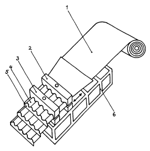
2s The machinery according to figures 1 and 2 includes the bed 6, on which is
situated the first press 2 and the second press 3. The sheet metal strip 1 is
on
a roll some distance away from the bed or as a support to the bed. The first
press 2 can travel on the bed in a lengthways direction, but the actual
transfer
equipment is not shown in the figure. This pressing tool 2 includes two
opposite
3o pressing tools that are fitted with undulated dies.

CA 02282589 2005-11-25
3a
Some distance away from the first pressing tool 2 is the second pressing tool
3
which is fixed to the bed. It is also fitted with a pair of pressing tools,
but with
this tool a step is pressed into the metal sheet.
s
When using the method according to the invention, the end of the metal sheet 1
is passed through the press 2 and on to press 3. The press 3 grips the strip
in
position and the press 2 is drawn along the length of the strip. The pressing
dies of press 2 are pressed against each other such that the strip is pressed
io between them and an undulated profile 4 is formed in the strip. The press 2
is moved some distance away, pressing against the metal strip and when at a

CA 02282589 1999-08-26
WO 98/37992 PCT/FI98/00164
4
suitable distance, for example 1-1.5 metres, the press is stopped.
After this, the latter pressing tool 3 is released and the press 2 and
the metal strip are moved forward towards the second pressing tool
until the press 2 is in its starting position. After this a stepped
longitudinal profile 5 is made in the metal strip with the latter press
3. The procedure is then repeated.
The invention is not limited to the advantageous arrangements
shown but can vary within the framework of the invention concept
1o formed by the claims.
20
30
___._.___ __W.__.._._.._ . ._ . r . . . ..~

Representative Drawing
A single figure which represents the drawing illustrating the invention.
Administrative Status

For a clearer understanding of the status of the application/patent presented on this page, the site Disclaimer , as well as the definitions for Patent , Administrative Status , Maintenance Fee  and Payment History  should be consulted.

Administrative Status

Title Date
Forecasted Issue Date 2006-11-28
(86) PCT Filing Date 1998-02-25
(87) PCT Publication Date 1998-09-03
(85) National Entry 1999-08-26
Examination Requested 2003-02-25
(45) Issued 2006-11-28
Deemed Expired 2010-02-25

Abandonment History

Abandonment Date Reason Reinstatement Date
2002-02-25 FAILURE TO PAY APPLICATION MAINTENANCE FEE 2002-09-18

Payment History

Fee Type Anniversary Year Due Date Amount Paid Paid Date
Registration of a document - section 124 $100.00 1999-08-26
Application Fee $150.00 1999-08-26
Maintenance Fee - Application - New Act 2 2000-02-25 $50.00 2000-02-23
Maintenance Fee - Application - New Act 3 2001-02-26 $50.00 2001-01-26
Reinstatement: Failure to Pay Application Maintenance Fees $200.00 2002-09-18
Maintenance Fee - Application - New Act 4 2002-02-25 $50.00 2002-09-18
Maintenance Fee - Application - New Act 5 2003-02-25 $75.00 2003-02-20
Request for Examination $200.00 2003-02-25
Maintenance Fee - Application - New Act 6 2004-02-25 $200.00 2004-02-18
Maintenance Fee - Application - New Act 7 2005-02-25 $200.00 2005-01-27
Maintenance Fee - Application - New Act 8 2006-02-27 $200.00 2006-02-01
Expired 2019 - Corrective payment/Section 78.6 $575.00 2006-07-05
Final Fee $300.00 2006-09-14
Maintenance Fee - Patent - New Act 9 2007-02-26 $200.00 2007-02-16
Maintenance Fee - Patent - New Act 10 2008-02-25 $450.00 2008-09-03
Owners on Record

Note: Records showing the ownership history in alphabetical order.

Current Owners on Record
SUUNNITTELUTOIMISTO TUOMO TOIVANEN OY
Past Owners on Record
TOIVANEN, TUOMO
Past Owners that do not appear in the "Owners on Record" listing will appear in other documentation within the application.
Documents

To view selected files, please enter reCAPTCHA code :


To view images, click a link in the Document Description column. To download the documents, select one or more checkboxes in the first column and then click the "Download Selected in PDF format (Zip Archive)" or the "Download Selected as Single PDF" button.

List of published and non-published patent-specific documents on the CPD .

If you have any difficulty accessing content, you can call the Client Service Centre at 1-866-997-1936 or send them an e-mail at CIPO Client Service Centre.


Document
Description 
Date
(yyyy-mm-dd) 
Number of pages   Size of Image (KB) 
Representative Drawing 1999-10-29 1 7
Abstract 1999-08-26 1 49
Description 1999-08-26 4 177
Claims 1999-08-26 1 32
Drawings 1999-08-26 2 26
Cover Page 1999-10-29 1 42
Description 2005-11-25 5 185
Claims 2005-11-25 1 27
Representative Drawing 2006-03-21 1 8
Cover Page 2006-11-01 1 40
Correspondence 2006-09-14 1 39
Assignment 1999-08-26 5 161
PCT 1999-08-26 9 343
Prosecution-Amendment 2003-02-25 1 25
Fees 2002-09-18 1 50
Correspondence 2004-02-18 1 31
Prosecution-Amendment 2005-05-30 2 54
Prosecution-Amendment 2005-11-25 5 132
Prosecution-Amendment 2006-07-05 2 57
Correspondence 2006-07-21 1 16
Fees 2008-09-03 1 39