Note: Descriptions are shown in the official language in which they were submitted.
CA 02282954 1999-09-22
JET MILL
BACKGROUND OF THE INVENTION
1. Field of the Invention
The present invention relates to a jet mill of a horizontal
turning flow type.
2.Description of the Prior art
Recently, various types of jet mills have been developed,
which are used in various fields such as generation, etc., of
powder poor in heat such as agrichemicals, toner, etc., or
ceramic powder and micro-crushed powder by bringing it into
collision with each other by high speed jet.
For example, Japanese Patent Publication No. 16981 of 1988
(hereinafter called Publication "A") discloses "an ultrasonic
jet mill in which a circumferential part of a circular separation
chamber is caused to face a collision space between a collision
plate opposed to the outlet of a main nozzle for high pressure
gas jetting and the nozzle outlet, and the circular separation
chamber are caused to communicate with the outlet side of a
material feeding passage communicating with midway of the main
nozzle in a bypass passage extending in the circumferential
tangential direction of the circular separation chamber, and
a discharge passage of micro powder is connected to the middle
CA 02282954 1999-09-22
portion of said circular separation chamber. In addition, as
a construction similar thereto, Japanese Laid-Open Patent
Publication Nos. 50554 of 1982, 50555 of 1982, 50556 of 1982,
290560 of 1992, 184966 of 1993, 275731 of 1995, 152742 of 1996,
155324 of 1996, 182937 of 1996, 254855 of 1996, 323234 of 1996,
Japanese Utility Model Publication Nos. 52110 of 1991, 53715
of 1995, 8036 of 1995, and Laid-Open Utility Model Publication
No. 19836 of 1994 have been known.
Japanese Patent Publication No. 17501 of 1988 (hereinafter
called Publication "B") discloses "a jet mill having, at one
end thereof, a solid and gas blending chamber formed, in which
a material feeding port and a crushed material feeding nozzle
for jetting a high pressure gas are opened adjacent to each other,
and, at the other end, a turning and crushing chamber is formed,
in which a collision plate is provided and a crushing nozzle
for jetting a high pressure gas is disposed, wherein one end
of the solid and gas blending chamber is caused to communicate
with one end of the turning and crushing chamber by an
accelerator tube opposite to the collision plate, a screening
chamber which communicates with the turning and crushing
chamber is formed via a rectification zone on the outer
circumference of the accelerator tube, and further an annular
screening plate which encloses the accelerator tube is provided
in the screening chamber with its interior communicated with
-2-
CA 02282954 1999-09-22
the discharge hole and its exterior communicated with the solid
and gas blending chamber.
Japanese Patent Publication No. 9057 of 1989 (hereinafter
called Publication "C") improves the jet mill disclosed by
Patent "B" and discloses "a jet mill provided with a projection
(center pole), the center portion of which protrudes mostly
toward the center of the outlet of the accelerator, on the
collision plate".
Japanese Laid-Open Patent Publication No. 254427 of 1994
(hereinafter called Publication "D") discloses "a jet mill
comprising a plurality of crushing nozzles for forming turning
flows by jetting a high pressure gas into a turning and crushing
chamber, and a collision member provided opposite to the jetting
portions of the respective crushing nozzles, wherein the
collision member is a flat collision plate, the shape at the
downward end and upward end along the turning flow direction
of which is formed to be thin like a blade, the collision face
is located in the flow direction of the turning flows, and is
inclined so that an angle a formed by the collision face and
the center line of the crushing nozzles opposite thereto in a
range from 30 to 60 degrees, and the collision member is disposed
and fixed by an attaching means, the angle of which is
adjustable."
Japanese Laid-Open Patent Publication No. 111459 of 1990
-3-
CA 02282954 1999-09-22
(hereinafter called Publication "E" ) discloses "a jet mill in
which the widening angle of an accelerator tube is formed to
be 7 through 9 degrees." In addition, Japanese Utility Model
Publication No. 25227 of 1995 is known as its equivalent.
Further, a prior art jet mill was such that crushed material
feeding nozzles and jet nozzles for jetting a high pressure gas
were designed and arranged so that jet nozzles are disposed at
positions where the circumference of a turning and crushing
chamber is equally divided, and crushed material feeding
nozzles are disposed one by one between each of the two
equidistantly disposed jet nozzles, wherein the total number
of nozzle is designed to be an odd number.
However, the abovementioned prior art jet mill has the
following shortcomings and problems;
The jet mill as set forth in Publication "A" has a problem
and/or a shortcoming by which, if a crushed material, for example,
a new ceramic crushed material having high hardness is brought
into collision with a fixing wall in line with a jet stream of
a high pressure gas, the part of the fixing wall, with which
the crushed material is brought into collision, is recessed by
wearing, the fixing wall is damaged in a short time, and the
durability thereof is remarkably impaired.
The jet mill as set forth in Publication "B" also has a problem
and/or a shortcoming similar to that of Publication "A", and
-4-
CA 02282954 1999-09-22
another problem by which, since materials are fed to the middle
portion (pressure-reduced portion) of a turning air stream,
crushed micro powder may be accumulated at the middle portion
to worsen the screening efficiency, and the grain size
distribution is remarkably widened.
In the jet mill as set forth in Publication "C", since both
feeding of crushed materials and discharge of micro powder are
carried out at the upper part of the turning and crushing chamber,
normal streams of the turning flows which form crushing nozzles
greatly fall into disorder, such disorder of the turning flows
increases pressure loss, resulting in a lowering of the speed
of the turning flows, whereby the crushing capacity is
decreased.
In the jet mill as set forth in Publication "D", the crushing
efficiency is excellent in that a collision action effected by
four collision plates secured in the turning and crushing
chamber is utilized. However, the speed of the turning flows
of a high speed jet is lowered due to the existence of the
collision plates, and the shape of crushed powder becomes square,
and such a problem arises, by which it becomes difficult to
adjust the grain size distribution.
Further, if the number of prior art crushed material feeding
nozzles and jetting nozzles disposed is an odd number, since,
after turning flows are formed by an even number of crushing
-5-
CA 02282954 1999-09-22
nozzles, a solid and gas multi-phase flow is pressed into the
turning and crushing chamber by one crushed material feeding
nozzle, such a problem arises, by which segregation of turning
flows due to said solid and gas multi-phase flows pressed into
later on is likely to occur, and at the same time, the high
pressure gas amount of the crushed material feeding nozzles and
jetting nozzles must be separately established, the operation
control becomes cumbersome, whereby the operation efficiency
is spoiled. In addition, since the number of nozzles is an odd
number, segregation is also likely to occur, wherein another
problem arises, by which the crushing efficiency and screening
efficiency are impaired.
In addition, since the respective jetting nozzles are
provided with only one jetting port, a turning and crushing
chamber is produced on the basis of flow lines of turning flows
being two-dimensionally understood and analyzed as one line.
Therefore, the velocity at the upper part ( top liner portion )
and the lower part (bottom liner portion) of the turning and
crushing chamber is lowered. Accordingly, such a problem arises,
by which a stay duration of large grains in the turning and
crushing chamber is made longer, and the liner portions at the
upper part and lower part is remarkably worn.
Further, since adjustment of the grain size of micro powder
is carried out by changing only the pressure or volume of a jet
-6-
CA 02282954 1999-09-22
stream in either type, segregation of turning flows and pressure
fitting of micro powder to the inner walls of the turning and
crushing chamber are liable to occur by characteristics of
crushed materials, such shortcomings and/or problems arise,
which causes a remarkable wearing of liner portions such as ring
liners of the turning and crushing chamber, the top liner, and
bottom liner, whereby continuous stabilized operation becomes
impossible.
SUMMARY OF THE INVENTION
The present invention solves these shortcomings and problems
described above.
It is therefore an object of the invention to provide a jet
mill which remarkably improves the crushing treatment capacity
and ensures continuous treatment for a longer period of time,
wherein no segregation arises, high crushing efficiency and
screening efficiency are obtained, micro powder having a narrow
grain size distribution can be remarkably and efficiently
produced, the velocity distribution of solid and gas multi-
phase flows in the turning and crushing chamber can be made
uniform, the collision dependency of crushed materials on the
inner wall surface of the turning and crushing chamber can be
lowered, the collision dependency among crushed materials can
be increased, and whereby a wearing of the wall surfaces can
_7_
CA 02282954 1999-09-22
be prevented, micro powder can be remarkably prevented from
being pressure-fitted, and a stay duration in the turning and
crushing chamber can be shortened.
With a jet mill according to the invention as described above,
the following excellent effects can be achieved.
According to the jet mill as set forth in Claim 1 of the
invention;
(1) Since a distance 1 between the venturi nozzle lead-
in portion of the solid and gas blending chamber and the
discharge side of the press-in nozzle is expressed in terms of
1 = (D/d) x k, and value k is formed so that it can meet k=7
through 12, preferably, k=8 through 10 (where D is the diameter
of the venturi nozzle lead-in portion, and d is the diameter
of the press-in nozzle at the discharge side), both the venturi
nozzles and crushing nozzles are caused to enter a standby status
by the same pneumatic pressure at the same time, materials to
be crushed can be sucked in regardless of types of the crushing
materials, whereby continuous operation is enabled.
According to a jet mill as set forth in Claim 2 of the invention,
in addition to the effects described in Claim 1,
(2) Since a negative pressure generating portion is
provided between the throat portion of the venturi nozzle and
the venturi nozzle lead-in portion (upstream side), the
materials are sucked in from the press-in nozzle of the crushed
_8_
CA 02282954 1999-09-22
material by high speed jet streams without leaking to the venturi
nozzles, whereby it is possible to feed the materials into the
turning and crushing chamber in a stable state at a high speed.
According to a jet mill as set forth in Claim 3 of the invention,
in addition to the effects described in Claim 1 or 2,
(3) Since the respective nozzles are equidistantly disposed
on the peripheral wall of the turning and crushing chamber
without being biased as in the prior arts, pressure jetted from
the crushing nozzles and venturi nozzles into the system is
synchronized and well-balanced, no segregation of turningflows
is caused to arise. Resultantly, the running operation can be
facilitated, and at the same time, the dependency of crushing
materials on collision with the wall surface is lowered, and
the dependency on collision among grains can be increased.
Therefore, a wearing of the liner portion in the turning and
crushing chamber can be remarkably suppressed. In addition,
since crushing materials can be prevented from being segregated
in the turning and crushing chamber, the crushing efficiency
is improved to increase the screening efficiency.
According to the jet mill as set forth in Claim 4 of the
invention, in addition to the effects described in any one of
Claims 1 through 3,
( 4 ) Turning flows in the crushing zone and screening zone
in the turning and crushing chamber can be three-dimensionally
_g_
CA 02282954 1999-09-22
controlled, the shape of grains can be made round and the grain
size distribution can be narrowed. In addition, it is possible
to freely control the range of grain size distribution.
(5) Since a multiple step jetting portion is employed in
a multiple-row crushing nozzle, a stream line in the turning
and crushing chamber is three-dimensionally obtained as
multiple layers, whereby a difference in speed in the height
direction in the mill is decreased to shorten the stay duration
of grains in the mill, and the crushing treatment capacity can
be improved.
According to the jet mill as set forth in Claim 5 of the
invention, in addition to the effects described in any one of
Claims 1 through 4,
( 6 ) Since the crushing nozzles are of multiple rows and the
jetting angle of the respective portions are different from each
other, it is possible to control the three-dimensional shape
and speed of crushing and turning flows in terms of the
horizontal surface and height. Since solid and gas multi-phase
turning flows are three-dimensionally controlled, optimal
turning flows can be formed in compliance with various types
of crushed materials having different physical properties, and
it is possible to adjust the grain size and to prevent micro
powder from being pressure-fitted. Further, since no
segregation arises, it is possible to prevent the liner portions
-10-
CA 02282954 1999-09-22
from being worn.
(7) Since at least one of the diameters and/or jetting
angles of the jetting ports of the respective rows of crushing
nozzles is different from each other, the dependency on
collision among materials to be crushed in turning flows can
be improved, and at the same time optimal turning flows can be
formed in compliance with various types of crushed materials
having different physical properties.
(8) Since the diameter (calibration) of the respective
jetting ports of the crushing nozzles can be changed, the
diameter of the lower side jetting ports is made greater to
increase the blow air volume with respect to crushing materials
such as ceramic having a heavy specific gravity, and the diameter
of the upper side jetting ports is made greater to increase the
collision frequency among the crushing materials with respect
to those having a light specific gravity such as coke and carbon
for electrodes and toner, etc., whereby it is possible to obtain
micro powder having a narrow grain size distribution in a short
time.
( 9 ) Since the jetting angles can be changed for each of the
rows by changing only the crushing nozzles, the turning flows
in the jet mill can be controlled for each of the materials to
be crushed having different physical properties, whereby the
turning flows suitable for the respective crushed materials can
CA 02282954 1999-09-22
be formed.
According to the jet mill as set forth in Claim 6 of the
invention, in addition to the effects described in Claim 4 or
5,
(10) By only inserting a plug in plug insertion holes,
optimal crushing conditions can be obtained in compliance with
the material to be crushed.
According to the jet mill as set forth in Claim 7 of the
invention, in addition to the effects described in any one of
Claims 1 through 6,
( 11 ) Since the center pole on the upper surface of the turning
and crushing chamber and the outlet on the underside of the
turning and crushing chamber are formed on the center line of
the turning and crushing chamber, it is possible to clearly
divide the turning and crushing chamber into a screening zone
and a crushing zone, micro powder of an appointed grain size
and having a narrow grain size distribution can be discharged
through the outlet at the upper part of the turning and crushing
chamber, and at the same time, coarse powder can be scattered
to the outer circumference by a centrifugal force generated by
high speed jet streams, wherein the dependency on collision
among materials in the high speed jet streams can be improved.
A jet mill as set forth in Claim 1 of the invention which
is a jet mill of a horizontal turning flow type is provided with
-12-
CA 02282954 1999-09-22
a hollow disk-shaped turning and crushing chamber; a plurality
("m") of crushing nozzles, the jetting ports of which are
inclined to the circumferential wall and disposed at the side
wall of the turning and crushing chamber, for forming turning
flows by jetting a high pressure gas; a plurality ("n") of
venturi nozzles (where m+n = a, a is an integral number, and
m) n) for introducing materials to be crushed, in line with high
pressure gas, which are disposed at the side wall of the turning
and crushing chamber; a solid and gas blending chamber, which
is formed at the upstream side of said venturi nozzles; a crushed
material supplying portion communicating with said solid and
gas blending chamber; a press-in nozzle disposed in said solid
and gas blending chamber coaxially with said venturi nozzles;
and an outlet, disposed at the upper part of the center portion
of said turning and crushing chamber, which discharges micro
powder, wherein a distance 1 between a venturi nozzle lead-
in portion of said solid and gas blending chamber and the
discharge side of said press-in nozzle is expressed in terms
of 1=(D/d) x k, a value k is formed so as to meet k=7 through
12, preferably, k=8 through 10 (where D is the diameter of the
venturi nozzle lead-in portion, and d is the diameter of the
press-in nozzle at the discharge side).
Thereby, a distance 1 between a venturi nozzle lead-in
portion of said solid and gas blending chamber and the discharge
-13-
CA 02282954 1999-09-22
side of said press-in nozzle is expressed in terms of 1=(D/d)
x k, a value k is formed so as to meet k=7 through 12, preferably,
k=8 through 10 (where D is the diameter of the venturi nozzle
lead-in portion, and d is the diameter of the press-in nozzle
at the discharge side) . Therefore, both the venturi nozzles and
crushing nozzles are simultaneously caused to enter a standby
state at the same air pressure, and crushed materials can be
smoothly sucked regardless of the kind of crushed materials,
whereby continuous operation can be carried out.
Herein, the distance 1 between the venturi nozzles and
press-in nozzles is a distance between the inlet of the venturi
nozzle lead-in portion and the tip end portion of the press-in
nozzles, which is expressed in terms of (D/d) x k = 1, where
k is 7 through 12, preferably, 8 through 10. It is recognized
that, as the k becomes smaller than 8, the sucking force of
crushed materials is weakened, and as k becomes greater than
10, high pressure jet streams from the press-in nozzles
completely escape from the venturi nozzles, wherein a pressure
loss can be recognized. It is obtained from analysis and
experimental results of a jet mill that either case is not
preferable.
Iron-based, aluminum-based, copper-based, titanium-based
metals and alloys or those combined with ceramics may be listed
as materials for the turning and crushing chamber, crushing
-14-
CA 02282954 1999-09-22
nozzle, press-in nozzles, and venturi nozzles. In particular,
a hard alloy is preferable in view of wear resistance.
An inactive gas such as air, nitrogen, argon, etc., may be
used as a high pressure gas, in compliance with the kind of
materials to be crushed and crushing conditions.
A jet mill as set forth in Claim 2 of the invention has such
a construction where the venturi nozzles are provided with a
negative pressure generating portion between a throat portion
and the venturi nozzle lead-in portion in addition to an
invention set forth in Claim 1.
Therefore, since the negative pressure generating portion
is provided between the throat portion of the venturi nozzle
and the venturi nozzle lead-in portion (upstream side) in
addition to the actions obtained in Claim l, crushed materials
are sucked into the venturi nozzles by high speed jet streams
from the press-in nozzles without leakage, whereby the crushed
materials can be fed into the turning and crushing chamber at
a high speed in a stabilized state.
Herein, the negative pressure generating pressure is formed
between the throat portion of the venturi nozzles and the lead-in
portion, and an inclination angle 8 1 of the inlet ( rear portion
of the negative pressure generating portion) of the throat
portion and an inclination angle 62 of the outlet of the throat
portion are expressed in terms of 0 . 5 ° ~ B 1 <__ 8 z, preferably 0 .
7
-15-
CA 02282954 1999-09-22
2 to the axis of the venturi nozzle. In addition, 8
z is formed to 2.5° through 6° , preferably, 3° through
5° .
As the 81 becomes smaller than 0 . 7 ° , the amount of negative
pressure is decreased, and the suction is liable to become short,
and as the 8 2 becomes greater than 5 ° , s imilarly, the amount
of negative pressure is decreased, and the suction is liable
to become short. Either case is not preferable.
As 92 becomes smaller than 3° , a pressure loss arises at
the inlet of the lead-in portion, and no function of the negative
pressure generating portion can be obtained, thereby causing
the crushing capacity to be lowered. In addition, as 62 becomes
greater than 5° , the velocity of solid and gas multi-phase flows
is lowered, thereby causing the crushing capacity to be
decreased. Either case is not preferable.
The length g of the negative pressure generating portion is
2 through 4 .2 times the diameter D of the venturi nozzle lead-in
portion, preferably 2.2 through 3.8 times, and the length h of
the throat portion is 2.25 through 5 times the diameter a of
the inlet of the throat portion, preferably 3 or 4 times.
As the length g of the negative pressure generating portion
becomes smaller than 2.2 times the diameter D of the venturi
nozzle lead-in portion, a turning flow occurs at the lead-in
portion, whereby the negative pressure for suction is likely
to be decreased, and as the length g becomes greater than 3.8
-16-
CA 02282954 1999-09-22
times, pressure fitting at the negative pressure generating
portion is likely to occur. Either case is not preferable.
As the length h of the throat portion becomes smaller than
3 times the diameter a of the inlet of the throat portion, the
negative pressure is likely to be decreased by being influenced
by the discharge portion, and as the length h becomes greater
than four times, pressure fitting is likely to occur at the
throat portion. Either case is not preferable.
A jet mill as set forth in Claim 3 of the invention is
constructed so that, in addition to the invention described in
Claim 1 or 2, the total number m+n of the crushing nozzles and
the venturi nozzles is an even number, and 5<-_m~15, 1~n~5,
and preferably, 5 <m< 14 , 1 ~ n ~ 2 .
Therefore, since the respective nozzles are equidistantly
disposed on the circumferential wall of the turning and crushing
chamber without being biased as in the prior arts, in addition
to the actions obtained in Claim 1 or 2, it is possible to
synchronize pressure jetted into a system from the crushing
nozzles and venturi nozzles and to secure balance, the turning
flows can be freed from any segregation, resulting in an easiness
of the running operations, and further, the collision
dependency of materials to be crushed, on the wall surface can
be decreased, and the dependency on collisions among grains is
increased, whereby a wearing of the liner portions in the turning
-17-
CA 02282954 1999-09-22
and crushing chamber can be remarkably suppressed. In addition,
since crushed materials can be prevented from being segregated
in the turning and crushing chamber, the crushing efficiency
can be improved to heighten the screening efficiency.
Herein, as the quantity of crushing nozzles is decreased from
5, it can be recognized that controllability of the shape and
speed of turning flows is likely to be impaired, and if the
quantity exceeds 14, the structure of the jet mill becomes
cumbersome, whereby it can be recognized that there is a tendency
for the solid and gas multi-phase flows to be less controlled.
Either case is not preferable.
A jet mill as set forth in Claim 4 of the invention has such
a construction where the respective crushing nozzles are
provided with "p" steps ( however, 2 <__p< 5 ) of jet portions in
the vertical direction and/or "q" rows (however, 1~ q ~5) of
jetting portions in the cross direction, in addition to the
invention described in any one of Claims 1 through 3.
Therefore, in addition to the actions obtained by any one
of Claims 1 through 3, it is possible to three-dimensionally
control the turning flows in the crushing zone and the screening
zone in the turning and crushing chamber, and at the same time
the shape of grains can be rounded to narrow the grain size
distribution, whereby such an action can be obtained, by which
it is possible to freely control the range of the grain size
_18_
CA 02282954 1999-09-22
distribution.
Since the respective crushing nozzles have multiple steps
and/or multiple rows of jetting portions, the stream lines in
the turning and crushing chamber can be three-dimensionally
obtained as multiple step layers, and a difference in the
velocity can be decreased in the height direction in the jet
mill, thereby shortening the stay duration of grains in the mill .
Therefore, such an action can be obtained, by which the crushing
treatment capacity can be improved.
Herein, the number of steps (p) of jetting portions of
crushing nozzles is 2 <__p<_-5, preferably p=3 . If the number of
steps is smaller than 2, the velocity of turning flows in the
vertical direction in the turning and crushing chamber is likely
to become lower than that at the middle portion, and if the number
exceeds 4 or the number of rows (q) of jetting portions exceeds
rows, the balance of the turning flows can be hardly secured,
and it becomes impossible to three-dimensionally control the
turning flows. Accordingly, either case is not preferable.
A jet mill as set forth in Claim 5 of the invention has such
a construction wherein, in addition to the invention described
in any one of Claims 1 through 4, at least one of the calibrations
( diameter ) of the jetting ports of the respective rows and/or
steps of the jetting portion and/or a jetting angle of the
jetting portion is formed so as to differ from each other.
-19-
CA 02282954 1999-09-22
Therefore, in addition to the actions obtained by any one
of Claims 1 through 4, since at least one diameter (calibration)
of jetting ports of the respective jetting portions at the
respective steps of the crushing nozzles differs from each other,
the shape and speed of three-dimensional crushing and turning
flows of the horizontal surface and height can be controlled.
Hy three-dimensionally controlling the solid and gas multi-
phase turning flows, optimal turning flows can be formed in
compliance with various types of materials to be crushed having
different physical properties. Therefore, it is possible to
adjust the grain size and to prevent micro powder from being
pressure-fitted, and since no segregation exists, it is
possible to prevent the liner portions from wearing.
In addition, since at least one of the jetting angles of the
respective rows of crushing nozzles differs from each other,
the collision dependency among materials to be crushed in the
turning flows can be improved, and optimal turning flows can
be formed in compliance with various types of crushed materials
having different physical properties.
Since the diameter (calibration) of the jetting ports and
jetting angles of the respective rows and steps of the crushing
nozzles are clogged by a plug, etc., at the upstream side, the
jetting diameter and jetting angle in response to the crushed
materials can be changed, whereby the diameter of the downstream
-20-
CA 02282954 1999-09-22
side jetting ports is made greater with respect to materials
such as ceramic whose specific gravity is heavy to increase the
blow volume, and in a case where the specific gravity of
materials is light such as coke and carbon for electrodes and
toner, etc., the diameter of the upstream side jetting ports
is made greater to increase the collision frequency of crushed
materials, whereby such an action can be obtained, by which micro
powder having narrow grain size distribution can be obtained
in a short time.
Since the jetting angle can be changed for each of the rows
by only changing the crushing nozzles, it is possible to control
the turning flows in the turning mill for each of the materials
to be crushed, having different physical properties, and such
an action can be obtained, by which turning flows suitable for
the respective materials to be crushed can be formed.
Herein, since the jetting angle of the jetting portions in
the respective rows of the crushing nozzles can be adjusted in
a range from 20° through 80° by changing the crushing nozzles,
the collision dependency among crushed materials in the turning
flows can be adjusted. The diameter (calibration) of the jetting
ports of the respective rows is established to be 0 . 3q~ <- qP
~2.1q~ where it is assumed that the blow volume of the press-in
nozzles is qP and the blow volume of one crushing nozzle is q~.
Herein, generation of negative pressure of the venturi nozzles
-21-
CA 02282954 1999-09-22
is decreased as qP becomes smaller than 0.3q~, wherein suction
of the crushed materials is likely weakened. In addition, it
is recognized that the turning flows in the jet mill are
disordered as qP becomes grater than 2.1 q~. Either case is not
preferable.
As the jetting angle of the jetting portions in the respective
rows of the crushing nozzles becomes smaller than 20° , the
velocity of the crushing and turning flows is lowered, crushed
materials are segregated in the turning and crushing chamber
to lower the crushing efficiency. And as the jetting angle
becomes greater than 80° , a wearing of the ring liners in the
turning and crushing chamber is increased. Either case is not
preferable.
Further, in order to secure universality of the crushing
nozzles, jetting angles of the jetting portions in the
respective row, 22.5° (for crushed materials which are likely
to be segregated or are difficult to be separated), 45° (for
crushed materials, whose hardness is high, causing the liner
portions to be easily worn ) , and 67 . 5 ° ( for materials having a
pressure-fitting characteristic) are combined, whereby it is
possible to efficiently crush materials from a high specific
gravity and a small specific gravity.
A jet mill as set forth in Claim 6 of the invention has such
a construction where, in addition to the constructions
-22-
CA 02282954 1999-09-22
described in Claim 4 or 5, the jetting portions of the crushing
nozzles have a plug inserting hole formed at the upstream side.
Therefore, in addition to the action obtained by any one of
Claims 4 and 5, such an action can be obtained, by which the
crushing conditions best suitable for materials to be crushed
can be obtained by only inserting a plug in the plug inserting
hole.
It is preferable that a plug used herein may be made of metal,
synthetic resin, etc.
A jet mill as set forth in Claim 7 of the invention is provided
with a center pole disposed at the middle of the underside of
said turning and crushing chamber, in addition to the
construction described in any one of Claims 1 through 6, wherein
the top point of the center pole and the lower end face of the
outlet are located on the center line in the height direction
of the turning and crushing chamber.
Therefore, in addition to the actions described in any one
of Claims 1 through 6, the turning and crushing chamber can be
clearly divided into a screening zone and a crushing zone by
forming the center pole on the upper surface of the turning and
crushing chamber and outlet on the under surface of the turning
and crushing chamber so that they are disposed on the center
line of the turning and crushing chamber, whereby micro powder
of an appointed grain size and that having narrow grain size
-23-
CA 02282954 1999-09-22
distribution can be discharged through the outlet on the upper
part of the turning and crushing chamber, and at the same time,
coarse grains are scattered to the outer circumference by a
centrifugal force generated by high jet streams, and collision
dependency among materials in the high speed jet streams can
be improved.
Herein, iron-based, aluminum-based, copper-based,
titanium-based metals or alloys or those combined with ceramic
may be listed as materials of the outlet and center pole. In
particular, a hard alloy is preferable in terms of wear
resistance.
BRIEF DESCRIPTION OF THE DRAWINGS
In the accompanying drawings:
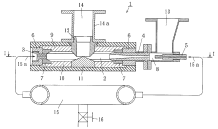
Fig. 1 is a sectional view of major parts of a jet mill
according to the first preferred embodiment of the invention;
Fig. 2 is a cross-sectional view of major parts, taken along
the line I-I in Fig. 1;
Fig. 3 is a sectional view of major parts of a solid and gas
blending chamber of the jet mill according to the first preferred
embodiment of the invention;
Fig. 4 is a sectional view of major parts of a venturi nozzle
of the jet mill according to the first preferred embodiment of
the invention;
-24-
CA 02282954 1999-09-22
Fig. 5 is a sectional view of major parts of the jet mill
according to the second preferred embodiment of the invention;
Fig. 6 is a cross-sectional view of major parts taken along
the line II-II in Fig. 5,
Fig. 7(a) is a perspective view of the rear side of a crushing
nozzle according to the second preferred embodiment of the
invention, Fig. 7(b) is a bottom view of the crushing nozzle,
and Fig. 7(c) is a cross-sectional view of major parts, taken
along the line III-III in Fig. 7(b);
Fig. 8 is an exemplary view showing a relationship between
the diameter of jetting ports of one row and turning flows of
a complex crushing nozzle according to the invention;
Fig. 9 ( a ) is a sectional view of major parts of an assembled
crushing nozzle body according to the second preferred
embodiment of the invention; Fig . 9 ( b ) is a bottom view of the
assembled crushing nozzle body; Fig. 9 ( c ) is a front elevational
view of the assembled crushing nozzle view; and Fig. 9(d) is
a sectional view of major parts of an insertion type jetting
portion of the assembled crushing nozzle;
Fig. 10 is a view showing a relationship between the grain
size and grain size accumulation (~) of micro powder crushed
by second preferred embodiment according to the invention and
comparative example 2;
Fig. 11 is a view showing the dependency of micro powder on
-25-
CA 02282954 1999-09-22
the grain size distribution ( ~ ) at a pressure of 7 .5kgf/cm2 of
high speed jet streams according to the third preferred
embodiment of the invention; and
Fig. 12 is a view showing the dependency of micro powder on
the grain size distribution ( o ) at a pressure of 4.5kgf/cmz of
high speed jet streams according to the third preferred
embodiment of the invention.
PREFERRED EMBODIMENTS OF THE INVENTION
Hereinafter, a description is given of the preferred
embodiments of the invention with reference to the drawings.
(Embodiment 1)
A jet mill according to a first preferred embodiment of the
invention is described with the accompanying drawings.
Fig. 1 is a sectional view of major parts of a jet mill
according to the first preferred embodiment of the invention,
Fig. 2 is a cross-sectional view of major parts, taken along
the line I-I in Fig. 1, Fig. 3 is a sectional view of major parts
of a solid and gas blending chamber in a jet mill according to
the first preferred embodiment of the invention. Fig. 4 is a
sectional view of major parts of venturi nozzles of a jet mill
according to the first preferred embodiment.
In Fig. 1, a jet mill according to the first preferred
embodiment is indicated by 1. A turning and crushing chamber
-26-
CA 02282954 1999-09-22
2 is formed hollow and disk-shaped, seven crushing nozzles 3
are equidistantly disposed in the turning and crushing chamber
2, a venturi nozzle 4 is disposed in the turning and crushing
chamber 2, a press-in nozzle 5 is disposed coaxially with the
venturi nozzle 4 via a solid and gas blending chamber 8 at the
upstream side of the venturi nozzle 4, a body casing is indicated
by 6, a ring liner of the turning and crushing chamber 2 is
indicated by 7, a solid and gas blending chamber is indicated
by 8, a top liner 9 and a bottom liner 10 are disposed
perpendicularly in the turning and crushing chamber 2, a center
pole 11 is such that its upper part detachably disposed at the
middle of the bottom liner 10 is formed to be roughly conical,
an outlet 12 is formed coaxially with the center pole 11 and
is detachably disposed at the top liner 9, a crushing material
lead-in port 13 communicates with the solid and gas blending
chamber 8, a micro powder discharge port 14 is formed by a sleeve
14a, a high pressure header tube is indicated by 15, a high
pressure gas pipe 15a feeds a high pressure gas from the high
pressure header tube 15 to the crushing nozzles 3 and press-in
nozzles 5, and a pressure adjusting valve 16 adjusts pressure
of the high pressure gas pipe 15a.
In Fig. 2, a is a jetting angle of the venturi nozzles, and
y is a jetting angle of the jetting portions of the crushing
nozzles. a is adjusted to 20° through 70° , preferably
30°
-27-
CA 02282954 1999-09-22
through 5 0 ° . As a becomes smaller than 3 0 ° , such a
tendency
arises, where resistance occurs in suction of multi- phase flows
and turning flows are disordered, and as a becomes greater than
50° , such a tendency arises, where pressure fitting and wearing
are likely to occur at the liner portions. Either case is not
preferable. y differs in compliance with the number of crushing
nozzles and type of materials to be crushed.
In Fig. 3, D is an inlet diameter of the upstream side opening
of the venturi nozzles 4, d is an outlet diameter of the press-in
nozzles 5, 1 means a distance between the lead-in portion of
the venturi nozzles 4, and the discharge side of the press-
in nozzles 5.
As regards the distance 1 between the lead-in portion of the
venturi nozzle 4 of the solid and gas blending chamber 8 and
the discharge side end of the press-in nozzle 5, the position
of the press-in nozzle 5 is determined so as to meet an expression
of 1 = ( D/d ) X k, wherein the value k is a value obtained through
experiments, and k=7 through 12, preferably, a value of 8 through
is employed.
In Fig. 4, 61 is an inclination angle of the inlet (the rear
portion of the negative pressure generating portion ZZ ) of the
throat portion Z3 with respect to the axial line of the venturi
nozzle, 82 is an inclination angle of the outlet of the throat
portion Z, of the venturi nozzles, 8 3 is an inclination angle
_28_
CA 02282954 1999-09-22
of the lead-in portion Z1 of the venturi nozzle, Z1 is the lead-in
portion of the solid and gas multi-phase flows, which is greatly
open to the upstream side of the venturi nozzles, Zz is a negative
pressure generating portion slightly inclined and formed with
respect to the axial line from the lead-in portion end, Z3 is
a throat portion formed roughly parallel to the axial line, Z4
is a discharge portion open from the rear portion of the throat
portion Zj, a is a diameter of the inlet of the throat portion
Z3, h is a length of the throat portion Z3, and g is a length
of the negative pressure generating portion Zz.
The inclination angle 91 of the inlet portion (the rear
portion of the negative pressure generating portion) of the
throat portion Z3 and the inclination angle 62 of the outlet
of the throat portion Z, is formed to be 0 . 5 ° <-_ 81 ~ 8 z,
preferably
0.7° < 61~ 9z with respect to the axial line of the venturi
nozzle. In addition, 62 is formed to be 2.5° through 6° ,
preferably, 3 ° through 5 ° . The length g of the negative
pressure generating portion z2 is 2 through 4.2 times the
diameter D of the venturi nozzle lead-in portion, preferably
2.2 through 3.8 times, and the length h of the throat portion
Z3 is 2.25 through 5 times the diameter a of the inlet of the
throat portion Z3, preferably 3 through 4 times.
with the jet mill according to the first preferred embodiment
constructed as described above, a description is given of the
-29-
CA 02282954 1999-09-22
actions thereof.
A high pressure gas is supplied to both the crushing nozzle
3 and press-in nozzle 5 at the same pressure by opening one
pressure adjusting valve 16 . A material to be crushed is supplied
through the material lead-in portion 13, whereby the material
and air are blended in the solid and gas blending chamber 8 by
high speed jet streams jetted from the press-in nozzle 5. The
distance 1 between the venturi nozzle 4 and the press-in nozzle
is (D x d) x k - l, wherein by meeting the relation of k= 7
through 12, preferably 8 through 10, the multi-phase flow from
the venturi nozzle 4 is well stabilized and is introduced from
the venturi nozzle 4 into the turning and crushing chamber 2
at a high speed since no pressure loss is generated at the outlet
of the turning and crushing chamber 2 and venturi nozzle 4.
Turning flows are generated in the turning and crushing chamber
2 by high speed jet streams from the crushing nozzle 3, and a
crushing zone is formed at the outer circumference of the turning
and crushing chamber 2, whereby a screening zone is formed at
the middle of the turning and crushing chamber 2. Therefore,
materials to be crushed are brought into collision with each
other by a high speed jet and turning streams, whereby micro
crushing of materials is carried out. Micro powder screened by
the screening zone is discharged from an outlet 12 of the turning
and crushing chamber through a micro powder discharge port 14,
-30-
CA 02282954 1999-09-22
and coarse powder is swiveled to the outer circumference by a
centrifugal force produced by turning, whereby the coarse
powder is brought into collision with each other, and crushing
is repeatedly carried out.
The velocity of the solid and gas multi-phase flows
introduced from the lead-in portion is increased and is jetted
into the turning and crushing chamber by the negative pressure
generating portion of the venturi nozzles. In addition, the
lead-in portion of the press-in nozzles and venturi nozzles are
maintained at an appointed distance, and at the same time, since
the solid and gas multi-phase flows are jetted into the turning
and crushing chamber without impairing the blow volume and blow
pressure of the press-in nozzles by providing the negative
pressure generating portion, the balance of the turning flows
is well controlled without being collapsed.
With the first preferred embodiment described above, smooth
solid and gas multi-phase flows of the venturi nozzle can be
achieved, high crushing efficiency andscreening efficiency are
resultantly enabled without generating any segregation, and
micro powder having narrow grain size distribution can be
obtained at a remarkably high efficiency. Further, it is
possible to make the velocity distribution of the multi-phase
flows uniform in the turning and crushing chamber. Therefore,
it is possible to provide a jet mill in which the stay duration
-31-
CA 02282954 1999-09-22
of materials to be crushed in the turning and crushing chamber
can be shortened, and the crushing treatment capacity of which
is remarkably improved.
(Embodiment 2)
A description is given of a second preferred embodiment of
the invention with the accompanying drawings.
Fig. 5 is a sectional view of major parts of a jet mill
according to the second preferred embodiment of the invention,
Fig. 6 is a cross-sectional view of major parts, taken along
the line II-II in Fig. 5, Fig. 7(a) is a perspective view of
the rear side of a crushing nozzle according to the second
preferred embodiment of the invention, Fig. 7(b) is a bottom
view of the crushing nozzle, and Fig. 7 (c ) is a cross-sectional
view of major parts, taken along the line III-III in Fig. 7 (b) .
In addition, parts which are identical to those in the first
preferred embodiment are given the same reference numbers, and
description thereof is omitted.
Fig. 5, a jet mill according to the second preferred
embodiment is indicated by 30, a complex jetting nozzle 31 is
formed so that the jetting ports are nine in total, which are
provided three steps in the vertical direction and three rows
in the horizontal direction, and seven complex jetting nozzles
31 are equidistantly disposed in the turning and crushing
chamber 2. Jetting portions 32, 33, and 34 are, respectively,
-32-
CA 02282954 1999-09-22
provided with the upper, middle and lower steps of the complex
jetting nozzle 31, and a center pole is indicated by 35 and an
outlet is indicated by 36.
In Fig. 6, a jetting port 37 of the crushing nozzle of the
first row is formed so that the jetting angle ,(3 is 67.5° . A
jetting port 38 of the crushing nozzle of the second row is formed
so that the jetting angle y is 45° . A jetting port 39 of the
crushing nozzle of the third row is formed so that the jetting
angle S is 22.5° . a is a jetting angle of the venturi nozzle.
In Fig. 7, a jetting portion of the complex jetting nozzle
31 is indicated by 40, and a plug inserting hole 41 is provided
so as to widen and open at the base portion of the jetting portion
40 of the complex jetting nozzle 31 and inserts a plug 42 in
compliance with the type and treatment conditions of materials
to be crushed. The plug is indicated by 42.
As regards a jet mill according to the second preferred
embodiment, which is constructed as described above, a
description is given of actions thereof.
Seven complex crushing nozzles 31 are installed at appointed
positions and angles at the ring liner 7 of the turning and
crushing chamber 2, wherein nine jetting ports which are
provided with three steps by three rows are formed in one complex
crushing nozzle 31. The upper step jetting portion 32 is caused
to control the upper layer of the jet mill 30 in the height
-33-
CA 02282954 1999-09-22
direction, the middle jetting portion 33 is caused to control
the middle layer of the jet mill 30 in the height direction,
and the lower step jetting portion 34 is caused to control the
lower layer of the jet mill 30 in the height direction, whereby
it is possible to three-dimensionally control the shape of
crushing and turning flows and velocity. By adjusting the
jetting angle ,(3 of the first row jetting port 37 of the complex
crushing nozzle 31 in a range from 50° through 80° , it is
possible to control the collision dependency of materials to
be crushed with the ring liner 7 of the turning and crushing
chamber. By adjusting the jetting angle y of the second row
jetting port 38 of the complex crushing nozzle 31 in a range
from 30° through 60° , it is possible to control the collision
dependency among materials to be crushed in turning flows . By
adjusting the jetting angle ~ of the third row jetting port
39 of the complex crushing nozzle 31 in a range from 20° through
50° , it is possible to control the stay duration of the
materials in the jet mill. Turning flows are generated in the
turning and crushing chamber 2 by high speed jet streams from
the respective jetting ports of the complex crushing nozzles
31, and a crushing zone is formed on the inner circumferential
side of the turning and crushing chamber 2, whereby a screening
zone is formed at the middle side of the turning and crushing
chamber 2. Materials are brought into collision with each other
-34-
CA 02282954 1999-09-22
by the high speed jets and turning flows, and crushing of the
materials is carried out . Micro powder screened by the screening
zone is discharged from the outlet 36 of the turning and crushing
chamber through the micro powder discharge port 14a, and coarse
powder is turned to the outer circumference by a centrifugal
force generated by turning, whereby the materials to be crushed
are colliding with each other, and crushing is repeatedly
carried out.
Further, by inserting the plug 42 into the insertion hole
40, the jetting angle and number of jetting ports of the jetting
portion are controlled to form turning flows suitable for
various types of powder.
Next, a description is given of situations of turning flows
in a case where the jetting portion of crushing nozzles is formed
of one row, and the diameter of the jetting portion of the
respective jetting portion is changed.
Fig. 8 is an exemplary view showing a relationship between
the diameter of jetting ports of one row of the complex crushing
nozzle and turning flows.
In Fig. 8, it is found that turning flows suitable for
materials to be crushed can be obtained, by changing the diameter
of jetting ports of one row of the crushing nozzles 31 in the
respective steps.
In the case of a, since turning flows are uniformly formed
-35-
CA 02282954 1999-09-22
on the entire layer, it is possible to crush various types of
materials to be crushed, at a high efficiency.
In the case of b, since a great deal of blow air can be obtained,
it is suitable for materials having a light specific gravity
such as toner, carbon, etc.
In the case of c, since a great deal of blow air is given
to the lower layer, it is suitable for materials having a heavy
specific gravity such as fine ceramic, etc.
In the case of d, this is suitable for blended materials of
powder having several different specific gravities.
In the case of e, this is suitable for crushing of various
types of materials to be crushed, by utilizing only a small
driving force.
In the case of f, this is suitable for materials to be crushed,
having a heavy specific gravity, and the dispersion
characteristics of which are not good.
In the case of g, this is suitable for materials to be crushed,
of fragile powder, having a light specific gravity.
Herein, it is found through confirmation tests that the
diameter ratio for large, medium and small diameters is a : b : c
- a:1.5 through 3a:3 through 6a where a is a small diameter,
b is a medium diameter and c is a large diameter.
Next, a description is given of a modified version of the
second preferred embodiment with reference to the accompanying
-36-
CA 02282954 1999-09-22
drawings.
Fig. 9(a) is a sectional view of the major parts of an
assembled crushing nozzle body of the second preferred
embodiment of the invention, Fig. 9(b) is a bottom view of the
assembled crushing nozzle body, Fig. 9 (c ) is a front elevational
view of the assembled crushing nozzle body, and Fig. 9(d) is
a sectional view of the major parts of an insertion type jetting
portion of the assembled crushing nozzle.
In Fig. 9, an assembled crushing nozzle 50 is provided with
insertion holes of an insertion type jetting portion, the
respective rows of which are penetrated at different angles in
the axial direction of the nozzle body in a modified version
of the second preferred embodiment of the invention, the body
of the assembled crushing nozzle is indicated by 51. Insertion
holes 52, 53, and 54 are, respectively, formed to be square,
into which the first, second and third insertion type jetting
portions are inserted. The insertion holes 52 and 54 are provided
so as to be inclined with respect to the axial direction of the
body 51 so that an appointed jetting angle ( for example, 22 . 5
° , 67.5° ) can be obtained when the assembled crushing nozzle
50 is inserted into the turning and crushing chamber. Insertion
type jetting portions 52, 53a and 54 are, respectively, inserted
into the respective insertion holes 52, 53 and 54 of the
respective rows. A plug 42 is inserted, as necessary, into a
-37-
CA 02282954 1999-09-22
plug insertion hole which is formed at the upstream side of the
insertion holes 52, 53 and 54.
As regards the assembled crushing nozzle according to the
modified version of the second preferred embodiment constructed
as described above, a description is given of the actions
thereof.
The diameter and/or jetting angle of the jetting ports at
the respective rows 52, 53 and 54 and/or the respective steps
32, 33 and 34 of the assembled crushing nozzle 50 may be obtained
by adequately selecting and inserting the optimal insertion
type jetting portions 52, 53a and 54a in compliance with the
type of materials to be crushed and crushing conditions, whereby
the optimal turning flows can be obtained in compliance with
the materials to be crushed. Since the insertion holes are formed
to be square, the jetting portions do not slip even though a
high pressure gas is introduced, and an appointed position and
angle can be secured.
Also, although the insertion holes 52 and 54 are inclined
in the axial direction of the nozzle body 51 and drilled so that
an appointed jetting angle can be obtained, the insertion holes
52 and 54 are secured in parallel to the axial direction of the
nozzle body 51, and the jetting holes of the insertion type
jetting portions 52a and 54a may be inclined and formed at an
appointed angle with respect to the axial direction of the body
-38-
CA 02282954 1999-09-22
51.
As described above, according to the second preferred
embodiment, in addition to the actions obtained by the first
preferred embodiment, such a horizontal turning flow type jet
mill can be provided, by which it is possible to three-
dimensionally control the turning flows of a crushing zone and
a screening zone in the turning and crushing chamber by adjusting
the jetting angle a of the venturi nozzles, and jetting angles
,(3, y and ~ of the jetting portions of the complex crushing
nozzle and providing one complex crushing nozzle with jetting
ports consisting of at least one row and at least one step, and
at the same time making it possible to adjust the grain size
and to prevent micro powder from being pressure-fitted, wherein
no segregation of crushed materials arises in the turning and
crushing chamber, and further, a wearing of the ring portion
and the top and bottom liners can be suppressed to the minimum
while making grains round and narrowing the grain size
distribution, and in addition, it is possible to freely control
the range of grain size distribution.
Further, although a description was given of an example in
which seven crushing nozzles excluding a venturi nozzle are,
respectively, provided at eight equally divided positions of
the circumference of the turning and crushing chamber 2 at
appointed angles, the invention may be applicable to cases where
-39-
CA 02282954 1999-09-22
the crushing nozzles may be provided at other equally divided
positions.
In addition, although the description was given of three rows,
the number of rows may be one or another plural value.
A description is given of detailed modes on the embodiments
of the invention.
(Mode 1)
A crushing test of a V205 catalyst was carried out by using
a jet mill according to the first embodiment.
(1) Size and structure of the jet mill:
A turning and crushing chamber whose inner diameter is
adjusted to 400mm and a height of 70mm was used.
Seven crushing nozzles, in which the diameter of the jetting
port of the nozzle is 3.4mm, and one venturi nozzle were used.
The nozzles were disposed at eight equally divided positions
of the peripheral wall of the turning and crushing chamber.
(2) Material to be crushed:
V205 catalyst was used, Xso=l5,um.
(3) Crushing conditions:
The pneumatic pressure of the press-in nozzle and crushing
nozzles was 7kgf/cmz, the amount of introduction of the crushed
material was 60kg per hour, and continuous operation was 72
hours.
Under the above conditions, a crushing test of a V205 catalyst
-40-
CA 02282954 1999-09-22
was carried out. After the operation was over, the jet mill was
disassembled to measure the Vz05 catalyst pressure-fit layer
on the ring liner in the turning and crushing chamber. As a result,
the maximum pressure fitted layer was 3.7mm thick.
(Comparative example 1)
In the comparative example 1 , a crushing test of a Vz05 catalyst
was carried out by a prior art jet mill.
(1) Size and structure of the jet mill:
The size of the turning and crushing chamber of the
comparative example 1 was the same as that of mode 1. Further,
the crushing nozzles and venturi nozzles were the same as those
of mode 1 . Eight crushing nozzles were disposed at eight equally
divided positions on the peripheral wall of the turning and
crushing chamber, and one venturi nozzle was disposed between
two crushing nozzles.
(2) Material to be crushed:
The material which is the same as that in mode 1 was used.
(3) Crushing conditions:
The crushing test was carried out under the same conditions
as those of mode 1.
After the operation was over, the jet mill was disassembled
to measure the pressure-fitting layer of the V205 catalyst of
the ring liner in the turning and crushing chamber. As a result,
the maximum pressure fitting layer was 12mm thick.
-41-
CA 02282954 1999-09-22
As has been made clear from a difference in thickness of the
maximum pressure fitting layer between mode 1 and the
comparative example 1, in comparing the j et mill according to
mode 1 with the prior art jet mill, it was found that the
thickness of the maximum pressure fitting layer of the V205
catalyst on the ring liner in the jet mill after it was operated
for 72 hours was only 31~ that of the comparative example 1.
As described above, according to mode 1 of the first preferred
embodiment, it is understood that materials to be crushed are
brought into collision with each other by a high speed jet in
the turning and crushing chamber, thereby improving the
crushing efficiency. In addition, the shape of grains was made
round. Based on the above, it was understood that high quality
micro powder could be obtained.
(Mode 2)
A crushing test of a V205 catalyst was carried out by using
a jet mill according to the second preferred embodiment.
(1) Size and structure of the jet mill:
The size of the turning and crushing chamber which is the
same as that of mode 1 was used.
Seven complex crushing nozzles, each consisting of three
jetting ports (diameter is 2.Omm) per row, were used and nozzles
were disposed at eight equally divided positions at the
peripheral wall of the turning and crushing chamber. One
-42-
CA 02282954 1999-09-22
venturi nozzle was used,.
Materials to be crushed ( 2 ) and crushing conditions ( 3 ) are
the same as those in mode 1.
As regards the evaluation, crushed micro powder was measured
by a laser grain distribution meter in connection with the grain
distribution and grain size. The result was illustrated in Fig.
which is a view showing a relationship between the grain size
of micro powder and grain size accumulation ( ~ ) of the crushed
micro powder.
(Comparative example 2)
The jet mill used for the comparative example 1 was also used
for the comparative example 2, the test was carried out under
the same conditions in mode 2. Next, an evaluation was also
carried out under the same conditions in mode 2. Fig. 10 shows
the results of the evaluation.
As has been made clear in Fig. 10, it was found that the maximum
grain size of the comparative example 2 was 32.O,u.m while the
maximum grain size of the micro powder crushed in mode 2 was
6.O,um and that the grain size distribution range in mode 2 was
only 18 o that of the comparative example 2 . This is because the
materials to be crushed were brought into contact with each other
to improve the crushing efficiency by a high speed jet in the
turning and crushing chamber in mode 2, whereby no segregation
arises in the turning and crushing chamber to also improve the
-43-
CA 02282954 1999-09-22
crushing efficiency, the grain size distribution, as micro
powder accuracy, was made narrow, and further, the grain size
distribution range could be adjusted.
Further, it was found that the grain size XSo of the comparative
example 2 was 3 . 82,um while the grain size XSo of mode 2 was 1 . 82
,um. Since the grain size XSo of mode 2 was only 47°s the grain
size Xso of the comparative example 2, it was found that the
grain size distribution XSo of mode 2 is remarkably narrow.
In addition, after the experiment was finished, the jet mill
used for mode 2 was disassembled, and the interior of the turning
and crushing chamber was checked, wherein no pressure fitting
situation of micro powder could be found. To the contrary, as
regards the comparative example 2, pressure fitting could be
found as in the comparative example 1. Judging from the above,
it is understood that no segregation arose in mode 2, and the
turning flows were well-balanced and controlled.
(Mode 3)
The jet mill used for mode 2 was further used for mode 3,
and dependency on the grain size distribution of materials to
be crushed was checked with respect to pressure of a high speed
jet stream.
( 1 ) Tests were carried out at pressure of 7 . 5kgf /cmz ( a ) and
4.5kgf/cmz (b) of the high speed jet stream.
(2) Materials to be crushed, and amount of introduction
-44-
CA 02282954 1999-09-22
Epoxi-based resin (XSO=50,u m) was used, and the amount of
introduction was lOkg per hour in each case.
The distribution range and grain size distribution of the
crushed micro powder were measured by the same method as that
of mode 2. Fig. 11 and Fig. 12 show the results of measurement.
Fig. 11 is a view showing the dependency of micro powder on the
grain size distribution ( % ) at a pressure of 7 .5kgf/cmz of high
speed jet streams, and Fig. 12 is a view showing the dependency
of micro powder on the grain size distribution (~) when the
pressure of the high speed jet stream was 4.5kgf/cm2.
As has been made clear from Fig. 11 and Fig. 12, it was found
that the grain size distribution of micro powder in Fig. 12 was
7.O,um through 35.O,um while that in Fig. 11 was 2.5,um through
23.3,u m. Further, it was also found that almost no change
occurred in the grain size distribution curve.
From the above, it was understood that the grain size could
be freely changed at a narrow grain size distribution by only
changing the pressure of the high speed jet stream.
-45-