Note: Descriptions are shown in the official language in which they were submitted.
CA 02283078 1999-08-30
14350/PCT Hz/Ri
High-pressure Piston Sealing
The invention relates to devices for gas-tight and fluid-tight
separation of different spaces, in particular piston pressure
devices.
To generate high pressure for mechanical work operations or
for experimental purposes, piston arrangements are commonly
used in which, through mechanical forward thrust of a piston
in a hydraulic fluid, pressure is created and transmitted to
the control element that is to be actuated by suitable means
(eg high-pressure line). For effective build-up of pressure
and to maintain pressure stability, the piston must be sealed
off from the wall of the piston vessel (cylinder) for the
hydraulic fluid. Here it is necessary that the sealing, even
through the effect of the working pressure, should not let any
hydraulic fluid out of the piston compartment into the outer
compartment or into the sealing. Hydraulic fluids of high
viscosity, eg oil and glycerin, are in widespread use for
generating high pressure. The high viscosity of these
hydraulic fluids makes it possible to produce effective
sealings from elastomers with relatively little effort.
The use of high-viscosity pressure media in high-pressure
devices simplifies the sealing of the system, but the
disadvantage is that filling and venting the system is
difficult and time-consuming. One problem is the avoidance of
gas pockets in the high-pressure system, especially in
engineering process applications with high demands for
stability.
CA 02283078 1999-08-30
2
Physical engineering or chemical engineering processes may
require pressure fluctuations to be less than 1/100 at.
Low-viscosity hydraulic fluids like ethanol and petroleum
ether are known as suitable, clean and non-toxic pressure
fluids. The disadvantage of low-viscosity hydraulic fluids,
however, is that they generally have a low boiling point, so
it is possible for vapor to form in the piston region.
Furthermore, it is more difficult, especially in high-pressure
applications, to produce effective sealing with low-viscosity
hydraulic fluids.
In the case of high-pressure devices for work apparatus (eg
hydraulic excavators) with which especially high regulating
forces have to be produced, the operation of hydraulic pistons
with armored sealing is familiar. Sealing of this kind is
often produced as a combination of elastic and plastic
elements. For example, it consists of a plastic that, through
contact with the wall and at sufficiently high pressure,
ensures sealing, and of a helical spring that is partly
enclosed by this plastic and produces sufficiently high
contact pressure for sealing at low pressure. At high pressure
the direct effect of the pressure medium on the plastic
sealing must produce the sufficiently high contact pressure.
Sealing armored with spring elements exhibits decisive
drawbacks. In the open helical spring region it is easy for
air occlusions to form, which can lead to disturbances in the
build-up of pressure when filling the pressure system
(hydraulic system) and in later operation. Venting the sealing
is only possible within time limits and involves considerable
effort. Furthermore, spring armored sealings are restricted to
certain minimum sizes (no possibility of miniaturization).
Corrosive effects can appear on the armoring. Finally there is
the possibility of the plastic being damaged by the spring
CA 02283078 1999-08-30
3
armoring at high pressure (Z 100 at), or of irreversible
plastic deformation of the. spring at very high pressure.
Conventional sealing devices also exhibit the following
disadvantages. In the case of fluid sealings, leaks for gases
will appear. This is problematic for the event that a gas is
released in the hydraulic fluid or the hydraulic fluid is of
low viscosity. With conventional pressure devices this means
that gases exit into the sealing or even into the outer
compartment. A further problem is that with conventional
pressure devices there may be a fluid film to reduce friction
between the sealing and the cylinder wall. This fluid film
means in turn a change in the amount of hydraulic fluid and
thus inaccuracy and instability in pressure generation.
Numerous pressure devices are also intended for operation with
standard hydraulic fluids. Consequently use of such sealings
is not possible in compression measurements on random fluid
samples with, possibly, unfavorable chemical properties for
the sealings. Further disadvantages of conventional pressure
devices are their lack of miniaturization capability
(structure too complex) and the formation of gas occlusions in
the packing. Contamination of the sealing by gases or fluids
from the pressure medium that is used also leads to impurities
in subsequent operation with other pressure media.
Sealings are also known that consist of an elastically and a
plastically deformable component (see DE-OS 33 15 050 for
example). Here, at low pressure, the plastically deformable
component is pressed against the cylinder wall through the
effect of the elastically deformable component. The
plastically deformable component is also subjected to the
pressure of the directly contacting pressure medium, whereby
at higher pressure sufficiently high contact pressure is to be
ensured against the cylinder wall that is to be sealed. Seeing
as the plastically deformable component is in direct contact
CA 02283078 1999-08-30
4
- with the fluid over a large surface and the edges of the
plastically deformable component against the cylinder wall or
the piston are exposed to the pressure medium, this can
penetrate into the packing. That makes this kind of sealing
unsuitable for accurate and reproducible pressure settings in
the high-pressure region and for simple venting of the
packing.
Piston cylinder configurations with pretensioned sealing
elements are known from DE-OS-1 901 247, DE-OS-40 08 901 and
DE-OS-33 15 050.
The object of the invention is to propose an improved piston
pressure device that is fluid-tight and gas-tight, that allows
creation of highly stable pressure in the sealed space and
whose effectiveness is independent of the viscosity of
adjacent fluids.
This purpose is solved by a piston pressure device with the
features of patent claim 1. Advantageous embodiments of the
invention are defined in the dependent claims.
The invention is based on the idea of a piston pressure device
in which a piston is anchored so as to be axially movable on a
piston rod, whereby a recess for form-closed holding of a
sealing device is created between the facing ends of the
piston and piston rod. In the radial direction the recess is
covered by a cylinder wall. The sealing device, primarily an
elastic component of the sealing device, is largely protected
by the piston against direct contact with the pressure medium.
Nevertheless, the compressive forces of the pressure medium on
the face end of the piston can be transmitted to the sealing
device because of the axial motion of the piston referred to
the piston rod. The result is compression of the sealing
device in the recess, pressing it against the cylinder wall.
CA 02283078 1999-08-30
The outer diameter of the piston is matched to the inner
diameter of the cylinder in such a way that axial mobility of
the piston in the cylinder is ensured in all operating states
of the piston pressure device. The formation of a fit between
the piston and the cylinder means that the pressure exercised
by the pressure medium on the piston is essentially created on
the face end of the piston. Although pressure medium is able
to penetrate between the piston and the cylinder wall, it is
of a small and reproducible amount. Further penetration of the
pressure medium into the sealing device is virtually excluded,
however, compared to conventional piston pressure devices,
because the sealing device is not immediately adjacent to the
pressure medium (with the exception of the residual,
negligible gap through the fit between the piston and the
cylinder).
The sealing device is preferably a pressure-activated sealing
device containing an elastomer and a material that is
plastically deformable under pressure. The elastomer is at
least in part enclosed by the deformable material. The
elastomer is preferably formed of a synthetic rubber and the
material deforming under pressure of a plastomer, preferably
polytetrafluorethylene (PTFE), or tetrafluorethylene
copolymers. The components of the sealing device interact as
follows to form the pressure-activated packing.
When there is a pressure difference, equal to or somewhat
greater than zero, between two adjacent spaces separated by
the sealing device (eg inner and outer compartments of a
piston pressure device), the elastomer produces sealing. For
this purpose the elastomer is selected with a certain Shore
hardness and pretensioned so that sufficiently high elastic
pressure is exerted on an adjacent wall (eg piston cylinder
wall) to produce the required tightness. In this state the
shape elasticity of the elastomer is utilized for sealing,
CA 02283078 1999-08-30
6
while the material deformable under pressure does not
contribute to creating the elastic pressure against the wall.
Differing from the properties of conventional spring
armorings, the elastomer has a positive compressibility
characteristic, ie it is easily deformable and elastic at
slight pressure and non-deformable at high pressure.
As soon as the pressure difference between the spaces
increases (eg through mechanical actuation of a piston device
fitted with the sealing device), the sealing device is
compressed. Since the compressibility of the first component
(the elastomer) is slight, the increasing pressure difference,
with suitable transmission of the compressive forces to the
sealing device, produces deformation of the second component
(socalled Bridgeman effect). This deformation leads to gas-
tight and fluid-tight contact between the limiting wall and
the deformable component, and in particular to occlusion of
all and any unevenness on the wall. The deformable material
possesses as low as possible a coefficient of friction to
create a wiping dry seal. This requirement is also satisfied
by PTFE or tetrafluorethylene copolymers.
The sealing device is preferably of a shape that, depending on
pressure, ensures an optimal seal by one of the components.
For this purpose the sealing device is formed of a solid of
the material deformable under pressure in which the elastomer
is embedded at least in part. The elastomer is arranged in the
sealing device so that there is no direct contact with a
vessel wall that is to be sealed. Instead the elastomer is
separated from the surface of the wall by the material
deformable under pressure. In use of the invention in a piston
pressure device, the body of the sealing device preferably
takes the form of a cylindrical sleeve of the material
deformable under pressure, in which an elastomer ring is
axial-symmetrically embedded.
CA 02283078 1999-08-30
7
The piston pressure device according to the invention contains
in a piston casing a piston shaft with a piston that is linked
to the piston shaft so as to be axially mobile by a means of
anchoring. Arranged shell-like in the recess between the
piston and the piston shaft is the sealing device, which is
pretensioned when the piston starts to operate and is pressed
against the wall of the piston casing as pressure builds up.
Embodiments of the invention are described in what follows
with reference to the attached drawings, which show:
Fig. 1 a partial side section of the plastically deformable
part of a sealing device according to the invention,
Fig. 2 a plan view of the plastically deformable part of the
sealing device according to Fig. 1,
Fig. 3 partial side sections of parts of the piston pressure
device (disassembled) according to the invention, and
Fig. 4 a sectional view of the piston pressure device when
assembled.
Fig. 1 and 2 show a sealing device for use in a piston
pressure device according to the invention. The composition of
the pressure-activated sealing is not restricted to this
application or the materials named as examples however, it can
also be used in other sealing devices (especially vacuum-tight
sealings, etc).
The sealing device is preferably provided on a pressurized
piston in a recess opening towards the piston wall (cylinder
wall) whose volume is variable under pressure and in which the
sealing device is separated from the pressure medium by the
CA 02283078 1999-08-30
8
piston. The sealing device is designed so that its volume, in
the absence of or under slight pressure, fills the volume of
the recess form-closed, whereby in this state the seal is
produced by the effect of the elastomer component. If only one
elastomer ring and at least one plastomer ring were arranged
next to one another in the recess, eg in the form of an
annular tee-slot, and in contact with the piston wall, then,
because the piston is mobile along the wall, the elastomer
ring would be damaged at high pressure because of the friction
against the piston wall, eg through extrusion into the gap
between piston and cylinder. Therefore the invention provides
for separation of the elastomer from the piston wall by a
layer of the deformable material (plastomer). In this way the
sealing device can be formed as a ring sealing consisting of
an arrangement of two plastomer rings with an elastomer ring
(or support ring) in between, where the elastomer ring has a
smaller outer diameter than the plastomer rings and forms a
bridge between the plastomer rings that separates the
elastomer ring from the piston wall. The thickness of the
plastomer bridge is thus essentially equal to the difference
between the outer diameters of the plastomer and elastomer
rings.
The design in Fig. 1 and 2 is specially matched to the
construction of the piston pressure device described below
with reference to Fig. 3. The sealing device 10 comprises a
sealing body 11 (eg of PTFE) in the form of a cylindrical
sleeve (sectional and hatched). Embedded axial-symmetrically
in the sealing body 11 is an elastomer ring 12. The sealing
body 11 basically takes the form of a hollow cylinder with
height 1D, inner diameter di and outer diameter da. The
cylinder height (sleeve length) to is matched to the width of a
piston head groove in the unloaded state and selected to
provide a sufficiently large outer surface 13 in relation to
the piston wall. The dimension to is preferably at least three
CA 02283078 1999-08-30
9
times the thickness 1R of the elastomer ring 12. The outer
sleeve diameter da, in the unloaded state of the sealing device
10, is slightly larger than the inner diameter of the piston
casing (cylinder). Together with the elastomer ring of
suitably selected outer diameter dR, the result is a gas-tight
and fluid-tight seal in the unloaded state of the sealing
device 10. The inner diameter di of the sealing body is
correspondingly slightly smaller than the outer diameter of
that part of the piston intended to hold the sealing device.
Seeing as the sealing device 10 executes no or only minimal
motion in relation to the piston, it is possible that the
inner diameter of the elastomer ring 12 be essentially the
same as the inner diameter di of the sealing body 11. In
contrast, the outer diameter dR of the elastomer ring 12 is
slightly smaller than the outer diameter da of the sealing body
11 in order to create space between the upper and lower parts
of the sleeve in Fig. 1 for a bridge to separate the elastomer
ring 12 from the piston wall. Consequently the sealing device
according to the invention has, in relation to the piston wall
to be sealed, a closed surface 13 of the material deformable
under pressure (plastomer, eg PTFE). Thus, in every phase of
pressure application, a gas-tight and fluid-tight seal and a
wiping dry sealing is ensured in movement of the piston. The
advantage of the plastomer bridge or membrane is that in this
region there is first a sealing effect when pressure is
applied. This avoids extrusion of the plastomer material at
unwanted points.
For the elastomer material it is possible to use a synthetic
rubber like Perbunan (registered trademark) or Viton
(registered trademark) that possesses suitable elasticity and
compression properties. An advantage of the complete
separation of the elastomer from the hydraulic fluid is that
the elastomer does not have to selected for special resistance
CA 02283078 1999-08-30
to the hydraulic fluid. This considerably expands the range of
use of the sealing device.
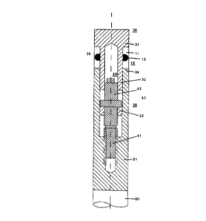
Fig. 3 shows the structure of a piston pressure device
(without cylinder) for use with the sealing device. It
consists of a piston rod 21, a piston 30 (or piston head) and
a means of anchoring 40 for axial attachment of the piston 30
to the piston shaft 20.
The piston shaft 20 comprises a piston rod 21, on whose piston
end 24 there is a hole 22 to hold the piston 30 and a threaded
part 23 for attachment of the means of anchoring 40 (see
below). The inner diameter dKS of the hole 22 is essentially
the same as the outer diameter dKK of the piston base 32. The
threaded part 23 is matched to the thread 41 of the means of
anchoring 40.
The piston 30 comprises a face end 31 and a piston base 32 for
insertion in the hole 22 of the piston shaft 20. The piston
head base 32 has an inner hole 33 to hold part of the means of
anchoring 40 and a radial recess 34 for interworking with a
stop 43 of the anchoring head 42. The stop 43 is formed, for
example, of a radially extending pin whose length is smaller
than the outer diameter dKK of the piston head base 32 and
greater than the diameter dB of the hole 33 in the piston base
32.
The parts of the piston pressure device are assembled so that
the piston 30 with the sealing device and the means of
anchoring 40 are inserted into the hole 22 of the piston shaft
and screwed tight to the threaded part 23 until the sealing
device, especially the elastomer ring 12, is pretensioned, so
that a gas-tight seal is formed in the absence of pressure.
Since the recess 34 of the piston base 32 in axial direction
forms an oblong slot, the piston 30 is mobile in an axial
CA 02283078 1999-08-30
m
direction in relation to the pzston shaft 20. Thus the
compressive force is exercised from the piston rod through the
sealing to the piston head and vice versa from the pressure
medium through the piston tv the piston rod. The pin 43 serves
solely for transmitting torque when screwing in the_piston
head and for engaging the piston head in reverse motion.
The dimensions of the piston 30 and the piston shaft 20 are
chosen so that, with the piston inserted, an annular tee-slot
or recess for the sealing device 10 is formed by the face
section 31 and the piston end of the piston shaft 20 and an
exposed part of the piston base 32. The width of the tee-slot
(spacing between the surface 35 of the face section 31 that
faces the piston shaft and the piston end 24 of the piston
shaft 20) is variable because of the axial mobility of the
piston head 30. Accordingly, When pressure is applied by the
piston head through its motion towards the piston shaft, the
sealing device 10 is compressed to produce the required
sealing function. . _
The functioning of the pressure device according to the
invention is explained with reference to the expanded view of
the piston shaft, sealing device and. piston with the means of
anchoring device in Fig. 4. The piston pressure device
according to the invention (shown without the cylinder)
consists of the piston 30, which is linked to the piston shaft
20 for axial movement by the means of anchoring 40, whereby a
recess for the sealing device 10 is formed between the face
sECtion 31 of the piston 30 and the piston end 24 of the
piston shaft Z0. In an operating state the compressive force
pushes the piston 30 into the hole 22 of the piston shaft 20
at the end of the piston rod 21. Thus the sealing device 10
between the surface 35 of the face section 31, the surface 24
of the piston rod 21, the outer surface of the piston base 32
and the inner wall of try pressure cylinder (not shownl .s
CA 02283078 1999-08-30
12
compressed. This produces a seal all round, whereby
compression of the sealing device occurs essentially without
its direct contact with the pressure medium. At low
compressive force (underpressure or in the normal pressure
range or at slight overpressure) sealing is produced by the
elastic forces of the elastomer ring 12. According to the
invention, these elastic forces are produced by pretensioning
of the sealing device 10 in the recess between piston and
piston shaft. As described above, the pretensioning is set by
screwing in the piston (turning the face section 31 in
relation to the piston shaft 20). This rotation is transmitted
by the pin 43 to the means of anchoring 40 so that it is
screwed by its threaded part 41 into the thread 23 of the
piston shaft 21. This reduces the width of the recess formed
between piston and piston shaft in which the sealing device is
found. The oblong slot 34 extending axially in the piston base
32 enables further reduction of the width of the recess and
thus further compression of the sealing device under the
influence of compressive force. At the same time the pin 43 is
a safeguard against separation of the piston from the piston
shaft in reverse motion.
The piston pressure device according to the invention exhibits
the following advantages. The seal is gas-tight and fluid-
tight. The seal works in wiping fashion through use of the
plastically deformable material under pressure so that no
fluid film forms between the sealing device and the cylinder.
The sealing device is essentially separated from the pressure
medium so that use is possible with random fluid samples. The
piston pressure device can be miniaturized to enable its use
in small, portable high-pressure apparatus. This was not
possible to date because of the complicated mechanical
structure of conventional sealing components. The occlusion of
air or liquid media in the sealing is eliminated so that
filling the high-pressure cylinder and venting it present no
CA 02283078 1999-08-30
13
difficulties. A further advantage is that the means of
anchoring 40, working as a sliding joint, ensures that the
piston is drawn with the piston shaft when pressure is
released. Furthermore, the piston pressure device has no end
play. When pressure is released, the piston structure is
pressed back, the travel of the piston with the pin 43 serving
to overcome frictional forces. The lack of end play is
especially important for reproducible, accurate setting of
very high pressure along through movement of the piston
structure to a predetermined position.
A high-pressure apparatus comprises a piston pressure device
according to the invention, a fluid system and a sample space
or another control element. The fluid system can, according to
the procedure of the invention, be filled in operation of a
piston pressure device under normal pressure or even under
increased pressure. Evacuation of the fluid system or venting
of the sealing is unnecessary. After complete filling, the
fluid system is closed tight and the high-pressure apparatus
can be put into operation.
The sealing according to the invention can be used to
advantage to generate pressure for experiments, technical
processes and for production processes and also for low-
viscosity fluids. This means that the pressure medium in the
pressure vessels and lines can easily be changed or removed
(by allowing remaining fluid to vaporize). In contrast to
conventional pressure devices with "floating" sealings (with
oil film), the invention shows the possibility of stationary
pressure creation without the need for repumping.