Note: Descriptions are shown in the official language in which they were submitted.
CA 02283091 2000-09-O1
UNIVERSAL MOUNTING PLATE FOR
LUMINAIRE FIXTURES
The invention relates generally to universal mounting plates and particularly
to a universal
mounting plate intended for mounting industrial emergency unit fixtures to a
variety of substrates
and support structures.
Luminaire fixtures intended for use in industrial environments take a variety
of
configurations which provide illumination of desirable efficiency and
photometric distributions.
These fixtures must be mounted in a manner which provides for positive and
essentially permanent
placement of the fixtures in desired locations of the industrial environment.
Industrial emergency
unit fixtures, as well as other fixtures, must be mounted in the industrial
environment at particular
locations as normally required by code in order to meet specific safety
requirements. Since such
fixtures must be mounted at particular locations within the industrial
environment, it is essential that
the fixtures be mountable to whatever structure is available at the necessary
mounting locations.
While it is often possible to mount an emergency unit fixture directly to a
wall or to a ceiling, it is
necessary to be able to mount such fixtures to poles, piping, columns,
concrete beams and even
metal framing systems, such as Unistrut frameworks, Unistrut being a trademark
of the Unistrut
Corporation of Houston, Texas. Such mounting must be positive and essentially
permanent for
reasons of safety and further must be amenable to rapid installation without
requirement for
modification of the fixture or of the structure to which the fixture is to be
mounted. Industrial
fixtures and particularly emergency fixtures which typically carry batteries
internally of a fixture
housing can be of substantial weight and therefore must be securely mounted at
heights above the
floor of an industrial environment so that the fixtures can perform intended
functions such as
providing illumination during emergency conditions, power outages and the
like. Such heavy
CA 02283091 2000-09-O1
fixtures mounted above a floor of an environmental space must be positively
held at mounting
locations in order to prevent accidental dislodgment of such fixtures from
mounting locations to
thereby cause an extreme safety hazard.
While luminaire fixtures per se and particularly industrial emergency unit
fixtures cannot be
designed to enable direct mounting to walls, poles, columns and the like
through direct use of fixture
housings per se, it is possible to facilitate mounting of such fixtures by use
of apparatus having so-
called universal mounting application, such mounting apparatus having mounting
holes formed
therein which meet standards of the National Electric Code. In U.S. Patent
4,460,948, Malola
describes an adjustable mounting plate which assists in supporting and
balancing a luminaire fixture
in a desired orientation, the mounting plate being capable of connection to a
variety of luminaire
housings and a variety of supporting structure existing in an industrial
environment. However, the
prior art does not provide a mounting plate structure which can be rapidly
mounted to virtually any
structure existing in an industrial environment and wherein a luminaire
fixture, particularly an
industrial emergency unit fixture, can then be rapidly and positively
connected to the mounting plate
in order to provide positive, safe and reliable mounting of such fixtures at
or in virtually any location
within the industrial environment. Further, the mounting device of the
invention can be mounted to
poles both round and square in section, I-beams, structural columns and the
like as well as flat walls
and even to UNISTRU'>* mounting apparatus of known configuration, the fixture
itself then being
directly mounted to the invention in a manner which is rapidly installable
while assuring safety.
Mounting of a fixture to the mounting device of the invention is accomplished
by the provision of
relatively simple structure on the fixtures per se for engagement of the
fixtures to the mounting
device of the invention, thereby allowing mounting of luminaire fixtures as
aforesaid within an
industrial environment in a manner which is safe, reliable and flexible as to
location due to the
variety of structure to which the invention allows mounting of luminaire
fixtures.
2
* Trade mark
CA 02283091 1999-09-23
The present invention provides a universal mounting device particularly
intended for the
mounting of industrial emergency unit fixtures to essentially any available
structure in an industrial
environment. The universal mounting device essentially takes the form of a
"plate" which can be
mounted to structure within an industrial environment of varying description,
an industrial
emergency unit fixture or other luminaire fixture then being mountable to the
mounting plate of the
invention by means of a simple slide-on connection mechanism which can be
coupled with a snap-
lock mechanism for more effective securement of the fixture in place. The
mounting plate of the
invention is particularly useful for the mounting of emergency unit fixtures
since such features must
be located at particular places within the industrial environment and it is
desirable to be able to
mount such emergency fixtures to any structure available at such locations
without the expense
associated with providing dedicated structure simply for the purpose of
mounting a fixture.
The universal mounting plate of the invention allows mounting of industrial
emergency unit
fixtures as well as other luminaire fixtures in an environment and
particularly an industrial
environment both rapidly and efficiently and with security of mounting so as
to render the mounting
safe for occupants of the environment. The mounting plate allows direct
mounting to a surface such
as a wall surface whether horizontally or vertically oriented, the mounting
plate having a temporary
attachment mechanism in the form of nailing stakes which preliminarily mount
the plate to a suitable
substrate prior to the attachment of the plate to said substrate with screws
or similar connectors. The
mounting plate of the invention is further provided with slots located in
favorable relation to shaped
portions of the plate so as to allow mounting of the plate to poles of both
round and square cross-
section and of varying diameter. Steel banding or the like is utilized in
association with the
mounting plate to fix said plate to said poles or the like prior to connection
of a fixture to the plate.
The mounting plate of the invention can further be mounted to I-beams and to
structural columns of
varying cross-section and size by the same expedient. Still further, the
mounting plate of the
3
CA 02283091 2000-09-O1
invention can be provided with apertures located for mounting to metal framing
systems, such as
Unistrut or similar frameworks, Unistrut being a registered trademark of the
Unistrut Corporation,
Houston, Texas.
On mounting of the mounting plate of the invention to structure within an
industrial
environment, an industrial fixture having spaced openings formed in a housing
thereof is slipped
over bayonet-like projections formed in the mounting plate. A snap-lock
mechanism can further be
provided with a portion of the mechanism being formed integrally with the
mounting plate of the
invention and with the other portion of the snap-lock mechanism being formed
in the housing of the
luminaire fixture so that the fixture is locked in place on engagement of the
bayonet structure of the
mounting plate with corresponding openings of the luminaire housing.
The mounting plate of the invention further provides openings which facilitate
mounting of
J-box structures as well as the pass-through of wiring associated therewith.
The mounting plate thus
permits access of necessary electrical wiring or the like to a luminaire
fixture mounted thereto. The
mounting plate further provides flexibility in design of an environmental
space by virtue of the
ability of the mounting plate to cooperate with a wide variety of commonly
available structures in an
environmental space within which luminaire fixtures and particularly emergency
unit fixtures must
be mounted at particular locations within the envirorunental space, it thus
being possible to minimize
planning and construction of dedicated structure to which such luminaire
fixtures are to be mounted.
The lighting fixtures mounted by the present mounting plate are positively
retained on the
plate, normal vibrations and even seismic activity being incapable of causing
separation between the
fixtures and the plate which is firmly connected to structure within the
industrial environment.
Mounting of the plate to environmental structure further leaves both hands
free for connection of the
fixture to the mounting plate. Use of the miler shown herein allows the plate
to be attachable
without impediments to the hands to further connection of the plate to wall
structure and the like.
4
CA 02283091 1999-09-23
Accordingly, it is a primary object of the invention to provide a universal
mounting device
capable of being rapidly, positively and securely mounted to a variety of
common structure available
in an industrial environmental space, the mounting device being capable of
rapidly and positively
receiving a luminaire fixture such as an industrial emergency unit fixture
onto said device for secure
mounting of said fixture.
It is another object of the invention to provide a mounting plate having
formed integrally
therewith a variety of openings, projections and the like which facilitate
mounting of the plate to
structure within an environmental space and further the mounting of a
luminaire fixture to the
mounting plate itself.
It is a further object of the invention to provide a mounting plate capable of
mounting to
structure as varied as flat walls, poles, I-beams and structural columns and
further being temporarily
stakeable to a flat wall surface prior to the use of screws or other
connectors for more permanent
mounting, the mounting plate on connection to an environmental structure then
allowing the rapid
and positive securement of luminaire fixtures and the like to said mounting
plate.
Further objects and advantages of the invention will become more readily
apparent in light of
the following detailed description of the preferred embodiments.
FIGURE 1 is an exploded perspective view illustrating an emergency unit
fixture arranged in
assembly relation to a universal mounting plate of the invention;
FIGURE 2 is an exploded view of an industrial emergency unit fixture as is
shown in Figure
1 with the mounting plate of the invention in assembly relationship thereto
and as seen from the
other side of the assembly and in relationship to a pole to which the mounting
plate is to be strapped;
FIGURE 3 is a perspective view of another industrial emergency unit fixture as
seen from the
rear thereof and having a universal mounting plate formed according to the
invention shown in an
CA 02283091 1999-09-23
assembled relation thereto, the assembly being shown in an exploded relation
to an I-beam to which
the plate is mounted preferably prior to attachment to the fixture;
FIGURE 4 is a top view of the assembly of Figure 3 shown in relation to a wall
to which the
plate is first connected prior to assembly of the fixture to the plate;
FIGURE 5 is a perspective view of a preferred embodiment of the present
universal
mounting plate;
FIGURE 6 is a front elevational view of the mounting plate of Figure 5;
FIGURE 7 is a side elevational view of the mounting plate of Figure 6;
FIGURE 8 is a front elevational view of the mounting plate of Figure 6;
FIGURE 9 is a sectional view taken along line 9-9 of Figure 6;
FIGURE 10 is a sectional view taken along line 10-10 of Figure 6;
FIGURE 11 is a detail sectional view taken along line 11-11 of Figure 6;
FIGURE 12 is a perspective view illustrating attachment of the mounting plate
of the
invention to a pole by means of strapping;
FIGURE 13 is a top view taken from above the assembly of Figure 12
illustrating contact
between portions of the mounting plate and the pole to which said plate is
attached;
FIGURE 14 is a perspective view illustrating the attachment of the mounting
plate of the
invention to a square post by means of strapping;
FIGURE 15 is a top view taken from above the assembly of Figure 14
illustrating contact
between planar portions of the mounting plate and planar portions of one side
of the square post;
FIGURE 16 is a perspective view illustrating the mounting of a plate devised
according to
the invention to a round post or piping having a diameter of approximately six
inches utilizing
strapping;
FIGURE 17 is a top view taken from above the assembly of Figure 16; and,
6
CA 02283091 2000-09-O1
FIGURE 18 is a perspective view illustrating the use of strapping to hold a
mounting plate to
a structural element by means of strapping and further mounting a lighting
fixture, a portion of the
housing of the lighting fixture being illustrated in the drawing.
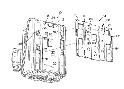
Referring now to the drawings and particularly to Figure 1, a lighting fixture
mountable
according to the present invention is seen generally at 10 to comprise an
industrial emergency unit
fixture, the fixture 10 being mountable at particular locations according to
code and according to
safety considerations at particular locations within an industrial environment
so that emergency
lighting is provided under emergency conditions including failure of mains
electrical power.
Emergency unit fixtures such as the fixture 10 are almost always mounted at a
height within an
industrial space which is greater than eye level. Due to the expense of
mounting emergency fixtures
such as the fixture 10 to structure other than that structure which
incidentally occurs at intended
mounting locations, it is desirable that the fixture 10 be mountable to
virtually any kind of available
structure including wall structure, poles of varying dimension and cross-
sectional shape, structural
columns of varying size and cross-sectional shape, I-beams,
UIVISTRU'I'~frameworks, etc. The
ability to mount fixtures such as the fixture 10 to virtually any structure
available in the
environmental space minimizes the necessity for providing special structure to
which the fixture 10
can be mounted, thereby minimizing costs and reducing the need for special
planning for fixture
mounting capability.
In order to most effectively utilize a universal mounting plate configured
according to the
invention, a portion of a housing 12 of the fixture 10 is configured to be
rapidly and simply
mountable to the fixture 10. The universal mounting plate of the invention is
seen in Figure 1 in
exploded relation to the fixture 10 and is also seen in Figures 2 through l
l,the plate being generally
referred to as the mounting plate 14. While the housing 12 of the fixture 10
can be formed of a
variety of materials, it is particularly convenient to form the housing 12 of
a polymeric material, that
7
* Trade mark
CA 02283091 2000-09-O1
is, a material such as is conventionally referred to as a "plastic" material,
for a variety of reasons. In
particular, a "plastic" material can be formed in the manner of rear face 16
to integrally include
structure which engages and cooperates with the mounting plate 14 to mount
said fixture 10. In
particular, channels 18 are defined on either side of the fixture 10 by
integral, elevated ribs 20 which
are substantially rectangular in cross-section. The ribs not only define the
channels 18 but also
impart additional strength to the housing 12. A major planar surface 22 is
formed centrally of the
rear face 16 of the housing 12 between the elevated ribs 20. An upper portion
of the planar surface
22 has a collar 24 formed therein intended to receive a conduit (not shown)
which can carry
electrical wiring (not shown) into the interior of the fixture 10. A resilient
rectangular tab 26 is
formed congruently with and is movable within a rectangular opening 28 formed
essentially
centrally in the planar surface 22, the tab 26 extending slightly outwardly of
the surface 22 to engage
cooperating structure on the mounting plate 14 to snap-lock the plate 14 to
the fixture 10 as will be
described fi~rther hereinafter.
The channels 18 on the rear face 16 of the fixture 10 are interrupted by pairs
of cross
elements 30 which are integrally formed with the ribs 20 and which have slots
32 formed in lower
side edges of each lowermost cross element 30, the slots 32 communicating with
portions of the
channels 18 which are dimensioned to receive structure of the plate 14 as will
be described
hereinafter.
Referring now to Figure 2, an exploded view is seen with the mounting plate 14
being
disposed in relationship to the rear of the fixture 10 and to a pole 38 shown
to the rear of the
mounting plate 14. Strapping or banding 40, such as steel banding or fabric
banding, is seen to be
wrapped around the pole 38 and pulled through banding slots as can best be
seen in Figure 5 inter
alia. Tool-banding methods as well as other banding or strapping techniques
can be used. The slots
have rounded edges to relieve any stresses on the banding. The mounting plate
14 is thus seen to be
8
CA 02283091 2000-09-O1
mounted to the pole 38 prior to mounting of the fixture 10 to the mounting
plate 14. In essentially
all mounting situations envisioned according to the invention, the mounting
plate 14 is first mounted
to structure within an environmental space, the mounting of the relatively
small and light-weight
mounting plate being extremely easy, the heavier fixture 10 not being dealt
with in an assembly
situation until the mounting plate 14 has been securely mounted to structure
such as the pole 38 of
Figure 2. Banding or strapping is also utilized for mounting of the mounting
plate 12 to structural
columns of varying dimension and cross-sectional shape as well as to
structural I-beams and the like.
Referring to Figure 3, it is to be seen that the mounting plate 14 is usable
with industrial
emergency unit fixtures of differing size, fixture 44 of Figures 3 and 4 being
of a greater size than
the fixture 10 of Figures 1 and 2. The mounting plate 14 is disposed against a
rear face of the fixture
44 in a location as would exist after mounting of the plate 14 to an I-beam
(not shown), for example,
or relative to a wall 48 as seen in Figure 4. Except in unusual circumstances,
the mounting plate 14
will be mounted to an I-beam or the like or the wall 48 prior to attachment of
the fixture 44 to the
mounting plate 14. The rear face 50 of the fixture 44 can be seen to be
configured similarly to the
rear face 16 of the fixture 10 in that ribs 52 define channels 54 having slots
(not shown) which
fiznction in the manner of the slots 32 as described relative to the fixture
10. It is to be understood
that the mounting plate 14 as seen in Figures 3 and 4 would not typically be
mounted to the fixture
44 prior to secure attachment of the mounting plate 14 to structure within an
environmental space
although it is possible to do so. In the assembly of Figure 4, screws 49 or
other fasteners allow
permanent mounting to a wall 48 through appropriate apertures formed in the
plate 14.
Referring now generally to the drawings and particularly to Figures 5 through
11, particular
structure of the mounting plate 14 can be seen and appreciated. The mounting
plate 14 is seen to
comprise a substantially rectangular body 58 having a central channel 60
defined by a U-shaped
central body portion 62 having a substantially flattened yoke portion 64 with
slightly angled leg
9
CA 02283091 2000-09-O1
portions 66 terminating said body portion 62. The yoke portion 64 has an
opening 68 formed
therein, said opening 68 receiving the tab 26 formed on the housing 12 of the
fixture 10 thereinto on
attachment of the fixture 10 to the mounting plate 14, the tab 26 being bent
out of plane within the
opening 28 of the housing 12, the tab 26 then snap-locking into the opening
68. As is seen in Figure
1, the tab 26 is provided with a tab element 70 formed normal to the tab 26
and extending inwardly
of the housing 12 to strengthen said tab 26 and to facilitate manual unlocking
of the locking
mechanism provided by the tab 26 and the opening 68. The snap-locking
mechanism thus described
is only used when a material forming the housing 12 is sufficiently flexible
to allow the flexure
required for sufficient movement to provide snap-locking. It is to be seen
that the larger fixture 44 is
not provided with a tab and opening as is found in the housing 12 of the
fixture 10. The larger
fixture 44 is provided with a threaded aperture (not shown) on the rear face
thereof for receipt of a
threaded fastener such as a screw (not shown) which is received within a
threaded opening 71
formed in the yoke portion 64 of the body portion 62, thereby to allow
fastening of the mounting
plate 14 to the fixture 44.
The angled leg portions 66 of the central body portion 62 each recurve
outwardly to form
lateral planar body potions 72 on each side of the U-shaped central body
portion 62, the planes
within which the lateral planar body portions lie being coincidental with each
other and parallel to
the plane of the yoke portion 64 of the central body portion 62. The lateral
planar body portions 72
have openings formed therein as will be described hereinafter. The lateral
planar body portions 72
each curve out of plane along outer lateral edges thereof to form a U-shaped
rib 74 at each location,
the ribs 74 each recurving outwardly to form outer planar body portions 76
with one each of the
body portions 76 being formed outwardly of each of the body portions 72. The
planes within which
the body portions 76 lie are coincidental with each other and further are
coincidental with the plane
within which the body portions 72 lie. Along lateral edges of each of the
outer planar body portions
CA 02283091 2000-09-O1
76, the mounting plate 14 curves inwardly to form a lateral leg 78 at each end
of the mounting plate
14, the lateral legs each recurving outwardly to form lateral end flanges 80
which effectively
complete the body structure of the mounting plate 14. The mounting plate 14,
along with various
integrally formed structure stamped from the plate 14 and which will be
discussed hereinafter, is
preferably formed of cold-rolled steel of a thickness of approximately 0.1046
inch, that is, 12 gauge
stock, the plate 14 then being powder coated for additional rust resistance.
The mounting plate 14 is
thereby seen to be rapidly and inexpensively manufactured using common
manufacturing techniques
and equipment.
Referring again to Figures 5 through 11 inter alia, the U-shaped central body
portion 62 at
the juncture of the yoke portion 64 and each of the angled leg portions 66 is
formed with four slots
82 with a pair of the slots being formed at one end of the body portion 62 and
the other pair of the
slots being formed at the opposite end thereof. These slots 82 are
particularly useful for receiving
strapping or banding therethrough to connect the mounting plate 14 with a pole
such as the pole 38
as seen in Figure 2, banding also being seen in Figure 2 as shown at 40. In
the event that the pole 38
is of a fairly standard diameter of 4 inches, the central body portion 62
essentially engages the pole
38 on attachment of the mounting plate 14 thereto by means of the banding 40
since the width of the
body portion 62 is essentially 4 inches in dimension. The plate 14 is seen in
Figures 12 and 13 to be
mounted to the pole 38 prior to attachment of a lighting fixture thereto,
lines of contact between the
pole 38 and corners 63 of the plate 14 being seen in Figure 14 due to a
prearranged distance between
the corners 63.
Slots 84 are formed in oppositely facing pairs at upper and lower portions of
the U-shaped
ribs 74 to facilitate the use of banding such as the banding 40 or other
strapping such as steel
strapping for attachment of the mounting plate 14 to structures such as I-
beams, for example, or to
concrete posts, columns, etc.
11
CA 02283091 2000-09-O1
The lateral planar body portions 72 have a series of substantially circular
apertures formed
therein with two pairs of relatively large diameter apertures 86 formed in
upper and lower portions
of the lateral planar body portions 72, these apertures 86 being intended to
receive a bolt portion of a
UNISTRUT*framework or the like. A UNISTRUT*framework is a common mounting
structure
utilizing a spring nut and bolt fitted into a continuously slotted channel,
this structure being a
product of the Unistrut Corportion of Houston, Texas, with Unistrut being a
registered trademark of
that corporation. In such a mounting arrangement, a bolt (not shown) would be
received into the
apertures 86 and then into a threaded nut which is spring mounted within a
slotted channel (not
shown), the bolt, nut, spring and slotted channel being known in the art as a
Unistrut mounting
arrangement.
Threaded apertures 88 formed in a substantially square pattern in the lateral
planar body
portions 72 are intended to facilitate mounting of a J-box (not shown) by
means of threaded
connectors such as screws (not shown) in the event that a J-box structure is
necessary for mounting
to the mounting plate 14. Apertures 90 formed in the lateral planar body
portions 72 between pairs
of the apertures 88 are provided for the pass-through of wiring (not shown)
from a J-box when
utilized.
Each of the outer planar body portions 76 are provided with pairs of openings
92 with two
each of the openings 92 being formed in each of the outer planar body portions
76. The openings 92
are essentially arranged in a rectangular conformation with each of the
openings 92 being essentially
located at a corner of a rectangular pattern so formed. Punched from each
opening 92 is a bayonet
bracket 94 which preferably is formed in a manner, such as by a punching
operation as aforesaid,
which causes the brackets 94 to be formed integrally with the remaining
portions of the mounting
plate 14. Each of the bayonet brackets 94 is effectively L-shaped in section
with free ends 96
extending upwardly. Once the mounting plate 14 is caused to be connected to
structure within an
12
* Trade mark
CA 02283091 1999-09-23
environmental space, such as a pole, wall or the like, a fixture, such as the
fixture 10 or the fixture
44, is brought into engagement with the mounting plate 14 such that the
bayonet brackets 94 are
received into a portion of the channels 18 with the fixture 10 or 44 being
then moved downwardly
relative to the mounting plate so that the free ends 96 of the bayonet
brackets 94 enter the slots 32
formed in the cross-elements 30 of the fixture housings as described above.
Leg portions of the
bayonet brackets 94 then extend through the slots 32 and into the interior of
the fixture housings
until structural portions of the housings defining the slots 32 engage base
portions 98 respectively of
each of the bayonet brackets 94. The fixtures 10 and 44 are thus mounted to
the mounting plate 14
through cooperation of structure formed on rear faces of said fixture housings
and structure,
particularly the bayonet brackets 94, of the mounting plate 14.
When mounting the mounting plate 14 to a wall such as the wall 48 of Figure 4,
temporary
nailing stakes 100 punched from openings 102 formed respectively in each of
the lateral end flanges
80 can be used. The nailing stakes 100 are also seen in Figure 11 to be
punched from material
forming the lateral end flanges 80, free ends 104 of each of the nailing
stakes 100 being bent over to
form a spike-like element which is slightly sharpened in order to facilitate
nailing of the stakes 100
into a wall. In an installation situation whereby the mounting plate 14 is to
be mounted to a wall, the
nailing stakes 100 can be quickly and easily struck with a hammer or the like
to temporarily mount
the plate 14 to the wall such as the wall 48 of Figure 3, the free ends 104 of
the stakes 100
penetrating the wall to provide this temporary mounting. Screws or similar
fasteners can then be
utilized as aforesaid to mount the plate 14 to the wall through apertures 106
formed at respective
ends of the flanges 80 essentially at the corners of the mounting plate 14.
The apertures 106 are not
visible in Figure 4.
Figures 14 and 15 particularly illustrate connection of the mounting plate 14
to a square post
or tube 110 by means of strapping 40. As is best seen in Figure 15, the
distance between corners of
13
CA 02283091 2000-09-O1
the ribs 74 of the plate 14 allows stabilizing contact between planar surfaces
of the plate 14 lying
between the ribs 74 and a flat portion of the square post 110. The square post
110 is therefore
"locked in" to prevent side-to-side movement of the mounting plate 14 relative
to the square post
110.
Figures 16 and 17 illustrate mounting of the mounting plate 14 to a post 112
by means of
banding 40, the post 112 having a greater diameter than does the post 38 of
Figures 12 and 13. The
diameter of the post 112 in Figures 16 and 17 is taken to be approximately six
inches, it being seen
in Figures 17 that the corners 63 continue to provide two points of contact,
or two lines of contact,
between said corners 63 and surfaces of the post I 12. In larger diameter
applications such as Figures
16 and 17, the more outwardly disposed slots 84 can be more conveniently used
in order to further
stabilize mounting of the plate 14 to the post 112.
On mounting of the mounting plate 14 to the post 112, it can be seen in Figure
18, for
example, that a lighting fixture can then be mounted to the mounting plate 14
as is seen in Figure 18,
only a portion of the housing 12 of the fixture being shown for simplicity.
Figure 18 further
illustrates the typical intended use of two of the banding elements 40 in
order to provide a more
stable structure.
From the illustrations given, it is to be seen that poles smaller than three
inches in diameter
can be utilized with two points or lines of contact being retained. Further,
diameters of four to six
inches and larger are easily accommodated through use of the invention with
two lines of contact
being maintained between the mounting plate 14 and exterior surfaces of a
large diameter pole, I-
beam, square concrete pole, etc. Accommodation of round poles to approximately
eight inches in
diameter is particularly reasonable.
Referring again to the bayonet brackets 94 of the mounting plate 14, it is to
be understood
that a rib (not shown) or a pin can be provided lengthwise in said brackets 94
in the event that the
14
CA 02283091 1999-09-23
brackets are not perfectly flat. Mounting of a lighting fixture to the
mounting plate 14 is thus
facilitated.
It is therefore to be seen that the mounting plate 14 can be mounted to
normally available
structure at necessary locations within an environmental space for mounting of
luminaire fixtures
and particularly emergency unit fixtures which must be mounted at particular
locations and normally
at positions elevated above a floor surface of the space preferably without
the need for providing
dedicated mounting structure for such fixtures. The mounting plate 14 of the
invention is configured
to cooperate with structure formed as a part of the housing of such fixtures
so that the mounting plate
14 can be mounted in a desired location followed by mounting of the fixture to
the mounting plate.
While it is preferred to form the mounting plate 14 of the invention from a
unitary piece of material
such as metal or the like, it is possible to form said mounting plate 14 other
than as an integral unit.
Further, while it is preferable to form cooperating structure integrally with
the housing of a fixture
which is to be mounted by the mounting plate 14, it is within the scope of the
invention to form such
cooperating structure other than integrally while remaining within the
intended scope of the
invention. It is further intended according to the invention to provide
structure on the mounting
plate 14 capable of mounting to structure found within an environmental space
other than that
explicitly described herein. Accordingly, the scope of the invention is to be
interpreted in light of
the recitations provided by the appended claims.