Note: Descriptions are shown in the official language in which they were submitted.
CA 02283167 1999-09-10
WO 98/41384 PCT/US98/05067
BONDING A POLYMER MEMBER TO A METALLIC MEMBER
BACKGROUND OF THE INVENTION
This invention generally relates to attachment of high strength polymeric
members to a metallic member and particularly to the attachment of polymeric
tubes
to metallic tubes in intravascular devices such as catheters for use in
percutaneous
transluminal coronary angioplasty (PCTA).
In a typical PTCA procedure a dilatation balloon catheter is advanced over a
guidewire to a desired location within the patient's coronary anatomy where
the
balloon of the dilatation catheter is properly positioned within the stenosis
to be
dilated. The balloon is then inflated to a predetermined size with radiopaque
liquid
at relatively high pressures (generally 4-20 atmospheres) to dilate the
stenosed
region of the diseased artery. One or more inflations may be needed to
effectively
dilate the stenosis. The catheter may then be withdrawn from the stenosis or
advanced further into the patient's coronary anatomy to dilate additional
stenoses.
The inflation pressures used in PTCA procedures have increased considerably
due
to the utilization of high strength balloon materials. However, such higher
pressures
also place substantial stress on other catheter components and particularly
the
junctions between various catheter components. Examples of such components
and junctions are the adapter and the junction with the proximal end of a
metallic
hypotube and the adapter and the distal end of a metallic hypotube and the
polymeric tubular products which form the distal portion of a rapid exchange
type
dilatation catheter. Present manufacturing procedures involve the use of
adhesives,
heat shrinking and the like which limit the materials which can be used and
the
combination of materials which can be used and which complicate the
manufacturing procedure. What has been needed and has heretofore been
heretofore been unavailable is an uncomplicated procedure which produces high
strength, hermetically sealed bonds.
CA 02283167 1999-09-10
WO 98/41384 PCT/US98/05067
2
SUMMARY OF THE INVENTION
The present invention is directed to a system for securely bonding a high
strength polymer material to a metallic member and particularly a small
diameter
tubular polymeric product to a small diameter tubular metallic product.
In accordance with the invention the polymeric member is disposed in contact
with the metallic member, the polymer member is hot pressed against the
metallic
member at a temperature above the glass transition temperature of the
polymeric
material but less than the melting point thereof to effect significant plastic
deformation of the polymeric material. The result is a high strength bond and
a fluid
tight seal which will no leak even under high pressures.
One presently preferred embodiment of the invention is directed to the
bonding of small diameter tubular polymeric members to small diameter tubular
metallic members. A portion of the metallic member is inserted into the inner
lumen
of a polymeric tubular member and a heat shrinkable collar is disposed about
the
portion of the polymeric tubular member into which the metallic member is
disposed.
Heat is applied to the heat shrinkable collar, and the polymeric tubular
member,
causing the collar to shrink and apply sufficient pressure against the
polymeric
tubular member to plastically deform it and thereby bond the polymeric
material to
the surface of the metallic member. The heat shrinkable collar may be left in
place
or removed from the polymeric tubular member after the bond is formed. A
masking
layer may be provided between the collar and the polymeric tubular member to
prevent bonding and facilitate removal of the collar.
Generally, the polymeric material should be a high strength thermoplastic
polymer which is at most semi-crystalline, preferably non-crystalline, and
which is
not ethylenically cross-linked. The preferred polymeric material is an
engineering
polymer such as polyetheretherketone (PEEK), e.g. 581 G sold by Victrex. Other
polymeric materials include polyetheramide sold under the trademark ULTEM by
General Electric, polyphenylene sulfide and polysulfone. The metallic member
may
be stainless steel, such as 304 stainless steel, or a superelastic or
pseudoelastic
NiTi alloy. Other metallic materials may be used such as titanium and alloys
thereof.
There is no special surface preparation needed for the metallic members other
than
removing surface contaminants such as oil, grease and the like.
CA 02283167 1999-09-10
WO 98/41384 PCT/US98/05067
3
One of the advantages of the invention is that the bond is strong enough and
the seal is sound enough so the number of parts needed to construct an
intravascular catheter is reduced considerably. For example, in present
conventional manufacturing practices for rapid exchange type catheters, such
as the
LIFESTREAM Dilatation Catheter sold by Advanced Cardiovascular Systems, Inc.,
up to fve parts are needed to attach a proximal hub or adapter to the proximal
end
of a hypotube shaft. With the present invention the distal end of the adapter
can be
bonded directly to the proximal extremity of a hypotube.
tn addition to a signi5cant reduction in the number of parts, there is no
adhesive used, so there is [sick no requirements for an adhesive curing step
to form
an adhesive bond. The bond of the present invention between the polymeric
material and metallic material is strong, durable and provides a fluid tight
seal
between the joined parts. These and other advantages of the invention will
become
more apparent from the following detailed description and the accompanying
exemplary drawings.
BRIEF DESCRIPTION OF THE DRAWINGS
Fig. 1 is an elevational view, partially in section, of a rapid exchange type
dilatation catheter embodying features of the invention.
Fig. 2 is a transverse cross-sectional view of the catheter shown in Fig. 1
taken along the lines 2-2.
Fig. 3 is a transverse cross-sectional view of the catheter shown in Fig. 1
taken along the lines 3-3
Fig. 4 is a transverse cross-sectional view of the catheter shown in Fig. 1
taken along the lines 4-4.
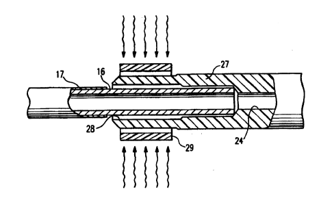
Fig. 5 is an enlarged partial elevational view of a polymeric tubular member
in
position to be hot pressed against the metallic tubular member to facilitate
the
bonding therebetween.
Fig. 6 is a longitudinal cross-sectional view of the members shown in Fig. 5
after the boding procedure.
CA 02283167 1999-09-10
WO 98/41384 PCT/US98/05067
4
DETAILED DESCRIPTION OF THE INVENTION
Figs. 1-5 illustrate a rapid exchange type balloon dilatation catheter 10
which
has an elongated shaft 11 with a dilatation balloon 12 on a distal shaft
section 13 of
the shaft and an adapter 14 on the proximal end of the proximal shaft section
15.
The proximal shaft 15 is formed of a metallic hypotube 16 with a lubricious
coating
17. The distal shaft section 13 includes a distally extending tubular member
18
which has a guidewire receiving inner lumen 20 and which extends through the
interior of the balloon 12 to the port 21 in the distal end of the catheter. A
guidewire
22 is shown disposed within the lumen 20 and extending out the distal port 21
and
the proximal port 23. The inflation lumen 24 is in fluid communication with
the
interior of dilatation balloon 12 through inflation port 25
The distal extremity 26 f the adapter 14 is hot pressed bonded to the proximal
extremity of the proximal shaft section 15 in accordance with the invention. A
high
strength polymeric tubular extension 27 is hot press bonded to the distal
extremity of
the proximal shaft section 15 in the same manner as the distal extremity of
the
adapter is bonded to the proximal extremity of the proximal shaft section. In
both
cases the coating 17 is removed from the exterior of the hypotube 16 to
facilitate
direct bonding to the metallic surface.
Figs. 5 and 6 illustrate a presently preferred method of bonding the polymeric
member, tubular extension 27 to the metallic tubular member 16. As shown in
Fig.
5, the distal end of the metallic tubular member 16 is inserted into the inner
lumen 28
of the tubular extension 27. A heat shrinkable tubular collar 29 is disposed
about
the proximal extremity of the tubular extension 27 and heated to heat shrink
temperatures to press the proximal extremity against the exposed surface of
the
tubular member 16. With the high temperatures and the pressures applied, the
proximal extremity is plastically deformed and is securely bonded to the
metallic
surface. The distal extremity of the adapter 14 is bonded to the proximal
extremity
of the proximal shaft section in essentially the same manner.
EXAMPLE
A stainless steel hypotube with an outer diameter of 0.024 inch (0.6 mm) and
inner diameter of 0.016 inch (0.4 mm) was inserted into the inner lumen of a
~.
CA 02283167 1999-09-10
WO 98/41384 PCT/US98105067
polymeric tubular member form of polyetheretherketone (PEEK). The inner lumen
of
the polymeric tubular member was about 0.026 inch (0.7 mm) and the outer
diameter was about 0.035 inch (0.9 mm). A short piece of a heat shrinkable
tubular
FEP with an outer diameter of about 0.077 inch (2 mm)and an inner diameter of
5 about 0.055 inch (1.4 mm) was disposed about the exterior of the polymeric
tubular
member. The assembly was subjected to an air stream at 450°
F.(232° C.) until the
tubing becomes cloudy. Upon cooling, the FEP tubular collar was removed. The
bond between the PEEK member and the stainless steel member was sound and
leak free at internal pressures of up to fi50 psi.
Although individual features of embodiments of the invention may be shown
in some of the drawings and not in others, those skilled in the art will
recognize that
individual features of one embodiment of the invention can be combined with
any or
all the features of one or more of the other embodiments.