Note: Descriptions are shown in the official language in which they were submitted.
i I ,. n 1 n , I
CA 02283222 2005-04-19
- 1 -
PHOTOCATALYTICALLY-ACTIVATED SELF-CLEANING ARTICLE AND METHOD OF
MAKING SAME
TECHNICAL FIELD
The present invention relates to a method of depositing a
photocatalytically-activated self-cleaning coating on a substrate
(e. g. glass sheet or a continuous glass float ribbon), to a method
of preventing sodium ion poisoning of the photocatalytically-
activated self-cleaning coating deposited over a sodium ion
containing substrate and to articles of manufacture prepared
according to the methods.
BACKGROUND ART
For many substrates (e. g. glass substrates), it is desirable
that the surface of the substrate remain "clean," that is to say
free of surface contaminants, e.g. common organic and inorganic
surface contaminants. Traditionally, this has meant that such
surfaces must be cleaned frequently. This cleaning operation is
typically performed manually or by mechanical devices. Either
approach is quite labor, time and/or cost intensive. A need
exists for substrates having surfaces that are self-cleaning or at
least easier to clean, which would eliminate or reduce the need
for such manual or mechanical cleaning.
CA 02283222 1999-09-10
.-,
~ , 7 7 , O f
- 2 -
Titanium dioxide (Ti02) coatings are known to
provide a photocatalytically-activated self-cleaning
(hereinafter "PASC") surface on a substrate. Publications
directed to the formation of a PASC titanium dioxide coating
on a glass substrate include U.S. Patent No. 5,595,813 and
~~Photooxidative Self-cleaning Transparent Titanium Dioxide
Films on Glass", Paz et al., J. Mater. Res., Vol. 10, No. 11,
pp. 2842-48 (Nov. 1995). Further, a bibliography of patents
and articles relating generally to the photocatalytic
oxidation of organic compounds is reported in Bibliography of
Work On The Photocatalytic Removal of Hazardous Compounds from
Water and Air, D. Blake, National Renewable Energy Laboratory
(May 1994) and in an October 1995 update and an October 1996
update.
A presently available method of applying a PASC
coating (e. g. a titanium dioxide PASC coating) to a substrate
is the sol-gel method. With the sol-gel method an
uncrystallized alcohol-solvent-based colloidal suspension (the
sol) is spray, spin, or dip coated onto a substrate at or
about room temperature. The substrate is then heated to a
temperature within the range of about 100°C to 800°C
(212°F to
1472°F), to either bond the PASC coating to the substrate
and/or to cause the crystallization of the PASO coating, in
order to form a crystallized PASC coating (the gel) on the
substrate.
One limitation of applying a sol-gel PASC coating is
that the sol-gel coating method is not economically or
practically compatible with certain application conditions or
substrates. For example, when it is desired to provide a PASC
coating on a float ribbon during manufacture thereof, the
ribbon may be too hot to accept the sol depending in part, on
the solvent used in the sol solution. For many solvents used
in sol-gel process, it is required to cool the hot float
ribbon to about room temperature before applying the sol, and
to reheat the float ribbon to a temperature sufficient to
crystallize the sol into a PASC coating. Such cooling and
CA 02283222 2005-04-19
- 3 -
reheating operations require a substantial investment in
equipment, energy and handling costs, and significantly decrease
production efficiency.
The PASC activity of PASC coatings may be significantly
reduced or destroyed if sodium ions are present in the substrate
and migrate from the substrate into the PASO coating. This
process is known as sodium poisoning or sodium ion poisoning. For
many substrates which contain sodium ions, the rate of migration
of sodium ions into coatings increases as the temperature of the
substrate increases. Thus another limitation of the sol-gel
coating method is that reheating the substrate increases the
opportunity for sodium ion migration, and in turn, sodium ion
poisoning of a PASC coating.
Another limitation of forming PASC coatings by the sol-gel
method is the thickness of the coatings e.g. several microns (10-6
meters "m") thick. Such thick PASC coatings may have an adverse
affect on the optical and/or aesthetic properties of PASC coated
articles.
As can be appreciated from the foregoing, a need exists for
an article of manufacture having a PASO coating deposited therein
and for a method of depositing a PASC coating that does not suffer
from the drawbacks known in the art.
i .,. a v-n.
CA 02283222 2005-04-19
-4-
DESCRIPTION OF THE INVENTION
The present invention is directed in a first aspect
to a PASO article of manufacture which includes a substrate
having at least one surface and a PASO coating, e.g.,
titanium dioxide, which is deposited over the surface of the
substrate by chemical vapour deposition (hereinafter "CVD"),
or by spray pyrolysis or by magnetron sputtered vacuum
deposition (hereinafter "MSVD"). The present invention in a
second aspect is also directed to a method of making such an
article of manufacture.
The present invention in a third aspect is directed
to a PASC article of manufacture which includes a substrate
having at least one surface, a sodium ion diffusion barrier
(hereafter "SIDB") layer, e.g., tin oxide, titanium dioxide,
aluminum oxide layers and mixtures thereof deposited over
the surface of the substrate, and a PASC coating, e.g., a
titanium dioxide coating deposited over the SIDB layer. The
PASO coating and the SIDB layer are each deposited by a CVD
process or by spray pyrolysis or by a MSVD process. The
present invention in a fourth aspect is also directed to a
method of making such an article of manufacture.
A fifth aspect of the present invention provides a
method comprising the step of manufacturing a continuous
glass float ribbon having a first major surface and an
opposite major surface defined as a second major surface,
the first major surface having tin diffused therein which is
characteristic of forming a glass float ribbon on a molten
tin bath. The next step comprises positioning a chemical
vapour deposition coating apparatus over a surface of the
glass float ribbon at a point in the manufacture of the
glass float ribbon where the glass float ribbon has a
temperature of at least about 400°C.. The next step
comprises directing a metal oxide precursor, namely,
titanium tetrachloride, titanium tetraisopropoxide or
titanium tetraethoxide in a carrier gas stream through the
chemical vapour deposition apparatus over a surface of the
CA 02283222 2005-04-19
-4a-
glass float ribbon. The next step comprises annealing the
glass float ribbon to produce titanium dioxide in the
crystalline phase as a photocatalytically-activated,
self-cleaning coating over the glass float ribbon whereby
said coating has a photocatalytically-activated, self-
cleaning reaction rate of least about 2x10⁻³ cm lmiri 1.
A sixth aspect of the present invention provides a
method comprising the step of manufacturing a continuous
glass float ribbon having a first major surface and an
opposite major surface defined as a second major surface,
the first major surface having tin diffused therein which is
characteristic of forming said glass float ribbon on a
molten tin bath. The next step comprises depositing a
photocatalytically-activated, self-cleaning coating over at
least one of the major surfaces by positioning a spray
pyrolysis coating apparatus over a surface of the glass
float ribbon at a point in the manufacture of the glass
float ribbon where the glass float ribbon has a temperature
of at least about 400°C.. The next step comprises directing
an aqueous suspension of titanyl acetylacetonate and wetting
agent in an aqueous medium, wherein the concentration of the
titanyl acetylacetonate is in the range from about 5 to
about 40 weight percent of the aqueous suspension, through
the spray pyrolysis coating apparatus over a surface of the
glass float ribbon. The next step comprises annealing said
glass float ribbon in air to produce titanium dioxide in the
crystalline phase as a photocatalytically-activated,
self-cleaning coating over said glass float ribbon. The
coating thus has a photocatalytically-activated
self-cleaning reaction rate of at least about 2x10⁻³ cm lmin 1
A seventh aspect of the present invention provides an
improvement in a method for forming a glass float ribbon,
wherein the method comprises the steps of melting glass
batch materials in a furnace to provide molten glass,
delivering the molten glass onto a bath of molten tin,
pulling the molten glass across the tin bath, whereupon the
glass is sized and controllably cooled to form a
CA 02283222 2005-04-19
-4b-
dimensionally-stable glass float ribbon, removing the glass
float ribbon from the tin bath, moving the glass float
ribbon by a conveying roller through a lehr to anneal the
glass float ribbon and moving the glass float ribbon to a
cutting station on conveying rollers where the glass float
ribbon is cut into glass sheets. The improvement comprises,
depositing, by a spray pyrolysis process or a chemical
vapour deposition, a crystalline phase of a
photocatalytically-activated, self-cleaning coating over a
surface of the glass float ribbon as the glass float ribbon
is formed. Such coating has a photocatalytically-activated
self-cleaning reaction rate of at least about 2x10⁻³ cmlminl.
An eighth aspect of the present invention provides a
method comprising the step of providing a glass article
having at least one surface by means of a float
manufacturing process. The next step comprises depositing a
photocatalytically-activated, self-cleaning coating over a
surface of the glass article by a chemical vapour deposition
process or a spray pyrolysis process during the glass
manufacturing process so that the coating has titanium
dioxide in the crystalline phase and has a thickness in the
0
range of at least 200 A and less than 1 micron. Such
coating has a photocatalytically-activated self-cleaning
reaction rate of at least about 2x10⁻³ cm lmiri 1.
A ninth aspect of the present invention provides a
method comprising the step of providing an article of
manufacture having at least one surface. The next step
comprises depositing a sodium ion diffusion barrier layer by
a chemical vapour deposition process, or a magnetron
sputtered vacuum deposition (MSVD) process or a spray
pyrolysis process having a thickness of at least 100 ~ over
the surface. The next step comprises depositing a
photocatalytically-activated, self-cleaning coating by a
chemical vapour deposition process or a MSVD process or a
spray pyrolysis process over the sodium ion diffusion
barrier layer. Such sodium ion diffusion barrier layer
inhibits migration of sodium ions from the surface of the
CA 02283222 2005-04-19
-4C-
article to the photocatalytically-activated, self-cleaning
coating.
A tenth aspect of the present invention provides an
improvement in a method for forming a glass float ribbon
wherein the method comprises the steps of melting glass
batch materials in a furnace to provide molten glass,
delivering the molten glass onto a bath of molten tin,
pulling the molten glass across the tin bath whereupon the
glass is sized and controllably-cooled to form a
dimensionally-stable glass float ribbon, removing the glass
float ribbon from the tin bath, moving the float ribbon by a
conveying roller through a lehr to anneal the glass float
ribbon, moving the glass float ribbon to a cutting station
on conveying rollers where the glass float ribbon is cut
into glass sheets. The improvement comprises depositing, as
the glass float ribbon is formed, a photocatalytically
-activated, self-cleaning coating over the glass float
ribbon which has a major surface and an opposing other major
surface. The major surface which contacted the tin bath has
tin diffused therein so that the deposition is on the major
surface having the diffused tin which forms a sodium ion
barrier layer for the photocatalytically-activated
self-cleaning coating.
An eleventh aspect of the present invention provides a
method comprising the step of manufacturing a continuous
glass float ribbon having a first major surface and an
opposite major surface defined as a second major surface,
the first major surface having tin diffused therein which is
characteristic of forming the glass float ribbon on a molten
tin bath. The next step comprises positioning a chemical
vapour deposition coating apparatus over a surface of the
glass float ribbon at a point in the manufacture of the
glass float ribbon where the glass float ribbon has a
temperature of at least about 400°C.. The next step
comprises directing a metal oxide precursor namely, titanium
tetrachloride, titanium tetraisopropoxide or titanium
tetraethoxide, in a carrier gas stream through the chemical
.., i , 4 ... ,i !P . , i
CA 02283222 2005-04-19
-4d-
vapour deposition apparatus over a surface of the glass
float ribbon. The next step comprises annealing the glass
float ribbon to produce titanium dioxide in the crystalline
phase as a photocatalytically-activatable self-cleaning
coating over the glass float ribbon. Such coating is
capable of having a ghotocatalytically-activated,
self-cleaning reaction rate of least about 2x10⁻³ cm lmin-1.
A twelfth aspect of the present invention provides a
method comprising the step of manufacturing a continuous
glass float ribbon having a first major surface and an
opposite major surface defined as a second major surface,
the first major surface having tin diffused therein which is
characteristic of forming the glass float ribbon on a molten
tin bath. The next step comprises depositing a
photocatalytically-activatable, self-cleaning coating over
at least one of the major surfaces by positioning a spray
pyrolysis coating apparatus over a surface of the glass
float ribbon at a point in the manufacture of the glass
float ribbon where the glass float ribbon has a temperature
of at least about 400°C. The next step comprises directing
an aqueous suspension of titanyl acetylacetonate and a
wetting agent in an aqueous medium, wherein the
concentration of the titanyl acetylacetonate is in the range
from about 5 to about 40 weight percent of the aqueous
suspension, through the spray pyrolysis coating apparatus
over a surface of the glass float ribbon. The next step
comprises annealing the glass float ribbon in air to produce
titanium dioxide in the crystalline phase as a
photocatalytically-activatable, self-cleaning coating over
the glass float ribbon. Such coating is capable of having a
photocatalytically-activated self-cleaning reaction rate of
at least about 2x10⁻³ cm lmiri 1.
A thirteenth aspect of the present invention provides a
method comprising the step of providing a glass article
having at least one surface which is produced by a float
manufacturing process. The next step comprises depositing a
photocatalytically-activatable, self-cleaning coating over a
6 n~ ..t 1~1. .
CA 02283222 2005-04-19
-4e-
surface of the glass article by a chemical vapour deposition
process or a spray pyrolysis process during the glass
manufacturing process so that the coating has titanium
dioxide in the crystalline phase and has a thickness in the
range of at least 200 ~ and less than 1 micron. Such
coating is capable of having a photocatalytically-activated,
self-cleaning reaction rate of at least about 2x10⁻³ cm lmiri 1.
A fourteenth aspect of the present invention provides a
method comprising the step of providing an article of
manufacture having at least one surface. The next step
comprises depositing a sodium ion diffusion barrier layer by
a chemical vapour deposition process, or a magnetron
sputtered vacuum deposition (MSVD) process, or a spray
pyrolysis process having a thickness of at least 100 ~ over
said surface. The next step comprises depositing a
photocatalytically-activatable, self-cleaning coating by a
chemical vapour deposition process, or a MSVD process or a
spray pyrolysis process over the sodium ion diffusion
barrier layer. Such sodium ion diffusion barrier layer
inhibits migration of sodium ions from the surface of the
article to the photocatalytically-activatable, self cleaning
coating.
A fifteenth aspect of the present invention provides ani
improvement in a method for forming a glass float ribbon
wherein the method comprises the steps of melting glass
batch materials in a furnace to provide molten glass,
delivering the molten glass onto a bath of molten tin,
pulling the molten glass across the tin bath whereupon the
glass is sized and controllably-cooled to form a
dimensionally-stable glass float ribbon, removing the glass
float ribbon from the tin bath, moving the glass float
ribbon by a conveying roller through a lehr to anneal the
glass float ribbon and moving the glass float ribbon to a
cutting station on conveying rollers where the glass float
ribbon is out into glass sheets. The improvement comprises
depositing, by a spray pyrolysis process or a chemical
vapour deposition process, a crystalline phase of a
i ", ~~ ~,i~ , . i
CA 02283222 2005-04-19
-4f-
photocatalytically-activatable, self-cleaning coating over a
surface of the glass float ribbon as the glass float ribbon
is formed. Such coating is capable of having a
photocatalytically-activated self-cleaning reaction rate of
at least about 2x103 cm lmiri 1.
A sixteenth aspect of the present invention provides an
improvement in a method for forming a glass float ribbon
wherein the method comprises the steps of melting glass
batch materials in a furnace to provide molten glass,
delivering the molten glass onto a bath of molten tin,
pulling the molten glass across the bath of molten tin,
whereupon the glass is sized and controllably-cooled to form
a dimensionally-stable glass float ribbon, removing the
glass float ribbon from the bath of molten tin, moving the
glass float ribbon by a conveying roller through a lehr to
anneal the glass float ribbon and moving the glass float
ribbon to a cutting station on conveying rollers where the
glass float ribbon is cut into glass sheets. The
improvement comprises depositing, as the glass float ribbon
is formed, a photocatalytically-activatable, self cleaning
coating over the glass float ribbon which has a major
surface and an opposing other major surface. The major
surface which contacted the bath of molten tin has tin
diffused therein so that the depositing is on the major
surface having the diffused tin which forms a sodium ion
barrier layer for the photocatalytically-activatable, self
cleaning coating.
A seventeenth aspect of the present invention provides a
method for forming a glass float ribbon wherein the method
comprises the steps of melting glass batch materials in a
furnace to provide molten glass, delivering the molten glass
onto a bath of molten tin, pulling the molten glass across
the bath of molten tin, whereupon the glass is sized and
controllably-cooled to form a dimensionally-stable glass
float ribbon, removing the glass float ribbon from the bath
of molten tin, moving the glass float ribbon by a conveying
roller through a lehr to anneal the glass float ribbon,
CA 02283222 2005-04-19
-4g-
moving the glass float ribbon to a cutting station on
conveying rollers where the glass float ribbon is cut into
glass sheets. The improvement comprises depositing, by
deposition which is spray pyrolysis or chemical vapour
deposition, a photocatalytically-activated, self-cleaning
coating over a surface of the glass float ribbon at a point
in the manufacture of the glass float ribbon where the glass
float ribbon has a temperature of at least about 400°C.
Such coating has a photocatalytically-activated, self-
cleaning reaction rate of at least about 2x10⁻³ cm lmiri 1.
An eighteenth aspect of the present invention provides a
photocatalytically-activated self-cleaning article of
manufacture. Such article comprises a substrate having at
least one surface and containing sodium. Such article
comprises a photocatalytically-activated, self-cleaning
coating which has been deposited over the surface of the
substrate by a chemical vapour deposition process, magnetron
sputtered vacuum deposition process or spray pyrolysis.
Such coating is at least 100 Angstroms. Such article
comprises a sodium ion poisoning prevention layer which is
either a sodium ion diffusion barrier layer which is
disposed between the substrate and the photocatalytically
-activated, self-cleaning coating with a thickness of at
least about 100 ~1 to inhibit migration of sodium ions from
the substrate to the photocatalytically-activated self
-cleaning coating, or a fraction of the overall thickness of
the photocatalytically-activated self-cleaning coating,
where said photocatalytically-activated, self-cleaning
coating has a thickness that exceeds a minimum thickness so
that the sodium ions are able to migrate only through the
fraction of the overall thickness of the photocatalytically
-activated, self-cleaning coating during any time period at
which the temperature of substrate exceeds the temperature
which permits sodium ion migration. The thickness of the
photocatalytically-activated self-cleaning coating which is
opposite from the substrate surface is able to maintain
photocatalytically-activated self-cleaning coating activity.
CA 02283222 2002-09-20
--4h-
Such photocatalytically-activated, sell-cleaning coating has
a photocatalytically~-activated, self-cleaning reaction rate
of at least about 2x10-~' cm imin-' .
DESCRIPTION OF THE FIGURES
In the accompanying drawings:
Fig. 1 is an elevational view of a portion of a
substrate having a PASC coating dispersed thereon.
Fig. 2 is a view similar to they view of F:ig. 1
illustrating an SIDB layer interposed between the substrate
and the PASC coating.
Fig. 3 is a schematic view of selected components of
a CVD coater,
Fig. 4 is a schematic view of selected components of
a spray pyrolysis coater.
AT LEAST ONE MODE FOR CARRYING OUT THE INVENTION
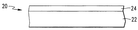
Referring now to Fig. 1, there is shown an article
20 having features of aspects of_ the present invention. The
article 20
CA 02283222 1999-09-10
.~. , ;
. ,
., ,~ , ,
- 5 -
includes a substrate 22 having deposited thereon a PASC
coating 24. The substrate 22 is not limiting to the invention
and may include a glass substrate e.g. a glass sheet or a
continuous glass float ribbon, a plastic substrate, a metal
substrate and an enameled substrate.
The PASC coating 24 may be directly over the
substrate 22 as shown in Figure 1 or in the alternative other
layers may be interposed between the PASC coating 24 and the
substrate 22, e.g. including but not limited to an SIDB layer
26 as shown in Figure 2 and as described in more detail
hereafter. Further, as may be appreciated by those skilled in
the art, the PASC coating 24 may be the uppermost layer of a
multilayer stack of coatings present on substrate 22 or the
PASC coating 24 may be embedded as one of the layers other
than the uppermost layer within such a mufti-layer stack
provided sufficient actinic radiation may pass through any
coatings deposited above PASC coating 24 to photocatalytically
activate PASC coating 24 and provided active radicals can pass
through the coatings deposited above the PASC coating 24 to
react with the organic contaminants present on the uppermost
layer of the multilayer stack.
The PASC coating 24 may be any coating which is
photocatalytically activated to be self-cleaning and which can
be deposited by the CVD method, the spray pyrolysis method or
the MSVD method. For example but not limiting to the
invention, the PASC coating 24 may include one or more metal
oxides such as titanium oxides, iron oxides, silver oxides,
copper oxides, tungsten oxides, aluminum oxides, silicon
oxides, zinc stannates, molybdenum oxides zinc oxides,
zinc/tin oxides, strontium titanate and mixtures thereof. The
metal oxide may include oxides, super-oxides or sub-oxides of
the metal.
A preferred PASC coating 24 is a titanium dioxide
coating. Titanium dioxide exists in an amorphous form and
three crystalline forms, namely the anatase, rutile and
brookite crystalline forms. Anatase phase titanium dioxide, is
CA 02283222 1999-09-10
' ' _ ;
. ) 1
1
~ 1 ~
- 6 -
preferred because it exhibits strong PASC activity while also
possessing excellent resistance to chemical attack and
excellent physical durability. Further, anatase phase
titanium dioxide has high transmission in the visible region
of the spectrum which gives thin coatings of anatase titanium
dioxide with excellent optical properties. The rutile phase
of titanium dioxide also exhibits PASC activity. Combinations
of the anatase and/or rutile phases with the brookite and/or
- amorphous phases are acceptable for the present invention
provided the combination exhibits PASC activity.
The PASC coating 24 must be sufficiently thick so as
to provide an acceptable level of PASC activity. There is no
absolute value which renders the PASC coating 24 "acceptable"
or "unacceptable" because whether a PASC coating has an
acceptable level of PASC activity is largely determined by the
purpose and conditions under which the PASC coated article is
being used and the performance standards selected in
connection with that purpose. In general, thicker PASC
coatings provide higher PASC activity. However, other
considerations may weigh toward a thinner coating, e.g.
thinner coatings are preferred when the article is to have
high transmission for aesthetic or optical reasons; the
surface contaminants on the surface of the article are easily
removed with a thinner PASC coating, the coating is exposed to
substantial irradiation and/or the PASC coating 24 will be
exposed to sodium ion poisoning discussed in more detail
below. For a wide variety of applications, it is preferred
that the PASC coating is at least about 200 Angstroms (A),
preferably at least about 400A and more preferably at least
about 500A thick. It has been found that when the substrate
22 is a piece of float glass and the PASC coating 24 is an
anatase titanium dioxide PASC coating formed directly over the
piece of float glass by the CVD method, that a thickness of at
least about 500A provides a PASC reaction rate in the range of
about 2 x 10⁻³ to about 5 x 10⁻³ per centimer minute
(hereinafter "cm lmin-1") for the removal of a stearic acid test
CA 02283222 2005-04-19
film when the PASC coating was exposed to ultraviolet radiation
from a light source such as that sold under the trade-mark UvA-
340T'"'by the Q-Panel Company of Cleveland, Ohio, having an
intensity of about 20 watts per square meter (hereinafter W/mz) at
the PASC coating surface which is acceptable for a wide range of
applications.
In accordance with aspects of the present invention, a thin
e.g., less than 1 micron (10-6 m), more preferably less than 0.5
micron PASO coating is formed on the substrate 22 by spray
pyrolysis CVD or MSVD methods. In the spray pyrolysis method a
metal-containing precursor is carried either in an aqueous
suspension, e.g. an aqueous solution, and in the CVD method a
carrier gas, e.g. nitrogen gas, and directed toward the surface of
the substrate 22 while the substrate 22 is at a temperature high
enough to cause the metal-containing precursor to decompose and to
form a PASC coating 24 on the substrate 22. In the MSVD method, a
metal-containing cathode target is sputtered under negative
pressure in an inert or oxygen-containing atmosphere to deposit a
sputter coating over substrate 22. The substrate 22 during or
after coating is heated to cause crystallization of the sputter
coating to form the PASC coating 24.
Each of the methods has advantages and limitations e.g. the
CVD method and pyrolysis method are preferred over the spray
pyrolysis method because the aqueous solution of the spray
pyrolysis method may result in the presence of OH- ions in the
PASC coating 24, which may, in turn, inhibit proper crystalline
formation in the PASC coating 24 thereby reducing the PASC
activity of the coating. The CVD method and pyrolysis method are
preferred over the MSVD method because it is compatible with
coating continuous substrates found at elevated temperatures e.g.
glass float ribbons. The CVD, spray pyrolysis and MSVD methods of
depositing PASC coating 24 are discussed in more detail below. As
may be appreciated, spray pyrolysis and CVD methods may be used to
deposit thin (e. g., a few hundred Angstrom thick) metal oxide
coatings
CA 02283222 2002-09-20
-g.._
(including titanium dioxide coatings) aver a substrate.
Such coatings are described in LT. S. Patent Nos. 4,344,986
issued August 17, 1982 to Henery; 4,393,095 issued July 12,
1.983 to Greenberg; 4, 400, 412 issued A~.zgust: 23, 1983 to
Scanlon et al.; 4,719,126 issued Janua:x:y 1.2, 1988 to Henery;
4,853,257 issued August 1, 1989 to Henery; and 4,971,843
issued November 20, 1990 to Michelotti et al.
Metal-containing precursors that: may be used in the
practice of aspects of the present invention to form
titanium dioxide PASC coatings by the CVD method include,
but are not limited to, titanium tetrac::hloride (TiCl4) ,
titanium tetraisopropoxide (Ti(OC3H,)~,) (he.reinafter "TTIP")
and titanium tetraethoxide (Ti (OC>H5) .~) (hereinafter "TTEt") .
Carrier gases that may be used in the CVD method include,
but are not limited t:o, air, ,nitrogen, oxygen, ammonia and
mixtures thereof. The preferred carrier gas is nitrogen and
the preferred metal-containing precursor is TTIP. The
concentration of the metal-containing precursor in the
carrier gas is generally in the range of 0.1% to 0.4% by
volume for the three listed metal-containing precursors, but
as may be appreciated by those skilled in the art, these
concentrations may be varied for other metal-containing
precursors.
Metal-containing precursors that may be used in the
practice of aspects of the invention to form PASO coatings
by the spray pyrolysis method include relatively water
insoluble organometallic reactants, specifically metal
acetylacetone compounds, which are jet milled or wet ground
to a particle size of less thC~n about 10 macrons (10-'' m) and
suspended in an aqueous medium by the use 4~f a chemical
wetting agent. A suitable metal acetylacetonate to form a
titanium dioxide PASO coating is titanyl ac:etylacetonate
('ri0 (C;H~02) 2) . The relative conc~entrati.on of the metal
acetylacetonate in the aqueous suspension preferably ranges
from about 5 to 40 weight percent of tile aqueous suspension.
The wetting agent may be a.ny relatively low foaming
surfactant, including anionic, nonionic or cationic
CA 02283222 2002-09-20
~8a-
compositions, although nonionic is preferred. The wetting
agent is typically added at about 0.24 by° weight, but can
range from about 0.01% to 1% or more. The aqueous medium is
preferably distilled or deionized water. Aqueous
.. ~ . 4 .~. .i ! n. .. . . . ,
CA 02283222 2005-04-19
- 9 -
suspensions for pyrolytic deposition of metal-containing films are
described in U.S. Patent No. 4,719,127 issued January 12, 1988 to
Greenberg particularly at column 2, line 16, to column 4, line 48.
For both the CVD and the spray pyrolysis methods, the
temperature of the substrate 22 during formation of the PASC
coating 24 thereon must be within the range which will cause the
metal containing precursor to decompose and form a coating having
PASC activity (e. g. crystalline phase for metal oxide PASC
coatings). As may be appreciated, the lower limit of this
temperature range is largely affected by the decomposition
temperature of the selected metal-containing precursor. For the
above listed titanium-containing precursors, the minimum
temperature of substrate 22 which will provide sufficient
decomposition of the precursor is within the temperature range of
about 400°C (752°F), about 500°C (932°F). The
upper limit of this
temperature range may be affected by the substrate being coated.
For example where the substrate 22 is a glass float ribbon and the
PASC coating 24 is applied to the float ribbon during manufacture
of the float ribbon, the float glass may reach temperatures in
excess of 1000°C (1832°F). The float glass ribbon is usually
attenuated or sized (e. g, stretched or compressed) at temperature
above 800°C (1472°F). If the PASC coating 24 is applied while
the
float glass before or during attenuation, the PASO coating 24 may
crack or crinkle as the float ribbon is stretched or compressed
respectively. Therefore, in the practice of the invention it is
preferred to apply the PASO coating when the float ribbon is
dimensionally stable e.g, below about 800°C (1472°F) for soda
lime
silica glass, and the float ribbon is at a temperature to
decompose the metal-containing precursor e.g. above about 400°C
(752°F) .
Forming PASC coating 24 by CVD or spray pyrolysis methods is
particularly well suited for practice during the manufacture of
3S the glass float ribbon. In general, a glass
i ~ v ~. .
CA 02283222 2005-04-19
-10-
float ribbon is manufactured by melting glass batch
materials in a furnace and delivering the refined molten
glass onto a bath of molten tin. The molten glass on the
bath of molten tin is pulled across the bath of molten tin
as a continuous glass ribbon while it is sized and
controllably-cooled to form a dimensionally-stable glass
float ribbon. The glass float ribbon is removed from the
bath of molten tin and moved by conveying rolls through a
lehr to anneal the glass float ribbon. The annealed glass
float ribbon is then moved through cutting stations on
conveyor rolls where the glass float ribbon is cut into
glass sheets of desired length and width. U.S. Patent Nos.
4,466,562 issued August 21, 1984 to De Torre and 4,671,155
issued June 9, 1987 to Goldinger provide a discussion of the
float glass process.
Temperatures of the glass float ribbon on the bath
of molten tin generally range from about 1093.3°C at the
delivery end of the bath to about 538°C at the exit end of
the bath. The temperature of the float ribbon between the
tin bath and the annealing lehr is generally in the range of
about 480°C to about 580°C; the temperature of the glass
float ribbon in the annealing lehr generally ranges from
about 204°C to about 557°C peak.
U.S. Patent Nos. 4,853,257 issued August 1, 1989 to
Henery; 4,971,843 issued November 20, 1990 to Michelotti et
al,; 5,464,657 issued November 7, 1995 to Athey et al.; and
5,599,387 issued February 4, 1997 to Neuman et al. describe
CVD coating apparatus and methods that may be used in the
practice of aspects of this invention to coat the glass
float ribbon during manufacture thereof. Because the CVD
method can coat a moving glass float ribbon yet withstand
the harsh environments associated with manufacturing the
float ribbon, the CVD method is well suited to provide the
PASC coating 24 on the glass float ribbon. The CVD coating
apparatus may be employed at several points in the glass
float ribbon manufacturing process. For example, CVD
coating apparatus may be employed as the glass float ribbon
CA 02283222 2002-09-20
-11-
travels through the bath of molten tin after it exits the
bath of molten tin, before it enters the annealing lehr, as
it travels through the annealing lehr, or after it exits the
annealing lehr.
As may be appreciated by those skilled in the art,
concentration of the metal-containing precursor in the
carrier gas, the rate of flow of the carrier gas, the speed
of the float ribbon (the "line speed"), the surface area of
the CVD coating apparatus relative to the surface area of
the float ribbon, the surface areas and rate of flow of
exhausted carrier gas through exhaust vents of the CVD
coating apparatus more particularly, the ratio of exhaust
rate through the exhaust vents versus the carrier gas input
rate through the CVD coating unit, known as the "exhaust
matching ratio" and the temperature of the float ribbon are
among the parameters which will affect the final thickness
and morphology of the PASO coating 24 formed on float ribbon
by the CVD process.
U.S. Paten.t Nos. 4,719,7..26 issued ~lanuary 12, 1988
to Henery; 4,719,127 issued January 12, 1988 to Greenberg;
4,111,150 issued September 5, 1978 to Donley et al.; and
3,660,061 issued May 2, 1972 t:o Donley et r~l. describe spray
pyrolysis apparatus and methods that may bk.=. used with the
float ribbon manufacturing process. while the spray
pyrolysis method like the CVD method is well suited for
coating a moving float glass ribbon, the spray pyrolysis has
more complex equipment than the CVD equipment and is usually
employed between the exit end of the bath of molten tin and
the entrance end of the annealing lehr.
As can be appreciated by those skilled in the art,
the constituents and concentration of t:he ~;~yrolytically
sprayed aqueous suspension, the line speed of the float
ribbon, the number of pyrolytic spray guns, the spray
pressure or volume, the spray pattern, and the temperature
oi= the float ribbon at the tithe of deposition are among the
parameters which will affect the final thickness and
morphology of the PASC coating 24 formed on the float ribbon
CA 02283222 2002-09-20
_. 12 __
by spray pyrolysis.
As is known by those skilled in the art, the surface
of the glass float ribbon on the molten tin (commonly
referred to as the "tin side") has diffused tin in the
surface which provides the tin side with a pattern of tin
absorption that is different from the opposing surface which
is not in contact with the molten tin (commonly referred to
as "the air side"). This characteristic i.s discussed in
Chemical Characteristics of Float Glass Surfaces, Seiger,
J., JOURNAL OF NON-CRYSTALLINE SOLIDS, Vol. 19, pp. 213-220
(1975); Penetration of Tin in The Bottom Surface of Float
Glass: A Synthesis, Columbin L. et al., JOURNAL OF NON-
CRYSTALLINE SOLIDS, Vol. 38 & 39, pp. 551-556 (1980); and
Tin Oxidation State, Depth Profiles of Sn''' and Sn'a and
Oxygen Diffusivity in Float Glass by Mossbauer Spectroscopy,
Williams, K.F.E. et al., JOURNAL OF NON-CRYSTALLINE SOLIDS,
Vol. 211, pp. 164-172 (1997). As may be appreciated by
those skilled in the art, the PASO coating 24 may be formed
on the air side of the float ribbon while :it is supported on
the tin bath (by the CVD method); on the air side of the
float ribbon after it leaves the tin bath by either the CVD
or spray pyrolysis methods and on the tin ride of the float
ribbon after it exits the tin bath by the CVD method. When
the PASO coating 24 is formed on the tin side of float
ribbon, it is expected that tree tin and/or tin oxide present
in glass surface will function as an SIDB layer 26 for the
PASC coating 24 disposed thereon.
U.S. Patent Nos. 4,379,040 issued April 5, 1983 to
G=illery; 4, 861, 669 issued August 29, 1989 2::o Gillery;
4,900,633 issued February 13, 1990 to Gillery; 4,920,006
issued April 24, 1990 to Gillery; 4,938,857 issued July 3,
1990 to Gillery; 5,328,768 issued July 12, 1994 to Goodwin;
and 5,492,750 issued February 20, 1996 to Shumaker, Jr. et
al describe MSVD apparatus and methods to sputter coat metal
oxide films on a substrate, including a glass substrate.
The MSVD process is not generally compatible with providing
a PASC coating over a glass float ribbon during its
CA 02283222 2002-09-20
-12a-
manufacture because, among other things, the MSVD process
requires negative pressure during the sputtering operation
which is difficult to farm over a cont:inuausly-moving float
ribbon. However, the MSVD method is acceptable to deposit
the PASC coating 24 on substrate 22, e.g., a glass sheet.
As can be appreciated by those skilled in the art, the
substrate 22 may be heated to temperata.xres in the range of
about 400°C to about 500°C so that the MSVD sputtered coating
on the substrate crystallizes during deposition process,
thereby eliminating a subsequent: heatit-.~g operation. Heating
the substrate during sputtering is not a preferred method
because the additional heating operation during
CA 02283222 1999-09-10
.' . " . ~ ~ , ~. "
~ l ' 9 ' 1 9
- 13 -
sputtering may decrease throughput. Alternatively the sputter
coating may be crystallized within the MSVD coating apparatus
directly and without post heat treatment by using a high
energy plasma, but again because of its tendency to reduce
throughput through an MSVD coater, this is not a preferred
method.
The preferred method to provide a PASC coating using
the MSVD method is to sputter a coating on the substrate,
remove the coated substrate from the MSVD coater and
thereafter heat treat the coated substrate to crystallize the
sputter coating into the PASC coating 24. For example, but
not limiting to the invention, with the MSVD method, a target
of titanium metal sputtered in an argon/oxygen atmosphere
having about S-50s, preferably about 20°s oxygen, at a pressure
of about 5-10 millitorr (0.67 to 1.33 Pascals) to sputter
deposit a titanium dioxide coating of desired thickness on the
substrate 22. The coating as deposited is not crystallized.
The coated substrate is removed from the coater and heated to
a temperature in the range of about 400°C (752°F) to about
600°C (1112°F) for a time period sufficient to promote
formation of the PASC crystalline form of titanium dioxide to
render PASC activity. Generally at least an hour at
temperature in the range of about 400°C (752°F) to about
600°C
(1112°F) is preferred. Where the substrate 22 is a glass sheet
cut from a glass float ribbon, the PASC coating 24 may be
sputter deposited on the air side and/or the tin side.
The substrate 22 having the PASC coating 24
deposited by the CVD, spray pyrolysis or MSVD methods may be
subsequently subjected to one or more post-PASC coating
annealing operations to increase the self-cleaning activity of
the PASC coating 24. It is believed that such post-PASC
coating annealing may increase self-cleaning activity of the
PASC coating 24 by promoting formation of the desired PASC
crystalline phase. As may be appreciated, the time and
temperatures of the anneal may be affected by several factors,
including the makeup of substrate 22, the makeup of PASC
CA 02283222 1999-09-10
1 9 ~ ~ ' 1
1 1 1 0 O 1 ,
- 14 -
coating 24, the thickness of the PASC coating 24, and whether
the PASC coating 24 is directly on the substrate 22 or is one
layer of a multilayer stack on substrate 22. It has been
determined that where the substrate 22 is a piece of float
glass and the PASC coating is a 400A or 625A thick anatase
titanium dioxide formed by the spray pyrolysis method, that
annealing the coating at 500°C (932°F) for up to 13 minutes
increased PASC activity.
As discussed above, whether the PASC coating is
provided by the CVD process, the spray pyrolysis process or
the MSVD process, where the substrate 22 includes sodium ions
that can migrate from substrate 22 into the PASC coating
deposited on substrate 22, the sodium ions may inhibit or
destroy the photocatalytic activity of the PASC coating by
forming inactive compounds while consuming titanium e.g. by
forming sodium titanates or by causing recombination of
photoexcited charges.
It has been found that the PASC coating may be
formed over a sodium ion containing substrate 22 without loss
of photocatalytic activity by: 1) providing for a limited
partial sodium ion poisoning of a portion of the PASC coating;
and/or 2) providing an SIDB layer 26. Each method is
discussed in detail below.
It has been found that when the thickness of the
PASC coating exceeds a minimum threshold value, the PASC
activity is not destroyed by sodium ion migration even though
the PASC coating is deposited over the surface of a sodium-ion
containing substrate while the substrate is at a temperature
sufficient to cause migration of sodium ions from substrate
into the PASC coating. While the mechanism for this result is
not completely understood, it is believed that when the
thickness of the PASC coating exceeds this minimum thickness,
the sodium ions are able to migrate only through a fraction of
the overall thickness of the PASC coating during the time
period at which the temperature of substrate exceeds the
temperature which permits sodium ion migration. Thereafter,
CA 02283222 1999-09-10
,,,'
1 j o 1 )
v1 y 1 7 t m
- 15 -
when the temperature of substrate falls below that which
causes sodium ion migration, the sodium ions migration stops
or "freezes" in place, resulting in a thickness of the PASC
coating opposite from the substrate surface free of sodium ion
poisoning and able to maintain PASC activity. This minimum .
thickness of the PASC coating as may be appreciated by those
skilled in the art varies with expected parameters such as,
but not limited to, the time at which substrate is held above
the temperature at which sodium ion migration occurs, the use
to which the PASC article of manufacture is to be put and the
degree of PASC activity desired or required. It has been
found that for a CVD deposited titanium dioxide PASC coating
over a piece of soda-lime-silica flat glass, the thickness of
the PASC coating should be a minimum of about 250A, preferably
a minimum of about 400A and more preferably a minimum of about
500A to permit a sufficient portion of the PASC coating 24 to
remain free of sodium ion poisoning and retain its PASC
activity.
Referring now to Fig. 2, in an alternative method of
preventing sodium ion poisoning of the PASC coating, an SIDB
layer 26 is provided between the PASC coating 24 and the
substrate 22. The SIDB layer 26 may be the only layer between
the PASC coating 24 and the substrate 22, or it may be one
layer of a multilayer stack. Where a multilayer stack is
employed, it is not required that the SIDB layer 26 be in
contact with the substrate 22, provided the SIDB layer 26 is
positioned between the PASC coating 24 and the substrate 22 to
prevent sodium ion migration from the substrate 22 to the PASC
coating 24.
The SIDB layer 26 may be formed of amorphous or
crystalline metal oxides including but not limited to cobalt
oxides, chromium oxides and iron oxides, tin oxides, silicon
oxides, titanium oxides, zirconium oxides, fluorine-doped tin
oxides, aluminum oxides, magnesium oxides, zinc oxides, and
mixtures thereof. Mixtures include but are not limited to
magnesium/aluminum oxides and zinc/tin oxides. As can be
,., i " , c ~, .,
CA 02283222 2005-04-19
- 16 -
appreciated by those skilled in the art, the metal oxide may
include oxides, super-oxides or sub-oxides of the metal. While
the thickness of the SIDB layer necessary to prevent sodium ion
poisoning of the PASC coating varies with several factors
including the time period at which a substrate will be maintained
at temperatures above which sodium ion migration occurs, the rate
of sodium ion migration from the substrate, the rate of sodium ion
migration through the SIDB layer, the thickness of the PASC
coating and the degree of photocatalytic activity required for a
given application, typically for most applications, the SIDB layer
thickness should be in the range of at least about 100.x,
preferably at least about 250Pr and more preferably at least about
500 thick to prevent sodium ion poisoning of the PASO coating
layer. The SIDB layer may be deposited over substrate 22 by CVD,
spray pyrolysis, or MSVD methods. Where the spray pyrolysis or
CVD methods are employed, the substrate 22 is preferably
maintained at a temperature of at least about 400°C (752°F) to
ensure decomposition of the metal-containing precursor to form the
SIDB layer. The SIDB layer may be formed by other methods,
including the sol-gel method, which sol-gel method as noted above
is not compatible with the manufacture of a glass float ribbon.
A tin oxide SIDB layer may be deposited on substrate by
spray pyrolysis by forming an aqueous suspension of dibutyltin
difluoride (C4H9)ZSnF2 and water and applying the aqueous
suspension to the substrate via spray pyrolysis. In general, the
aqueous suspension typically contains between 100 to 400 grams of
dibutyltin difluoride per liter of water. Wetting agents may be
used as suspension enhancers. During the preparation of the
aqueous suspension, the dibutyltin difluoride particles may be
milled to an average particle size of 1 to 10 microns (10-6m). The
aqueous suspension is preferably vigorously agitated to provide a
uniform distribution of particles in suspension. The aqueous
suspension is delivered by spray pyrolysis to the surface of a
i " a ,. ., ,
CA 02283222 2005-04-19
- 17 -
substrate which is at a temperature of at least about 400°C
(752°F), preferably about 500°C to 700°C (932°F to
1292°F)
whereupon the aqueous suspension pyrolyzes to form a tin oxide
SIDB layer. As may be appreciated, the thickness of SIDB layer
formed by this process may be controlled by, among other
parameters, the coating line speed, the dibutyltin difluoride
concentration in the aqueous suspension and the rate of spraying.
Alternatively the tin oxide SIDB layer may be formed by the
CVD method on the substrate from a metal-containing precursor such
as a monobutyltintrichloride vapor (hereinafter "MBTTCL") in an
air carrier gas mixed with water vapor. The MBTTCL vapor may be
present in a concentration of at least about 0.5% in the air
carrier gas applied over substrate while the substrate is at a
temperature sufficient to cause the deposition of a tin containing
layer e.g. at least about 400°C (952°F), preferably about
500°C to
800°C (932°F to 1472°F) to form the tin oxide SIDB layer.
As may
be appreciated the thickness of the SIDB layer formed by this
process may be controlled by, among other parameters, the coating
line speed, the concentration of MBTTCL vapor in the air carrier
gas and the rate of carrier gas flow.
An SIDB layer formed by the MSVD process is now known.
Alkali metal diffusion barrier layers are generally effective at
thicknesses of about 20 to about 180A, with effectiveness
increasing as the density of the barrier increases.
The PASC coatings of aspects of the present invention are
usually photocatalytically-activated to self-cleaning upon
exposure to radiation in the ultraviolet range, e.g., 300-400
nanometers (hereinafter "nm") of the electromagnetic spectrum.
Sources of ultraviolet radiation include natural sources e.g.
solar radiation and artificial sources, e.g., a black light
CA 02283222 1999-09-10
_ ,~
, . . x . : , ,
s a
' a s s . . . ' ~ s s
s ~ s . v
. -, r s s x ~ ' v v
- 18 -
or an ultraviolet light source such as the UVA-340 light
source. When using artificial ultraviolet light sources under
testing conditions where it is desired to determine how the
PASC coating will react the natural ultraviolet radiation, as
may be appreciated, the UVA-340 light source has a photon
energy distribution which more closely matches that of
sunlight than does the photon energy distribution of a black
light source, allowing the UVA-340 light source to be used to
more closely approximate how the PASC coating performs when
exposed to sunlight.
The ultraviolet radiation intensity is calibrated to
an intensity of at least about 20 watts per square meter
(hereinafter "W/mz") at the coated surface of the coating being
tested. The intensity may be calibrated, for example, with an
ultraviolet meter such as that sold under the trademark BLACK-
RAY~ by Ultraviolet Products, Inc., of San Gabriel, CA, under
the model designation J-221. The light source is preferably
positioned normal to the coating surface being tested.
The ultraviolet radiation source and the PASC
coating may be positioned relative to each other such that the
ultraviolet radiation passes first through the PASC coating
then through the substrate (i.e. the front or "coating side").
Where the substrate passes ultraviolet radiation therethrough,
the PASC coating and the ultraviolet radiation source may be
positioned relative to each other such that the ultraviolet
radiation passes first through the substrate and then through
the PASC coating (i.e. the back or "substrate side"). In
still another embodiment, one or more ultraviolet radiation
source may be positioned on each side of the substrate having
a PASC coating on one or both of the surfaces.
As may be appreciated, it is difficult to define
with specificity a preferred ultraviolet radiation source or
ultraviolet radiation intensity or ultraviolet radiation
source/PASC coating/substrate relative positioning because
many factors affect such considerations. These factors
include, among others: the purpose for which the PASO coating
CA 02283222 1999-09-10
~ . ...
' , j > >
~. 7 .1 ~ ) 9
- 19 -
is employed e.g. indoor or outdoor use; the selected
ultraviolet radiation source e.g. natural or artificial;
seasonal or geographic effects where the ultraviolet radiation
source is natural; the desired or expected duration of
ultraviolet radiation exposure; the incident angle of the
ultraviolet radiation with the surface of the PASC coating;
the rate of PASC activity expected or desired; the degree to
which the ultraviolet radiation may be reflected or absorbed
by the substrate and/or any other coatings or layers present
over the substrate or over PASC coating; the contaminants
sought to be removed; the thickness of the PASC coating; the
composition of the PASC coating; the potential for sodium ion
poisoning; and the presence or absence of an SIDB layer.
However, it has been found that an ultraviolet radiation
intensity within the range of about 5 to 100 W/mz, preferably
at least about 20 W/m2, as measured at the surface of PASC
coating from an ultraviolet radiation source positioned over
the surface of the PASO coating will produce sufficient
intensity to cause satisfactory PASC activity for many self-
cleaning applications.
It is useful to be able to measure and compare the
PASC effectiveness or activity of PASC coatings in order to
evaluate the PASC activity of a PASC coating. A known,
readily available organic contaminant may be applied over the
PASC coating, and upon photocatalytically activating the PASC
coating, the ability of the PASC coating to remove the organic
contaminant may be observed and measured. Stearic acid,
CH3(CHZ)isC00H, is a model organic "contaminant" to test the
PASC activity of PASC coatings, because stearic acid is a
carboxylic acid with a long hydrocarbon chain and is therefore
a good "model molecule" for those present in common
contaminants such as household oils and dirt. The stearic
acid may be applied over the PASC coating as a thin test film
by any convenient technique including dipping, spraying, spin
coating. Generally stearic acid test films ranging from about
100A to about 200A thick provide an adequate test film. The
CA 02283222 1999-09-10
, ..,. ,
1 1
~ a y ~ ro r r
v , ~ ~ 1 r
~ , , r r
~e r i ~ ~
- 20 -
stearic acid may be applied as a stearic acid in methanol
solution and a solution having a concentration of about 6 x
10-3 moles of stearic acid per liter of solution has been found
to be satisfactory.
The PASC activity of PASC coatings may be estimated
qualitatively by overcoating PASC coating with a stearic acid
film (the film generally appears as a light brown coating when
applied over the PASC coating) exposing the stearic acid film
to ultraviolet radiation at a desired intensity for a desired
interval, and examining the stearic acid film with the unaided
eye for either the complete disappearance of the stearic acid
test film or for a decrease in the darkness of the stearic
acid film in comparison to a portion of.the stearic acid film
applied over the PASC coating but not exposed to ultraviolet
radiation.
The PASC activity of PASC coatings may also be
measured quantitatively by measuring the integrated intensity
of the carbon-hydrogen (hereinafter "C-H") stretching
vibrational absorption bands of the stearic acid present on
the PASC coating. The integrated intensity is commensurate
with the thickness of stearic acid film remaining on the
surface of the PASC coating, and removal of the stearic acid
film by photocatalytically-activated self-cleaning is expected
to result in a drop in the C-H stretching vibrational band
intensity. The C-H bonds present in the stearic acid absorb
infrared radiation which unlike ultraviolet radiation, does
not photocatalytically activate the PASC coating. This
absorption generally occurs between 2800 and 3000 cm 1 wave
numbers, and may be measured with a Fourier Transform Infrared
Spectrophotometer (hereinafter "FTIR Spectrophotometer"). The
FTIR may be equipped with a detector such as a deuterated
triglycine sulface detector (hereinafter "DTGS detector") or a
mercury-cadmium-telluride detector (hereinafter "MCT
detector"). The MCT detector is preferred as it provides a
much higher signal-to-noise ratio than the DTGS detector.
This can be important where the substrate and/or other
CA 02283222 1999-09-10
~ ' , . i v s
t . ~ y s v
' ~ 7 1 ~ 1 f 1 9 ~ ~
- 21 -
coatings in addition to the PASC coating to absorb the
infrared radiation which is used by the spectrophotometer to
generate the absorption spectrum. When the infrared radiation
is absorbed by the substrate and/or other coatings, the
intensity of the infrared radiation beam that passes through'
the stearic acid film, PASC coated, and substrate to the
detector is significantly reduced. Combining this with the
low concentration of stearic acid present on the surface of
the PASC coating (which produces a very weak infrared
radiation absorption feature) and the resultant infrared
radiation signal is not particularly intense. Therefore, an
instrument equipped with the MCT detector provides a spectrum
in which the signal-to-noise ratio is about an order of
magnitude higher than those equipped with DTGS detectors.
When measuring the PASC activity of a stearic acid test film
deposited over films and substrates through which the infrared
radiation beam may pass, the infrared radiation beam may be
directed through the films and substrate onto the detector
positioned on the opposite side of the sample being tested.
Where the films or substrates will not permit the passage of
infrared radiation therethrough, the infrared radiation beam
may be directed at an angle over the surface, passing through
the stearic acid test film and reflecting off of the substrate
as opposed to passing therethrough onto the detector. This
latter method is known as reflection IR spectroscopy.
A PASC reaction rate may be determined for a PASC
coating by measuring the rate at which the PASC coating reacts
to remove the stearic acid film thereon when the PASC coating
is exposed to actinic radiation. More particularly, the rate
of decrease in the integrated intensity of the C-H stretching
vibrational feature (directly proportional to surface
coverage) with accumulated time of exposure to actinic
(hereafter assumed to be ultraviolet) radiation provides the
PASC reaction rate. For example, an initial PASC activity is
measured with the FTIR spectrophotometer for a stearic acid
test film present on a PASC coating. The PASC coating may or
CA 02283222 1999-09-10
' 7 7 ' 9 1
, , ' '
' ) 3 9 W ) i
- 22 -
may not have been exposed to ultraviolet radiation for this
initial PASC activity measurement. The stearic acid coated
PASC coating is then exposed to ultraviolet radiation for a
measured interval of time, at the end of which a second PASC
S activity measurement is made with the FTIR spectrophotometer.
The integrated intensities of the C-H stretching vibrations in
the second measurement is expected to be lower than in the
first, due to the fact that a portion of the stearic acid test
film was removed with the exposure to ultraviolet radiation.
From these two measurements, a curve may be plotted of
integrated intensity of C-H stretching vibrations versus time,
the slope of which provides the PASC reaction rate. While two
points will suffice to provide a curve, it is preferred that
several measurements are taken during the course of a PASC
activity measurement to provide a more accurate curve. While
the duration of exposure to ultraviolet radiation between FTIR
measurements may be kept constant or may be varied when
accumulating more than two PASC activity measurements (as it
is the cumulated time of exposure to ultraviolet radiation
that is used to plot the curve), the intensity and orientation
(coating side or substrate side) of the ultraviolet radiation
should be kept constant for all PASC measurements taken when
determining the PASC reaction rate.
The PASC reaction rate may be reported in the units
of cml min-1, where the higher the value indicates a greater
PASC activity. There is no absolute rate which renders a PASC
coating "acceptable" or "unacceptable" because whether the
PASC coating has an acceptable level of PASC is largely
determined for the purpose for which the PASC coated article
is used and the performance standards selected in connection
with that purpose. For most applications, a PASC activity of
at least about 2 x 10⁻³, more preferably at least about 5 x 10⁻³
cm-1 min-1 is desired.
It is also useful to measure the thickness of the
PASC coatings in order to meaningfully determine and compare
the PASC activity of PASC coatings prepared in accordance with
CA 02283222 2002-09-20
the present invention because PASC coating thickness may
affect photocatalytic activity as demonstrated in the examples
below. The thicknesses of the PASC coating 24 and/or SIDB
layer 26, if present may be determined by either Variable
Angle Spectroscopic Ellipsometry (hereinafter "VASE") or from
profilometer measurements o~ a deletion edge in the measured
film, or may be estimated from interferen<:e colors, as is
known in the art.
The particle size of the PASO coating 24 and/or SIDB
layer 26, if present may be calculated frcrm X-ray Diffraction
(hereinafter "XRD") data using the Sche men relationship.
This rela~ionship is kz:own i.z the art and a discussion. of it
may be found in Chapter 9 of X-RAY DIFFRAC"TION PROCEDURES FOR
POLYCRYSTALLINE AND AMQRPHOUS MATERIALS, fClug and Alexander,
I~ John Wiley & Sons, inc . ( 195<x ) .
ai
CA 02283222 1999-09-10
, - -.
~ ~ ~ a a
s v s
, ~ _ ~ s ~ ~ ~ ~ s
. 9
~ 1 ~ 1
- 24 -
EXAMPLE 1
2100A Thick PASC Coating Formed By The CVD Process
The PASC activity of a titanium dioxide PASC coating
having a thickness of about 2100A was investigated as follows.
S A PASC coating was deposited using the CVD process on
substrate 22 which was the air side of a piece of soda-lime-
silica float glass sold under the trademark SOLEX~ glass by
PPG Industries, Inc., of Pittsburgh, Pennsylvania. With
reference to Fig. 3, the piece of Solex~ glass measured
approximately 5.5 inches wide by 12 inches long by .016 inches
thick (14 cm wide by 30.5 cm long by 0.4 cm thick) and was
coated with a titanium dioxide PASC coating using a CVD coater
88 as shown in Fig. 3. The CVD coater 88 generally consists
of three zones shown in Fig. 3 separated by vertical dashed
lines 90 and 92. The three zones include a preheat zone 94, a
coating zone 96 and an annealing zone 98. The piece of Solex~
glass, designated hereinafter as substrate 22, was moved
through the three zones on an endless conveyor 102 in the
direction of arrow 104.
The substrate 22 was moved into the preheat zone 94
and was preheated to a temperature of about 649°C (about
1200°F) by a plurality of heaters 106 spaced above and below
the conveyor 102. The substrate 22 was moved by the conveyor
102 into the CVD coating zone 96. As may be appreciated, the
CVD coating zone 96 includes at least one coating unit 97. In
order to deposit more than one coating in succession, coating
zone 96 may include a plurality coating units 97. The coating
unit 97 includes supporting sub-systems and controls such as a
gas delivery sub-system, a liquid delivery sub-system,
temperature controls, an exhaust sub-system and controls and a
temperature and pressure monitoring sub-system, none of which
is shown. The gas delivery sub-system controls the flow of
carrier gas to the surface of the substrate 22. Nitrogen gas
was used as a carrier gas. The inlet nitrogen stream was
controlled to a temperature of 113°C (about 235°F) by heaters
CA 02283222 1999-09-10
. . , . , . ., . . ,
a s
. ~ 1 ' 7 1 0 ' .
~f ~ r ~ ~
, o o s t v ~ ~
- 25 -
not shown. NH3 was included in the carrier gas at 20% of the
total flow rate. The exhaust flow rate was 125% match of the
inlet flow rate. The metal-containing precursor used to
deposit the titanium dioxide PASC coating on the substrate 22
was TTIP which was present at 0.4% by volume of total flow and
was also supplied at a temperature of about 113°C (about
235°F). The total flow of N2, NH3 and TTIP vapor through the
CVD coater 88 was 75 standard liters per minute (slm). The
line speed of the conveyor 102 was about 50 inches (127 cm)
per minute, and the coating unit slot width was about 3/16
inch (0.48 cm). The substrate 22 was maintained at a
temperature of about 554°C (1030°F) while under the coating
unit 97, while a coating 24 was deposited on the substrate 22
to form coated sample 100. An approximately 2100A thick (as
measured by VASE) titanium dioxide PASO coating 24 was formed
on coated sample 100.
The coated sample 100 was then advanced to the
annealing zone 98 where it was annealed from an initial
temperature of about 549°C (1020°F) to a final temperature of
about 121°C (250°F) over a period of about 26 minutes.
The PASC coated sample 100 was subjected to XRD
analysis. The particle size of the PASC coating 24 was
determined to be about 309A as calculated using the Scherrer
relationship. The coated sample 100 showed strong peaks in
the XRD pattern corresponding to anatase titanium dioxide.
The PASC coated sample 100 was then overcoated with
a stearic acid test film to measure its photocatalytic
activity. A stearic acid/methanol solution having a
concentration of about 6 x 10⁻³ moles of stearic acid per liter
of solution was applied by pipetting the stearic acid solution
at a rate of about 2 ml/10 seconds over the center of the
sample 100, while the coated sample 100 was spinning at a rate
of about 1000 revolutions per minutes, whereupon the stearic
acid flowed across the surface of the coated sample 100, by
centrifugal force to provide a stearic acid film of generally
CA 02283222 1999-09-10
.,'.; , , . ; ' ..'
- - , . ,
~ ) ~ ' , 1 ~ 1
' ~ D
)) is
- 26 -
uniform thickness on the surface of the coated sample 100,
ranging from about 100 to 200A in thickness. The term
"generally" is used in the foregoing because the thickness of
the stearic acid layer was not constant along the length of
the coated sample 100, but was thickest at the ends of the '
coated sample 100 and thinnest at the center of the coated
sample 100 due to the applied centrifugal force. As may be
appreciated, the described stearic acid solution
concentrations, spin rate, sample size and pipetting rate may
be modified to obtain stearic acid coatings of desired
thicknesses. Under the above-described parameters, the
average thickness of the stearic acid test film was about
150A, as determined by calibration of IR intensity with quartz
crystal microbalance.
The stearic acid test film/titanium dioxide PASC
coated sample 100 was exposed to ultraviolet radiation from a
black light source normal to coating side of the coated sample
100, providing an intensity of about 20 W/mz at the surface of
the PASC coating 24 for about a cumulated 30 minutes to induce
photocatalytically-activated self-cleaning of the stearic acid
test film. Periodic FTIR spectrophotometer measurements were
made over the cumulated 30 minute ultraviolet light exposure
period using an FTIR spectrophotometer equipped with an MCT
detector to quantitatively measure photocatalytic activity.
More particularly, the stearic acid test film/PASC coated
sample 100 was exposed to ultraviolet radiation for a measured
period of time, after which the coated sample 100 was placed
in the FTIR spectrophotometer where the integrated area under
the C-H absorption band of stearic acid was measured to
determine PASC activity. The coated sample 100 was again
exposed to ultraviolet radiation for an additional measured
period of time to remove additional stearic acid, after which
another FTIR measurement was made. This process was repeated,
and a plot of the integrated IR absorption intensity of the
C-H stretching vibrations versus cumulated time of exposure to
ultraviolet light was obtained, the slope of which provided
CA 02283222 1999-09-10
. ; ,
' , ,y.
s a
" ,~ as
- 27 -
the PASC rate for the stearic acid test film/titanium dioxide
PASC coated sample 100. As may be appreciated, all FTIR
measurements were taken over about the same area of coated
sample 100 in order to minimized the affect of variations in
the thickness of the stearic acid test film as described
above. The photocatalytic reaction rate was determined to be
3.53 x 10⁻³ cm-lmin-1 which is approaching the values for PASC
coated substrates which contain little or no sodium ions (e. g.
quartz glass substrates) indicating that the 2100A thickness
of the titanium dioxide PASC coating was sufficient to
overcome sodium ion poisoning.
~~r,,.~T
700-800A Thick PASC Coating Formed By The CVD Process
A titanium dioxide PASC coating 24 having a
thickness of about 700-800A was deposited on a glass substrate
via the CVD process in the same manner as in Example 1, with
the following exceptions.
The glass composition used in Example 2 was 3 mm
(.12 inch) thick clear (i.e. low iron soda lime silica) glass.
The preheat temperature of Example 2 was 593°C (1100°F).
The
TTIP concentration in Example 2 was 0.1% with a total flow
rate of 50 slm. NH3 was included in the carrier gas at 24% of
the total flow rate. The line speed was 30 inches per minute
(76.2 cm per minute). The slot width was 1/16 inch (0.16
cm.). The thickness of the titanium dioxide PASC coating 24
was estimated from interference colors, a technique known in
the art of thin film thickness measurement, and determined to
be within the range of about 700 to 800 Angstroms.
A stearic acid test film was applied over the
titanium dioxide PASC coating in the same manner as set forth
in Example 1, and after exposure to UV light in the manner
described in Example 1 with periodic FTIR spectrophotometer
measurements of PASC activity over a 33-hour cumulative .
period. The photocatalytic reaction rate was determined to be
about 0. 17 x 10-3 cm lmin-1.
CA 02283222 1999-09-10
. , ,~ ,,:
-,
.~ ., ..
- 28 -
The decreased PASC activity of Example 2 is believed
to arise from the difference in titanium dioxide coating
thickness between Examples 1 and 2, (about 2100A versus about
700-800A, respectively). More particularly, it is believed
that the PASC reaction rate of Example 2 was lower than that
of Example 1 due to the increased depth of sodium ion
diffusion into the titanium dioxide coating of Example 2 as a
larger percentage of the total thickness of the titanium
dioxide PASC coating for the titanium dioxide PASC coating of
Example 2 than that of Example 1. It is believed that sodium
ions migrated from the glass sample into the PASC coating of
Example 2 in annealing lehr 44. One conclusion that may be
drawn from a comparison of Examples 1 and 2 is that in the
absence of an SIDB layer, thicker PASC coatings are less
susceptible to sodium ion poisoning, thus maintaining higher
PASC activity.
L~V7~11T1T L~
PASC Coating Over An SIDB Irayer Formed By The CYD Process
In this example the affect of the presence of a tin
dioxide SIDB layer on PASC activity was investigated. More
particularly a tin dioxide SIDB layer was formed over the air
side of four pieces of float glass and certain physical
characteristics of the SIDB layer were investigated.
Thereafter, sixteen additional pieces of float glass were
provided with a tin dioxide SIDB layer by the CVD process,
each of which tin dioxide SIDB layer was in turn overcoated
with a titanium dioxide PASC coating by the CVD process. One
sample was cut from each of the sixteen PASC coated/SIDB layer
coated/float glass pieces, and these sixteen samples were
overcoated with a stearic acid test film. The sixteen stearic
acid test film coated/titanium dioxide PASC coated/tin dioxide
SIDB layer coated/samples were exposed to ultraviolet
radiation and the PASC reaction rates for the samples were
determined.
CA 02283222 1999-09-10
, , s
,. "
- 29 -
3A. INVESTIGATION OF SIDB LAYER
An SIDB layer was deposited via the CVD process
using the CVD apparatus described in Example 1 on the air side
of four pieces of glass cut from a soda-lime-silica float
glass ribbon which measured about 5 inches by 12 inches by
0.16 inch thick (12.7 cm by 30.48 cm by 0.4 cm). More
particularly, the SIDB layer was a tin dioxide SIDB layer and
the affect of the metal-containing precursor concentration,
water vapor concentration, CVD line speed, preheat
temperatures and SIDB layer thickness on the tin dioxide SIDB
layer were investigated. The metal-containing precursor used
to form the tin oxide SIDB layer by the CVD process on all
four glass pieces was a MBTTCL vapor, which was mixed with
water vapor in an air carrier gas.
A first of the four glass pieces was coated by the
CVD process and apparatus of Example 1 with a tin oxide SIDB
layer by directing an MBTTCL vapor at about a 1.5~
concentration and a water vapor concentration of about 1.5~ in
an air carrier gas toward the air side of the glass piece.
The preheat temperature was about 648°C (1200°F) and the
line
speed was about 50 inches (127 cm) per minute for this glass
piece. The tin oxide SIDB layer formed thereby was about
3500A thick as determined by VASE. The resistivity and
particle size of the SIDB layer were measured and found to be
about 4.6 X 10⁻³ ohm-cm and 198A respectively.
A second glass piece was similarly coated with a tin
oxide SIDB layer, however,the line speed was decreased to
about 20 inches (50.8 cm) per minute and the MBTTCL vapor
concentration was decreased to about 0.5% and the water vapor
concentration was decreased to about 0.5% in the air carrier
gas. The preheat temperature was maintained at about 648°C
(1200°F). The tin oxide SIDB layer formed thereby was about
4340A thick as determined by VASE. The resistivity was found
to be about 3.9 X 10⁻³ ohm-cm and particle size was about 185A.
A third of the glass pieces was similarly coated
with a tin oxide SIDB layer, however, preheat temperature was
CA 02283222 1999-09-10
, ,
s , , 9 a i i
- 30 -
decreased to about 480°C (900°F), while the line speed was
increased to about 50 inches (127 cm) per minute. The MBTTCL
concentration was about 1.5a, water vapor concentration about
1.5°s in an air carrier gas. The resulting tin oxide SIDB
layer had a coating thickness of about 1000A as determined by
VASE and had a resistivity of about 3.8 X 10⁻² ohm-cm and a
particle size of about 59A.
A fourth glass piece was similarly coated with a tin
oxide SIDB layer, however while the preheat temperature was
maintained at about 480°C (900°F), the line speed was decreased
inches (50.8 cm) per minute. MBTTCL concentration was
about 0.50, and water concentration was about 0.5% in an air
carrier gas. The tin oxide SIDB layer was about lOlOA thick
as determined by VASE, and had a resistivity of about 2 X 10-Z
15 ohm-cm and a particle size of about 78A.
From the foregoing it was concluded that within the
temperature ranges, concentrations, line speeds and SIDB layer
thicknesses set forth, while resistivity or particle size may
vary, all four glass pieces were found to have had a
20 cassiterite structure.
3B. FORMATION OF TITANIUM DIOXIDE PASC COATING FORMED OVER
TIN OXIDE SIDB 7~AYER BY THE CVD PROCESS
Sixteen additional float glass pieces measuring 5
inches by 12 inches by 0.16 inch thick (12.7 cm by 30.48 cm by
0.4 cm) were each coated with the CVD coater and process as
generally described in Example 3A with a tin oxide SIDB layer
and were then further coated with a titanium dioxide PASC
coating using the CVD coating apparatus and process as
generally described in Example 1. For this coating operation,
the on-line CVD process used a pair of consecutive coating
units (one for the SIDB layer and one for the PASC coating).
The PASC coating over the SIDB layer makes separate analysis
of the SIDB layer difficult if not impossible, therefore, it
was assumed that the PASC overcoated tin oxide layers had the
same properties as the non overcoated tin oxide layers
CA 02283222 1999-09-10
,,. ,,
v . , . ~ , , . 1 3
v o ~ ~ 1
- 31 -
described in Section 3A above, although both the SIDB layers
and the PASC coatings were applied to the sixteen glass pieces
under a variety of specific coating parameters as described in
detail below and as set forth in Table 1 below.
Generally, the sixteen tin oxide SIDB layers were
deposited from a metal-containing precursor of a MBTTCL vapor
in an air carrier gas mixed with water vapor, also carried in
air. The MBTTCL vapor temperature was maintained at about
160°C (320°F). The total flow rate was 60 slm, and the exhaust
matching ratio was 115%. The slot width was 0.16 cm (1/16
inch). The specific coating parameters which were varied for
the SIDB layers formed in this example included preheat zone
94 temperature, line speed, MBTTCL concentration, water vapor
concentration and SIDB layer thickness. Shown in Table 1
below are the tin dioxide SIDB layer coating parameters and
expected SIDB layer thicknesses for each of the sixteen glass
pieces. Actual thickness measurements were not taken;
expected thicknesses are based on the results obtained in
section 3A above. The sixteen pieces are separated in Table 1
into four groups of four substrates each, based upon preheat
temperature and line speed.
CA 02283222 1999-09-10
" ,
v . . v i
- 32 -
_ _
- T~~
1
Sn02
SODIUM
ION
DIFFUSION
BARRIER
LAYER
CVD
COATING
PARAMETERS
Expected
Preheat Line Hz0 Conc MBTTCL SIDB Layer
Group Sample Temp. Speed Vol. Conc Thickne9s
A
No. No. F in/min
I 1 900 20 0.5 0.5 1010
2 900 20 0.5 0.5 1010
3 900 20 0.5 0.5 1010
4 900 20 0.5 0.5 1010
II 5 900 50 1.5 1.5 1000
6 900 50 1.5 1.5 1000
7 900 50 1.5 1.5 1000
8 900 50 1.5 1.5 1000
III 9 1200 20 0.5 0.5 4340
10 1200 20 0.5 0.5 4340
11 1200 20 0.5 0.5 4340
12 1200 20 0.5 0.5 4340
IV 13 1200 50 1.5 1.5 3500
14 1200 50 1.5 1.5 3500
15 1200 50 1.5 1.5 3500
16 1200 50 1.5 1.5 3500
Each of the SIDB coated sixteen glass pieces was in
turn overcoated with a titanium dioxide PASC coating deposited
from the second CVD coating unit located downstream of the
first SIDB coating unit through which a metal-containing
precursor of TTIP vapor carrier in a nitrogen (NZ) carrier gas
was directed over the SIDB layer coated surface of the glass
pieces. Ammonia (NH3) was added to the TTIP/carrier gas
mixture of eight of the sixteen glass pieces. The carrier gas
for all sixteen pieces was maintained at a temperature of
about 113°C (235°F). The sixteen pieces were annealed as in
Example 1. The TTIP vaporizer temperature was maintained at
about 104.4°C (220°F). Shown in Table 2 below are the titanium
dioxide PASC coating parameters for the sixteen glass pieces.
The sixteen glass pieces are separated in Table 2 into four
groups of four pieces each based upon preheat temperature and
line speed.
CA 02283222 1999-09-10
" ' ,
,,
b a~ a~
* a~ ~
~ yo mo ~o mo .~ +~
~ ~o mo vo ~o ~ N
~ mo ~
~
o ,~ 1 r-, 1 r-I ,-i 1
,~ ,~ ,~ ,-~ r-I L"
~ ,~ rl e--I ,~ U
i ,- ,- .-i ,~
\\\\ \\\\ \
r r-r r-~ \\\ \\\\ -~ ,
.~.~.M M ri rl ,
U! ~ .-r M M , U N
M M H r-i
M M
3 ~-I
V
H N .~
G 3 +~
O u~
O
>, +~ .~I
D
0
U 0 0 0 0 0 0 0 0 O N T3
do 0 0 0 0
0 0 0 o
N N N N N N N N y..l
tn ~
3 ~ o0
N S-I oo N
fW N p s~
f-I f.2~ S-I O
N ~ N N
,~ U l~
V E~ +-~ rd Cs
0 O ~
V ,~ ~ ,~ ,~ ~r +~ U -.-I
p ~r ,-I c ,--I
~r c' c ~-I
~ ~ ~
a
0 0 0 0 0 0 0 0
0 0 0 0
0 0 0 0
CJ H 01 .~ ~J ~
z H a~ U >~
H H N 1-1 >~
U
N
~ O ,~
U ro
x ~
~
IO O O N N N N O O p ,f'"
V N O O N
dP N O O N
-.i ~I ,~ .-i ~ +-~ N ~-I
t-i ~ ri r-~
~-I r~ ~ ~-I
,-I r~ r1 ,~
W ~
I
N O l~
W ~
I O to
U
__ .
_
p
I s~ x ~I
w o ~
~ ~
I ~ ,
w
H .-1 c0 u7 U
H ~ s-I T3 rt1 .!~ U
W
' C!
,~
, aJ uW .rW W t7 uW ~ N
7 ~ n n uW n
uo W n u)
uW W ~
H ,-/ M I~ I'~ t~ M t~
IfS M M M M
\ I~ (~ I~ t~-
M M
H f0 ~ U7
Ri
~
O -rl O f~
H ~1 r-~ N -r-I O
a
a~ ~ +~ ~ a
U
'd ~ .~
U
H ~ O +~ N U G
~ W
~
rn 0 0 0 0 0 0 0 0 ~ O
~ 0 0 0 0
0 0 0 0
'
H ~ N N u7 N N ~ ~I7
N u7 N tn
N u7 N u
u7 1
~ p r~ .~ p \
~
~
a +~
N +.~
O
~ N
m 0000 0000 0000 0000 .
p,*
.~i o 0 0 0 N ..~ 3 U
,~p~,o000 0000 0 0
0 o
H ~ ~ ~ ~ ~ N N N N ~ pa
~ ~ ~ N N
o ~ ~ N N
H r-i -I y-I ~I ~-I to
H ,~ .-a
,~ ,-a
r-I ..-
,
Pa ~ N H r-I
+~ .~ N O
it a..~ s~ w o
S
1 N
-
v ~s ~ ~-I o
a~
b ~ ~ x
rl vo 0~ ~ ~ ~
N r ~ 'n
M o0 ~
cm
z -I ~ U r-
, 1
O
~
J-~
-
t70
ctS -rl f~ fW O
N J-.I H r-i
~ U1 U7 \
. H H ~ ~ L.1 U1 v-1
H
rZ H ~ "I H W pa rl .C *
* O ZT +~ *
CA 02283222 1999-09-10
~~ ,
~~ ~~ ~~
- 34 -
Shown in Table 3 below are selected properties of each
of the sixteen glass pieces after the PASC coating as described in
Table 2 was applied. PASC coating thicknesses were not measured,
but is expected to vary within each group due to variations in
other deposition parameters such as line speed and precursor
concentration. However, surface roughness and particle size of the
PASC coating were determined in order to relate PASC activity to
roughness and particle size. Surface roughness measurements were
estimated based upon Atomic Force Microscope (hereinafter "AFM")
measurements made of the PASC coating. It was found that there was
a large variation in surface roughness and particle size and
crystalline phase as a function of preheat temperature.
CA 02283222 1999-09-10
~ ~ ,
y o
~ s ~-) , ~
Q1
dl
-i "o 'U '> ~ !~
-i 'O
't7 -i
'L3 'b
. ~ ~ N
r
U U I v U W l7 N rtf
r-I v
-r- -ri
v
~ a +~ +~ +~
+.~ +~ ro
~ +~
~
U U U U U ~ ~ U
~ ~ ~ 1~
~ U ~ ~
a~ v v
a~ ~
s v
s
~ a~ ro rt
~ ~ ro '
+~ +~ ro ro
+~ +m ro ro
w +~ ' ~
-~ . +, +~ v O
+~ +
+.~ ~
~ -o~a b~ b ro rob u~ s~
~ ~~ ro ro
rvn ro ro
'~ ro ro c ~ ~ x ~ .p
ro ~ ~
~ .u +~ ,~ ro
a +~ ro +,
~ +~ ro ro
+~ +~ ro ro
0 o o o 0 o a~ ~ o
ro ro C ~ 3 ~ O
ro o
G G ~ ~
G C
~ G
ro ro ro ~
ro
U
W +~ v
H 3
H
p4 O u~
W G! W .x
W N td
W N i2.
~ N ~ U v
~ ~
* * * * * * * ~ x
* *
* *
Z U N H N .-i "
r-I l~ l~
H .,~ v
o ~ ~ o
U W N
z v '
3 ,~
H
W ~ S~ 01
O
M m 01 '~ M N S~ 00
~ f~ ao O N
v~ O1 ~ M
O M
a a .-I M M ~ u~ rl
O rl tT O I~
m u~ 01 In
N 01
I A . . . . M ~
. .
.
~ N M ~
W V t17 l0
f C
f~ LI7
f~
~ H H rl
N rl
r-1 rl
r-I
M H
~d
N
I id N
H
N
~
I
~ H
U
.~ N
~
H
H 'O fly
~
-i u~ 01 ~ 'H '~
N l0 ~
M I~
C' 00
'-i ~-1
ri rl
rl
O U s~
~
O V~ ~ O
'
U +~
c~
W
v ~
O ~7 0.'
M
~
+
H s~
O O
N
-.-I
r-I
'0 U
-I t~
x U W
H
H
H H H
O N
a
~ ro
b
s~ v
v I
~x
U O
-r-I
v a..~
1~ .~
to
W G
N
* w
3
CA 02283222 1999-09-10
' , ~ , , ,
' ~ ,
t ) f 1 7 9 1 9
- 36 -
3C. DESCRIPTION OF TESTING OF PASC ACTIVITY OF THE SIXTEEN
SUBSTRATES
A 1 inch by 4 inch (2.54 cm x 10.16 cm)sample or test
strip was cut out of the center of each of the sixteen PASC
coated/SIDB coated glass pieces. Each of the sixteen test
strips was overcoated by spin coating with a stearic acid test
film as described in Example 1. The sixteen test strips were
then subjected to ultraviolet radiation from a black light
source at an intensity of 20 W/mz over a 7-hour cumulative time
period to induce photocatalytically-activated self-cleaning of
the stearic acid test film.
Because the thickness of the stearic acid test film
was found to vary along the length of the 1 inch by 4 inch (2.54
cm x 10.16 cm) test strips (i.e. a thicker stearic acid test
film at each end of the test strips with a thinner stearic acid
test film toward the center of each test strip, due to the
centrifugal force affecting the stearic acid as it was dropped
onto the center of spinning test strips as described above and
as observed visually by changes in interference colors along the
length of the test strips), photocatalytic activity was measured
at each end of each of the sixteen test strips using the FTIR
Spectrophotometer equipped with the MCT detector. The PASC
reaction rates obtained from FTIR spectroscopy tests for each
pair of tests conducted on each of the sixteen test strips are
shown in Table 4.
CA 02283222 1999-09-10
, , ,
a a v v v v s s
- 37 -
TABLE
4
PHOTOCATALYTICALLY-ACTIVATED
SELF-CLEANING
ACTIVITY
OF SIXTEEN
TEST
STRIPS
PASC Activity Rate PASC Activity
Grou Sample Left Side of Test Strip Right Side of Test Strip
No . No . X 10-3 cm-lmin-1 X 10⁻³ cm-lmin 1
I 1 0.39 0.45
2 0.32 0.28
3 0.26 0.31
4 0.4 0.39
II 5 0.5 0.57
6 0.23 0.14
7 0.27 0.22
8 0.014 0.019
III 9 0.23 0.048
10 0.96 0.77
11 0.4 0.31
12 0.52 0.43
IV 13 1.18 0.94
14 0.73 0.77
15 0.42 0.41
16 0.25 0.35
It is evident from Table 4 that for certain test
strips there is a very significant difference in the activities
between the two ends of the test strip. This difference is
believed to be related to non-uniformity of the thickness of the
stearic acid layer on the test strip.
Referring to Table 4, there appears to be a lack of
correlation between deposition conditions and PASC activity of
the PASC coating over the SIDB layer. The three most active
test strips as shown on Table 4 are Samples 13, 10 and 14 based
on the activities of the left sides of the test strips. These
strips 13, 10 and 14 correspond to the higher preheat
temperature of 1200°F (648.8°C). If ranked by PASC activity,
the remaining 13 test strips show a mix of preheat temperatures,
as well as other coating parameters in the ranking indicating
CA 02283222 1999-09-10
~ , »
o ~ v o
~ a a r ~ y
- 38 -
that the presence of a sodium ion diffusion barrier layer may
operate to prevent sodium ion poisoning of the PASC coating
layer, and may permit greater latitude in coating conditions and
parameters while still obtaining photocatalytic activity.
EXAMPLE 4
PASC Coating Formed By Spray Pyrolysis
In this example, glass pieces were coated by spray
pyrolysis with titanium dioxide PASC coatings of differing
thickness to investigate the affect of PASC coating thickness on
PASC activity.
Three float glass pieces each 4 inch x 4 inch x 0.16
inch thick (10.16 cm x 10.16 cm x 4 mm) had the air side coated
by spray pyrolysis with a titanium dioxide PASC coating.
The basic components of the pyrolytic spray equipment
used to apply the PASC coating over the glass pieces are shown
in Fig. 4. The spray pyrolysis equipment included a preheat
zone 120 and a pyrolytic spray zone 122. A glass piece 126 was
conveyed on a conveyor not shown into the preheat zone 120 where
it was heated by a plurality of electric heaters 130 to a
temperature in the range of about 600° to 700°C (1112°F
to
1292°F). The glass piece 126 was then conveyed past an
oscillating spray nozzle 132, which was positioned about 10
inches (25.4 cm) above the air side of the glass piece 126. An
aqueous suspension of organometallic coating reactants 134 was
maintained in suspension by agitator 136 in mixing chamber 138.
The aqueous suspension 134 was moved through tubing 140 to spray
nozzle 132 where it was mixed with compressed air in any
convenient manner (from a compressed air source 142 which was
moved to spray nozzle 132 by tubing 144). A spray pattern 146
was formed as the aqueous suspension 134/compressed air mixture
was sprayed from nozzle 132 onto the surface of the glass piece
126 and was pyrolyzed to form PASC coating 24 on the glass piece
126. The PASO coated glass piece 126 was allowed to cool in
air.
For this example, the organometallic coating reactant
selected was titanyl acetylacetonate and the rate of aqueous
CA 02283222 1999-09-10
, ,.r
, , ,
, - y 1 , .v v ~ > , 7 7
- 39 -
suspension delivered to the surface of the three glass pieces
126 was controlled so as to provide a PASC coating thickness on
each glass piece. The thicknesses were 400A, 725A and 1000A.
All other coating parameters were held constant to determine the
effect of PASC coating thickness on photocatalytic activity far
a titanium dioxide PASC coating deposited by spray pyrolysis on
clear float glass without an SIDB barrier layer.
Table 5 sets forth the specific coating parameters
for this example.
CA 02283222 1999-09-10
. _ a . . . 7 9 1
a y a
'1~ . , , o r r o a a v
.rl
.
a
1~ n
N N M
i
UO
N ~i
wx
O ?C O N
.~
C7 O
H U c r ,
H
H x
H
0
U
U p
O
W .ri
.
(.~ N f~ 00
U
q U ~
~o ~o ~o
~N
x
O O
A
H
A
N
(~ ~
N
N aJ
~ O O O
'
H ~ y~ tI W t7
y
W ~ fa
O
I tn
p ~
H
C G
I E
~ .~ ~
~ ~ ~.
ri PG
H
A ~ o m r
c~ uW o
w
0
w U
~ b ~ s
N
. ~
H ~ ~ a~ E~
O
b' Cs O~
O Ov o o t~
dJ N N N
LL
U' U O
z
H
H
N N N
b1 ~ r~ r~ I r.l
1 l~ I 1.~
1~
ro
+ ro ro ~ m ~
*' ~ o o
o
~
ro +~ +~ a~ +~ m
ro a~ ~
~
o .,~ -~ U -~I
U a~ U a~
a~
U ~ +m0 +m0 +m0
U U U
ro
b o
G U ~r, ~n ~r,
~
m
CA 02283222 1999-09-10
".,
1 j 1 f i
~ a v v o s
-41-
After deposition of the titanium dioxide PASC
coating, each of the three glass pieces was cut into four 1 inch
x 4 inch (2.54 cm x 10.16 cm) test strips providing a total of
12 test strips.
One test strip from each of the three original glass
pieces respectively was subjected to x-ray diffraction analysis.
From this analysis all of the three glass pieces in this example
were found by x-ray diffraction analysis to have strong x-ray
diffraction lines matching anatase titanium dioxide.
To evaluate photocatalytic activity for the three
glass pieces, one test strip from each of the three glass pieces
respectively was overcoated with a stearic acid test film by the
process described in Example 1. The three test strips were then
exposed to ultraviolet radiation from a black light source
positioned normal to the coated side of each test strip at an
intensity of 20 W/mz over a seven hour cumulative time period.
The photocatalytic reaction rate of each of the three test
strips was determined quantitatively by FTIR spectroscopy using
an MCT detector, as described above. The photocatalytic
reaction rate for the three glass pieces is shown in Table 5.
From the foregoing it may be concluded that low but
acceptable photocatalytic reaction rates may be obtained with
PASC coatings formed by the spray pyrolysis technique, without
sodium ion poisoning of the PASC coating. It may also be
concluded that thicker PASC coatings give rise to higher PASC
activity, as demonstrated by Sample C in Table 5.
CA 02283222 1999-09-10
7 1 ; 'J '1 Y 1
~ 7 1 ) 1
. , ) ~ 1 ~ -) ) i
-42-
L'YnMDT.F
Comparison Of PASC Coatings Formed By Spray Pyrolysis With And
Without SIDB Layer and Investigation of the Affect of Post-PASC
Coating Annealing
In this experimental matrix eight glass pieces were
provided with a PASC coating by the spray pyrolysis method to
evaluate the effect of the presence and absence of an SIDB
layer, the effect of PASC coating thickness and the effect of
substrate temperature during deposition of the PASC coating on
the PASC reaction rate of PASC coatings.
More particularly, the air side of four of the eight
glass pieces of 4 mm Solex~ float glass were each coated with a
500A thick tin dioxide SIDB layer which had been deposited by
15spray pyrolysis from an aqueous suspension
of
dibutyltindifluoride, (C4Hg)ZSnF2
and a wetting agent. The tin
dioxide SIDB layer was applied with he spray pyrolysis
t
equipment and procedure described Example 4. After coating
in
with the SIDB layer, the glass samples were cooled to room
20temperature, these four glass piecesand the remaining four
glass pieces were each coated with titanium dioxide PASC
a
coating over the SIDB layer, and cooled to room
were
temperature. It should be noted thatthe four SIDB layer coated
glass pieces which were cooled to m temperature between
roo the
25application of the SIDB layer and PASC coating and then
the
reheated prior to the application the PASC coating, were
of
prepared in this fashion because laboratory pyrolytic spray
the
equipment used in the experiment only one spray pyrolysis
had
station, thereby requiring changeoverfrom a dibutyltin
30difluoride suspension (to provide SIDB layer) to a titanyl
the
acetylacetonate suspension (to provide the PASC coating). Such
an intermediate cooling step would be eliminated in a preferred
coater, e.g. two spray pyrolysis stations would be provided to
sequentially coat an SIDB layer and a PASC coating to a moving
35 substrate, such as a continuous float ribbon of glass, without
any such intermediate cooling step.
CA 02283222 1999-09-10
s
~ s , ~ 1 s
' ' ' r s
~ 1 y'1 ~ 1
-43-
After all eight PASC coated glass pieces were cooled
to room temperature, the glass pieces were overcoated with a
stearic acid film described in Example 1 and the films were then
exposed to ultraviolet radiation with a UVA 340 light source
placed normal to the coating side of the stearic acid test
film/PASC coated glass pieces to provide 20 W/mz intensity at
the PASC coating surface. The PASC reaction rate for the
removal of the stearic acid test film was determined
quantitatively using the process as described in Example 1.
This PASC reaction rate is recorded in Table 6 below under the
column headed 0.00 min. It is to be noted that the 0.00 minute
parameter refers to the fact that the glass piece having the
PASC coating thereon after it was allowed to cool to room
temperature and was not annealed; it does not refer to the
accumulated time period of ultraviolet exposure.
The affect of annealing time on stearic acid removal
was examined as follows. The residual stearic acid test film
was washed off of the PASC coating of each of the eight glass
pieces by wiping the surfaces with a methanol soaked wiping
cloth until no stearic acid film or haze was observed. Each of
the eight glass pieces was then in turn respectively placed in a
furnace maintained at about 500°C (932°F) for about 3 minutes to
heat the respective glass piece. The furnace heat was turned
off, the furnace door was opened, and the respective glass piece
was allowed to cool in the furnace to about room temperature.
The slow cooling rate within the furnace provided the anneal.
Each respective glass piece was then overcoated with a new
stearic acid test film, exposed to ultraviolet radiation and the
PASC reaction rate was determined in the same fashion as the
non-annealed.PASC coating described immediately above in this
example. The residual stearic acid test film was again washed
off the surface of each respective glass piece as described
above, and respective each glass piece was subjected to
additional heating for a ten minute period and allowed to slowly
cool in the furnace in the same fashion, resulting in a 13
minute accumulated heating time period, whereupon a stearic acid
CA 02283222 1999-09-10
",
.
~, , '. ...
1 ,
!! ~ V B ~ 1
-44-
test film was reapplied as described and the PASC reaction rate
was determined as set forth above. The process was repeated yet
another time to obtain a 73 minute accumulated heating time
period followed by slow cooling in the furnace to provide the
anneal.
The SIDB layer and PASC coating properties and PASC
reaction rates versus accumulative annealing time period for the
eight glass pieces (D-K) are shown in the following Table 6.
CA 02283222 1999-09-10
. . . . ~ . , 1 . 7
1 .1 7 ~ 1
~ ~ ' ' T 1 ~ f
v 1 : 1 f
1 ~ 1 1
-45-
TABLE
6
PHOTOCATALYTIC
ACTIVITY
REACTION
RATES
OF
PASC
COATINGS
WITH
AND
WITHOUT
SODIUM-ION
DIFFUSION
BARRIER
LAYER
Photocatalytic
Glass Activity*
After
Annealing
at 500C
for.
Temp.
Barrier Ti02 During 0.00** 3 13 73
Sam Ti02
le Layer Thickness Coating min min min min
D None 400 1145F 0.72 1.05 1.94 ***
E None 625 1145F 0.69 1.05 1.67 2.97
F 500 Sn02 400 1147F 2.39 5.02 7.39 ***
G 500A Sn02625 1152F 2.23 5.35 8.74 5.13
H None 400 1260F 2.05 6.59 5.14 ***
I None 625 1260F 4.71 7.99 9.95 5.39
J 500 Sn02 900 1300F 2.4 5.26 3.73 ***
K 500A SnOZ625 1280F 4.64 12.29 5.57 4.4
*PASC reaction rate for removal of stearic acid (x 10-3 cm lmin-1)
The results of the photocatalytic analysis shown in
Table 6 suggest that a titanium dioxide layer thickness of about
625A with no barrier layer (Sample I) can approach the PASC
activity of a thinner 400A PASC coating over an SIDB layer
(Sample K). It should be noted that for Samples K, the SIDB
layer underwent an intermediate cooling and subsequent repeating
operation described, which repeating operation may have reduced
the SIDB layer effectiveness for Sample K, which might otherwise
have had a higher PASC activity.
Sample K of Table 6 also shows the significant impact
annealing time can have on PASC reaction rate. After 3 minutes
anneal time the PASO activity of Sample K rose from about 4.64
to about 12.29 x 10⁻³ cm 1 min-1 but subsequently dropped with
additional annealing. It is believed that the anatase phase of
the titanium dioxide PASC coating was forming during annealing
when the 3 minute time period PASC activity was measured and was
forming without appreciable sodium ion poisoning due to the
presence of the tin oxide in the SIDB layer. While not wishing
to be bound to this particular theory, it is believed that
o. r ~ 4 m .n 1e ~ . i
CA 02283222 2005-04-19
- 46 -
continuing to anneal for too long a cumulated time period may
induce sodium ion poisoning, despite the presence of the SIDB
layer which would account for the decline in PASC activity of
Sample K.
While the above described methods of providing a PASC
coating have been described in connection with providing such
coatings on a continuous moving substrate e.g. a continuous float
ribbon of glass during manufacture of the substrate, it is to be
understood that these methods could also be utilized downstream of
the substrate manufacturing process. For example, the PASC
coatings could be provided on substrates including but not limited
to glass substrates, as part of the processes to bend and/or
temper the substrate. For example, where a glass substrate is
heated for subsequent bending and/or tempering, the PASC coating
with or without a SIDB layer may be applied by the spray pyrolysis
or CVD or MSVD techniques described above prior to
bending/tempering. The CVD and spray pyrolysis methods may be
used as the glass substrate is heated to bending/tempering
temperatures. The PASC coating, with or without an SIDE layer may
be applied to the glass substrate in a post bending/tempering
repeating operation by any of the CVD, spray pyrolysis or MSVD
methods.
It is believed that there are differences in the PASC
coatings prepared by the sol-gel process and those prepared by the
above-described methods. For example, it is expected that the
PASC coatings prepared by the sol-gel process may be more porous,
less dense, generally thicker, generally less applicable for use
in a transparency and may tend to contain more OH groups than
those prepared by the CVD or spray pyrolysis processes. As noted
above, excess OH groups are undesirable because they may inhibit
proper crystalline formation in the PASO coating which may in turn
reduce PASC activity. It is expected that PASC coatings prepared
by the CVD or spray pyrolysis methods would have a finer grain
structure than those prepared by the sol-gel process.
CA 02283222 2002-09-20
Advantages of aspects of the present invention over
the sol-gel method of forming PASC coatings include an
ability to form a thin dense PASO film orn a substrate as
opposed to the much thicker, porous coatings obtained with
the sol-gel coating method. Because the PASO coatings of
aspects of the present invention are t~nir~, they are
aesthetically acceptable for use as a transparent coating on
glass substrates. Still_ another advantage is that the
method of providing a PASC coating according to aspects of
the present invention avoids the need to reheat the
substrate after application of the coating or coating
precursor as is required with the presently available sol-
gel method. Not only does this render t:he method of aspects
of the present invention less costly and more efficient,
e.g., but not limited to less equipment costs, less energy
costs, less production time but also, the opportunity for
sodium ion migration and in turn sodium ion poisoning of the
PASC coating of aspects of the present. invention is
significantly reduced. Further still, the method of aspects
of the present invention is easi..ly adapted to the formation
of PASC coatings on continuous moving substrates, e.g., a
glass float ribbon, where as the presently available sol-gel
methods are not so easily adaptable.