Note: Descriptions are shown in the official language in which they were submitted.
SEP-03-99 11:53 +49 201 8423020 P.24 R-196 Job-834
03/09/1999 17:48 +49-201-8423020 P, S & K PATENTE S. 24
BILE, P+P!-1~-THIS AMENDED 1
T~F'~'~R~NSLATIOt'~
Code: 2374-72471
Ref : 98 107 SCH/BI~
~.C~LLING ELEMENT FOR A. REVOLVIrTG DRUM A5 WELL AS A REVOLVING DRUM
HAV~TG A ROLLING ELEMENT
Description
The present invention relates to rolling element for a revolving drum with the
generic
characteristics of Claim 1 as well as a revolviung drum having a rolling
element with the generic
characteristics of Claim 5.
Revolving drums, also known as rotating tubes, are used i~za various thermal
treatment
processes such as in drying, distilling tar, and many others with direct or
indirect heating of the
interior o~ the drum conveying the product to be treated. Due to the
inclination of many treated
products to bake on the walls of the interior of the drum, cleaning devices
are used in the interior
of the drum. For this purpose rolling elements lying loose in the intez-ior of
the revolving drum are
known which as a rule have on their outer surface projections such as helical
strips, which serve
to clean, and, in the revolviung drum, execute movements relative tv the inner
wall of the drum
with cleaning effect due to their configuration andlor support. Rolling
elements of this type and
revolving drums having such are described in DE 36 41 731 Al.
Pazticular problems of baking-on occur on the interior wall of the revolving
drum during
the distillation of materials containing hydrocarbon substances such as
rcrnnants of the
hydrogenation of heavy oil or coal. In that case vapors of heavy oils condense
due to high loss of
heat outside of the heated zone of the revolving drum. Thereby, along with
heat transfer
problems, conveyance problems occur in the infeed and discharge area of the
revolving drum.
Furthermore, the cleaning of the baked-on deposits nnust be done carefully in
order to keep wear
of the revolving drum within acceptable limits. Finally baked-on deposits
which are extremely
different from one another can occur within the interior of the revolving drum
because the
product to be treated experiences chemical a.nd/or physical conversions
between the infeed and
discharge ends. For example, itn the case of a distillation process in the
revolving drum, the
thermal cracking of hydrocarbon substances is done on the inner wall of the
drum, which is hotter
than 420°C. During the thermal cracking the resulting coke passes
through a plastic state and
forms in this zone viscous baked-on deposits on the wall of the dnim. 1n the
area of the discharge
zone the baked-on deposits reach the state of solid agglomerations. Baked-on
deposits arise in the
infeed zone from products of cracking which are loaded with dust, which
hinders the infeed of
coaterial.
CA 02283302 1999-09-03
SEP-03-99 11:53 +49 201 8423020 P.25 R-196 Job-834
03/09/1999 17:48 +49-201-8423020 P, S & K PATENTE S. 25
z
The inventors have recognized that [for] an e~'ective ;furthering of the
process in the
revolving druzra, a particularly tlxorough cleaning of the front zone, i. e.
the infeed zone of the
revolving drum and therefore an area in which the product to be treated has
significant gaseous
and liquid components, is particularly important and that on the other hand,
cleaning of the
interior of the revolving drum in its back area; in particular, in the area of
the discharge zone in
which the product to be treated, xz~ so far as it does not remain gaseous, is
essentially solid or only
relatively slightly moist should be done in as protective a manner as
possible; in particular, in such
a manner that the development of dust during cleaning of the baked-on deposits
is held within
limits which are as narrow as possible.
Therefore, the objective of the invention is to provide a solution with which
the wall area
of the infced zone of a revolving drum is cleaned particularly effectively. To
the extent possible
the cleaning device should avoid excessive development of dual in the rear
area of the drum.
For the realization ofthis objective, a novel rolling element is proposed
according to
Claim 1, which is formed comprising one or more members and has at least two
cleaning zones
which clean the faces of the inner wall that are at an angle to one another
seen in the axial
direction of the revolving drum, at least in the infeed zone of the revolving
drum, and the rolling
element comprising one or more members has, on its front end pointing toward
the in~eed side of
the drum, a fastening apparatus having a revolving articulation joint by means
of which the rolling
element can be fastened to a component of the head of the revolving drum not
revolving,
particularly, the cover.
A fastenable rolling elemezrt equipped in this way is positioned to thoroughly
clean the
inner wall of the revolving drum precisely in that area in which the cross
section of the inner drum
is tapered conically or i» steps, as seen in the direction of the infeed side
of the drum. Due to the
revolving articulation, the rolling element can execute a combined revolving
and rolling motion,
and therefore motions relative to the inner wall of the revolving drum
immediately adjacent it,
without the rolling element being removed significantly from the surface areas
standing at an angle
to one another which are to be cleaned, in particular the contact zone.between
these surface areas.
The rolling element is thereby additionally prevented from executing
noticeable axial scraping
motions in its end area on the discharge side, so that an excessive
development of dust in the area
of baked-on deposits in a state of predominantly solid agglomeration is
relatively effectively
avoided.
A rolling element according to the invention can be formed in particular of
one or two
members where, in an; embodiment comprising two or more members, the rolling
elements lying in
tandem are articulated together such that the axes about which the individual
rolling elements
essentially revolve can be at an angle to one another. Preferably
articulations of this type are also
such that the angular speed with which the individual rolling element members
revolve can be
CA 02283302 1999-09-03
SEP-03-99 11:53 +49 201 8423020 P.26 8-196 Job-834
03/09/1999 17:48 +49-201-8423020 P, S $ K PATENTE S. 26
3
different from rolling element to rolling element. Particularly preferably
rnulti-member rolling
elements can execute a snake-like motion seen parallel to the axial direction
of the revolving drum
so that the entire roiling element in addition to the revolving motion about
the rolling element
axis/axes can also execute a wagging motion like a dog's tail.
In the case of mufti-member rolling elements, the end of one member can, if
desired, dip
into a recess, in particular an annular one, of the end of the other member so
that in the case of a
angled position of the rolling element members with respect to one another the
gap area between
adjacent rolling elennent members, which has no surfaces active in cleaning,
can be held very
small.
A mufti-member rolling element of this type can be connected to a non-
corevvlving head
area, not shown, of the revolving drum, in particular the drum cover, by means
of an intermediate
member which has an articulation at its end in order to intensify the dogtail-
like wagging motion
component of the rolling element. This intermediate member can be formed as a
pure drawing
means as well as drawing/ptessing means, but can serve as the first member of
a mufti-member
rolling elcznent and in particular, with elements on its outer jacket
periphery making possible a
cleaning of the interior of the drum.
The objective of the invention is furthermore realized by a revolving drum
having a rolling
element in w'ch tine rolling element is attached, in particular, to the non-
revolving part of the
head of the drum with the interposition of a revolving articulation and the
rolling element has a
front edge which by means of the attached apparatus of the revolving
articulation is held in the
area of a constricting edge of the revolving drum and thus an intensive
cleaning is possible not
only in the cylindrical revolving drum part but also in the transitional area
of the cross-sectionally
tapered head of the revolving drum. Zn the case of a revolving drum of this
type equipped with a
rolling element, scraping forces in the transitional area of the cross-
sectionally tapered zones are
made usable which, despite a simple and low-wear configuration of the means
used, Leads to a
surprisingly intensive and effective cleaning of the surface of this
particularly critical revolving
drum area.
Rolling elements according tv the invention yr usable according to the
invention can have
basic forms and surface configurations varying ever a wide range. They can in
particular be
cylindrical, conical, or club=like, or be hollow or of solid material with
strip-like, spiral, pointed,
or ether surface projections as cleaning elements, or of a hollow framework-
like structure in
which the cleaning elements form a virtual rolling element surface (outside),
'fhe cleaning
elements can also take ever at least a reinforcing function of the rolling
elements.
While ball-and-socket joints are particularly advantageous as revolving
articulations,
Cardan and flexible elastic revolving articulations can also be used.
CA 02283302 1999-09-03
SEP-03-99 11:53 +49 201 8423020 P.27 R-196 Job-834
03/09/1999 17:48 +49-201-8423020 P, S & K PATENTS
4
Expedient refinements of the object of the invention which, in particular,
insure an
intensive or low-wear cleaning of the inner surface of the drum, particularly
in the infeed half of
the revolving drum, axe contained in the subordinate claims
~'he aforementioned components to be used according to the invention, as well
as those
claimed or described in the embodiment, are based on no particular exceptional
conditions with
regard to their sine, structural form, choice of material, and technical
conception, so that the
selection criteria in the respective field of application can be used without
restriction.
Additional details and advantages of the object of the invention follow from
the
subsequent description of the accompanying drawings in which, by way of
example, preferred
embodiments are represented. In the drawings are shaww
Figure 1, a revolving drum in longitudinal view with a rolling element in its
area on the
entry side in cutaway,
Figure 2, the same revolving drum with another rolling element, this tune in
lateral view,
as well as
Figure 3, tb~e sacxxe revolving drum with still another rolling element, this
time also in
lateral view.
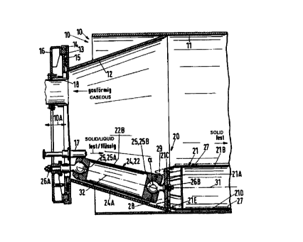
The revolving drum designated overall as 10 in Figure 1 is represented
rrxerely
schematically, in particular without insulation, heating, and revolving
apparatuses. It consists of a
cylindrical wall part 11 and .at each of its two ends, a cynical wall part I2,
as well as a flange 13
which is seated tightly sealed but free to rotate on a rotationally fixed
cover 16 by positioning and
sealing means 14 and 15 .in a conventional manner. The insulating, heating,
and revolving drive
means of the revolving drum axe conventional and left out in the drawing,
since they are not part
of the object of the invention. The cover 16 is provided with a material feed
17 and a gas suction
connector 18.
A rolling element, designated overall as 20, for cleaning of the inner wall of
the dxum, at
least in the area of the head on the entry side represented, consists of a one-
part rolling element
member 21 which via an intermediate member 24 is connected to the cover 16
free to swivel in all
directions and revolve via two revolving articulations constructed as ball and
sockets 25A and
25B. Fox this purpose the ball and socket 25A is firmly connected to the cover
16 via a screw
26A and the ball and socket 25B is ~unmly connected tv a front wall 21 A of
the rolling element
member 21 by means of a screw 26B.
The intermediate member 24 is configured as a conical hollow body which tapers
in cross
section in the direction of the cover 1 b and whose outer peripheral face
(generated surface) is held
a small, approximately uniform distance apart from the conical wall part 12 of
the revolving drum
10. Baked-on deposits which are thicker than the thickness of the spacing gap
24A therefore
cannot form, as a rule, so that the intermediate member 24 also generally
assumes the functiozz of
CA 02283302 1999-09-03
SEP-03-99 11:53 +49 201 9423020 P.28 R-196 Job-834
03!09/1999 17:48 +49-201-8423020 P, S $ K PATENTE S. 28
a second rvll.ing element member 22. Naturally, this intermediate or second
rolling element
member 24, 22 can also be provided with cleaning elements near the suzface,
such as are realized
on the first rolling element member 21 in the form of the spiral cleaning
strip 27.
The first rolling element member 21 has a cylindrical surface zone 21B as well
as a conical
surface zone 21C adjacent thereto in the direction toward the cover 16. These
surface zones, or
generated suxfaces, are associated, on the one hand, with the cylindrical wall
part 11 of the
revolving drum 10 and, on the other, with the conical wall part 12 of the
revolving drum 10 such
that the respective cylindrical and the respective conical surface zones .form
a gap 21D or a gap
21 E. These gaps define the zones of contact or zones of least mutual
separation. Due tv th,e
approximately equally-sized conical angles of the conical zone 21 C of the
first rolling element
member 21 and of the conical wall part 12 of the revolving drum 10, the gap
21E is approximately
uniformly wide. Even without having particular cleaning elements, the conical
zone 21 C has a
cleaning effect (as is the case for the intermediate member 24 or second
rolling element member
22). Cleaning elements can of course be provided in addition to enhance the
cleaning effect. The
rolling element member 21A therefore cleans two cones of the surface of the
revolving drum 10 at
an angle to one another in a single operational process and also covers the
transitional area of
these two zones of the surface.
In order to achieve a thorough cleaning effect for coupled rolling element
members whose
rolling axes 3 l, 32, as in the ernbodiraent of 1~igure 1. forma an angle
alpha, the front face of the
one rolling element rne~oaber 21 has a central recess 28 into which the front
end of the adjacent
rvHing element member 22 can dip at least partially. The same effect is
achieved if the outer wall
forming the conical zone 21 C of the first rolling element member 21 extends
out over the front
wall 21 A, in particular flushly, and thereby the spacing gap to the second
rolliutg element merxxbcr
22 is largely covered on the outer side of the break. In Figure 1 a front ring
29 is thus represented,
merely by way of example.
In the embodizxxent according to Figure 2, a first rolling element member 21
is formed in
lobular shape az~d has a fast cynical surface zone 21 C' axxd a second conical
surface zone 21 C"
Both have a common rolling axis 31 and form the generated surfaces of two
frustums which are
connected to one another on an equally large base with opposing, if necessary,
different conicities.
The individual rolling element attachment tv a positivnally fixed end wall of
the revolving drum
10, not represented in greater detail, can be configured similarly to the ball
and socket 25A. The
cleaning of the revolving faces 11 and 12 is done in a similar manner to that
described in
connection with Figure 1.
A second rolling element member 22 can adjoin this first rolling element
member 21 in a
similar onanner, as represented in Figure 1. Tklis is reproduced in Figure 2
with dotted lines. As a
firrther alternative in the case of multiple rolling elements, each of the
rolling element members
CA 02283302 1999-09-03
6
can also be provided with only one cleaning zone and individual rolling
element members can
form an angle deviating from 180° and be assigned to zones of the
revolving drurn, each inclined
differently.
Finally, Figure 3 shows a conical first rolling element member 21 which is in
turn fastened
by an intermediate member 24 Formed as a chain to a positionally fixed end
area of the revolving
drum I O and is connected in the center to the front wail 2 I A on the entry
side via a revolving
articulation ZS in the manner of a Cardan joint. The edge 2IF on the front
side for-nned between
the front inner wall 2IA and the generated surface 21B of the cone is disposed
in the area of the
break between the conical and cylindrical wall part of the revolving drum 10
such that even the
zone of conical tapering is cleaned, at least in the transitional area. Such a
cleaning effect also
occurs if the cross-sectional taperyxrg of the revolving drum 10 is not
configured cynically but
rather in steps as represented in Figure 3 by dotted tines.
CA 02283302 1999-09-03