Note: Descriptions are shown in the official language in which they were submitted.
CA 02283441 1999-09-23
TITLE OF THE INVENTION
BALL GAME PRACTICE APPARATUS
BACKGROUND OF THE INVENTION
The present invention relates to a ball game practice apparatus such as tennis
practice apparatus, and more specifically, to a practice apparatus equipped
with a practice
apparatus main body which can control the ball flying range.
Because this kind of practice apparatus for ball games, such as tennis
practice
apparatus, are able to be used for exercise in a comparatively small place,
they are offered
for the use of exercises of a wide range of exercisers from beginners to
experts of a certain
level. Practice apparatus with a wide variety of functions have been developed
to realize
the flying of balls close to that in actual play so that exercises similar to
actual games can
be experienced and at the same time, various changes can be realized even in
returning
balls. The present inventor has invented practice apparatus that can achieve
ball returns
close to those in actual play by selecting suitable elastic means for hanging
balls from the
rubber material and shapes and making contrivances in the construction of
elastic means
without adopting conventional methods that depend only on the elasticity of
rubber (USP
4,902,012, USP 5,098,094). The invention does. not provide ball returns of a
specified
trajectory after the ball is hit but is contrived to achieve returns full of
varieties close to
those in actual games.
However, in the case of conventional techniques, to realize the flying close
to the
flying condition of balls in actual play, the elastic means connected to the
ball must have a
length exceeding a certain length. Consequently, a large distance is required
from the
column to the ball hanging position, and the height that exceeds a certain
level must be
provided for the apparatus, requiring a large space, and the construction of
the whole
apparatus must be kept large.
In addition, because the contrivance to achieve returns full of varieties
depends
on the fixed type tilting angle provided at the rebounding board arranged
primarily ahead
CA 02283441 2005-06-08
of the ball flying direction, there is no denying that returns are monotonous
to a certain
extent.
In addition, in the case of the conventional technique, there are cases in
that
rubber hanging the ball is twisted because of the accumulation of ball
rotations generated
as a result of long and severe practices. Due to this twist, the ball hanging
length
becomes excessively short or because the ball hanging rubber comes in contact
with the
rubber fixed to a frame at one point, there is a problem in that the contact
point is
damaged.
Under these circumstances, it is the main object of the invention to provide a
ball
game practice apparatus which has solved problems of conventional techniques,
and to
realize a batted ball in the flying condition close to that of actual play
without making the
size of the whole apparatus large.
In addition, it is a further object of the invention to provide a ball game
practice
apparatus that can produce returned balls full of varieties and more like
those experienced
in actual games.
It is still a further object of the invention to provide a ball game practice
apparatus, the durability of whose elastic means is further improved.
SUMMARY OF THE INVENTION
The present invention provides a ball game practice apparatus comprising
(A) a ball, and (B) a practice apparatus main body having the ball hanging
therefrom, the practice apparatus main body having (i) a frame having a front
end
and a rear end, (ii) an elastic means connected to the frame, and (iii) a
column for
supporting the frame at a support location approximately midway between the
front
end and the rear end of the frame wherein the column is adjustable to secure
the
frame at the support location in a desired vertical position, wherein the
frame is
adapted to position the ball at a specified predetermined position via the
elastic
means, the elastic means includes a frame connection extending along the frame
and
mounted to the frame, a ball connection from which the ball hangs, and at
least a
pair of turn-back portions each having a smoothly rotatable turn-back
mechanism,
2
CA 02283441 2005-06-08
wherein the frame connection of the elastic means is supported by the frame
and is
turned back by the pair of turn-back portions, wherein the pair of turn-back
portions
is mounted to the frame such that the turn-back portions are separated from
each
other and the column for supporting the frame is interposed therebetween,
wherein
the frame connection of the elastic means extends in a longitudinal direction
of the
frame and is positioned substantially in parallel with the frame, and has a
portion
which is turned back by the pair of turn-back portions into a direction
substantially
parallell to the frame, wherein the ball hung from the ball connection is
positioned at
the outside of the pair of turn-back portions and at a distal end side of the
frame,
wherein the rear end of the frame is restrained by a telescopic element which
may
be adjusted to a predetermined length to vertically position the rear end of
the
frame, and wherein the frame is permitted to rotate about the column during
play:
The present invention also provides a ball game practice apparatus
comprising a vertically adjustable column, a frame having a front end and a
rear
end an<i pivotally supported on the column approximately midway between the
front
end and the rear end of the frame, wherein the column may be vertically
adjusted to
vertically adjust the position of the frame at the column, a telescopic
element
restraining the rear end of the frame, wherein the telescopic element may be
adjusted to a predetermined length to vertically position the rear end of the
frame,
and an elastic means attached to the frame the elastic means including at
least a pair
of smoothly rotatable pulleys attached to the frame, a frame connecting line
extending along the frame, attached to the frame along a substantially
parallel path,
having a portion which is turned back by the pair of pulleys so as to become
substantially parallel with the frame, and reeled about the pulleys, a ball
connection
attached to the frame connecting line, and a ball supported on the ball
connection,
wherein the ball supported on the ball connection is positioned at the outside
of the
pair of pulleys and at a distal end side of the frame.
The present invention also provides a ball game practice apparatus according
to the invention comprises a ball, a practice apparatus main body that hangs
the ball
and at l;he same time regulates the ball flying range, the practice apparatus
main
body possessing a frame that can hang the ball at a specified position via an
elastic
means .and a column for supporting this frame, and the elastic means
comprising a
2a
CA 02283441 2005-06-08
frame connection extended along the frame and mounted to the frame and a ball
connection that hangs the ball, characterized by the frame connection of the
elastic
means mounted to the frame which is turned back by at least a pair of turn-
back
portions with a rotatable turn-back mechanism.
If the practice apparatus is configured in this way, when the elastic means
extends
as the ball is hit, the frame connection that is turned back from the turn-
back portions and
has sufficient length can eliminate resistance at the turn-back portion as
much as possible
2b
CA 02283441 1999-09-23
and smoothly extends, and flying of hit ball close to that in actual play can
he realized.
Even an exerciser who is good at hitting hard and has strong hitting force,
satisfactory
extension of the elastic means can be achieved, and flying of the ball similar
to that at
actual play is enabled. In addition, because the rebounding ball is returned
with the
elastic force of the elastic means that extends sufficiently, it has an effect
that the return
speed is not unnatural.
It is preferable that the turn-back mechanism of the turn-back portion is
isolated
and turns back the frame connection in such a manner to avoid contacts with
frame
connections.
If this is configured in this way, it is possible to prevent generation of
contact
resistance caused by overlapping of frame connections, and flying of the ball
can be
brought as close as to that in the actual play. In addition, if the number of
turn-back
connections are increased to secure the extension rate of the frame
connections, contact of
the relevant elastic means that comprise these frame connections can be
avoided. As a
result, unnatural ball flying due to contact resistance between elastic means
does not occur,
and it is convenient for the people to carry out exercises still closer to
actual play.
The frame may be configured to be rotatably pivoted to the column.
If the practice apparatus is configured in this way, hitting the ball hung on
the
frame rotates the frame around the axis of the column that supports the frame,
and it is
therefore preferable that return balls like those in actual play full of
variations can be
obtained without arranging the rebounding board ahead and utilizing the
rebound.
A rotation restrictor for restricting the rotation range of the frame that
rotates
around the column may be provided.
Because configuring in this way can restrict the motion of the frame on which
the
ball is hung to a specified range, it is possible to carry out more controlled
hit ball
treatment of the returned ball, and exercise in which rallies continue long
time can be
experienced, which is desirable.
It is preferable that the ball connection of the elastic means comprises a
plurality
of portions forming loops, and each one of these portions are connected via a
twist
straitening mechanism, and at the same time, the contact position of the ball
connection
can be varied at each contact position.
CA 02283441 1999-09-23
Configuring in this way can positively cancel detrimental effects caused by
twist
arising from rotation of the elastic means itself even when the strongly hit
ball is violently
rotated, and can improve the durability without generating damage to the
elastic means,
and at the same time enables the continuation of stable ball hitting
exercises. And even if
the exercise is continued for a long time, it is possible to avoid contact of
the ball with the
same place by changing the contact position of the elastic means comprising
the ball
connection, effectively reduce troubles arising from wear and damage of the
contact place,
and remarkably improve the durability of the whole apparatus.
A rebounding board of the ball may be installed ahead of the ball flying
direction.
In the case of the invention, the rebounding board is not always required, but
installing a rebounding board ahead of the ball flying direction can achieve
still more
variable return balls, which is preferable.
When the ball rebounding board has its rebounding board surface angle
changeable, still more variable return balls can be obtained and it is
preferable.
It is also possible to install a target equipped with a return prevention
mechanism
that prevents return of the flown ball ahead of the ball flying direction.
Configuring in this way can positively identify that the ball hits the target
even
when it is difficult to identify whether the struck ball hits the target or
not when the ball hit
by the exerciser flies excessively fast.
The downward displacement restrictor for restricting the downward displacement
of the frame connection of the elastic means may be installed to the frame of
the invention.
Configuring in this way can restrict the downward displacement of the ball
even
when the ball is hit hard, and it is convenient that the return ball is easy
to return to the
original hung position.
The downward displacement restrictor installed near one end of the frame may
comprise combinations of a plurality of annulus rings of varying sizes.
Configuring in this way can effectively reduce contact resistance between the
elastic means and annular rings at individual annular rings because the ball
load is
distributed to a plurality of annular rings, and it is desirable that the ball
flying associated
with hitting of the ball becomes similar to the natural struck ball free of
restrictions.
It is preferable that at least one of the downward displacement restrictors is
4
CA 02283441 1999-09-23
equipped with an isolating mechanism for reducing contact with elastic means.
As the ball is hit, the elastic means connected to the ball is pulled with a
strong
force and comes in contact with the elastic means existing in parallel, but if
the contact of
these elastic means is great, there is a case in that resistance is generated
in movement of
the elastic means or eventually the elastic means is damaged. As a result, the
durability
of the elastic means is detrimentally affected and at the same time, flying of
the struck ball
is given unnatural restriction, which is not preferable. Consequently,
providing this kind
of isolating mechanism not only is able to increase the life of the elastic
means but also the
flying of the struck ball becomes natural like an actual struck ball.
BRIEF DESCRIPTION OF THE DRAWINGS
FIG. 1 is a perspective view showing the overall arrangement of ball game
practice apparatus according to the invention;
FIG. 2 is an enlarged perspective view of the lower part of the column of the
practice apparatus proper shown in FIG. 1;
FIG. 3 is a plan view explaining the operation of the practice apparatus
proper
shown in FIG. 1;
FIG. 4 is an enlarged perspective view of the ball connection of the elastic
means;
FIG. 5 is an enlarged sectional view of the isolating mechanism;
FIG. 6 is an enlarged side view of the turn-back section; and
FIG. 7 is an elevation of the target apparatus.
DETAILED DESCRIPTION OF THE PREFERRED EMBODIMENTS
Referring now to drawings, the embodiments of the ball game practice apparatus
according to the invention will be described in detail hereinafter using
tennis practice
apparatus for an example.
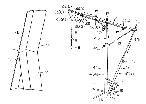
FIG. 1 shows an overall construction of a tennis practice apparatus equipped
with
a practice apparatus main body 1 that hangs a ball B, and a rebounding board 7
against
which the flown ball B rebounds. The practice apparatus main body 1 comprises
a frame
3 which can hang the ball B at a specified position via an elastic means 2 and
a column 4
that supports the frame 3. The column 4 further comprises a main column 4'
that
CA 02283441 1999-09-23
rotatably supports the frame 3 with the nearly center portion of the frame 3
as the rotating
center and a sub-column 4" that supports the other end portion opposite to the
position
(one end side) that hangs the ball B, of the end portions of the frame 3. The
main column
4' is preferably about 1600-2000 mm high. These main column 4' and sub-column
4"
form pipes and are of a telescopic construction. That is, the extending
portions 4'b, 4"b
that can extend upwards from each of the basis 4'a, 4"a at the lower part of
the main
column 4' and sub-column 4" are able to be housed inside the pipe that
composes the basis
of the column 4' and sub-column 4", respectively. These columns 4', 4" shown
in FIG. 1
can be extended in two stages, but they may be extended in multiple stages or
may be in a
fixed length that does not extend. When the extending portions 4'b, 4"b are
extended to a
specified length, they can be fixed in place by general screw type stoppers
4'c, 4"c.
To the lower end portion of the main column 4', legs 11 extended in four
directions so that the main column 4' can be stably erected are secured by
welding. The
length, thickness, etc. of the legs 11 may be any sizes that enables stable
erection of the
column. However, the lower end portion of the sub-column 4" is not secured to
the main
column 4' and the legs 11, but is loosely inserted and fitted in a through
hole 1 lb formed
in a triangle plate 11 a stretched across the intersection of two pieces of
legs 11 and
secured by welding in a depth that would not allow the sub-column to easily
jump out.
That is, the lower end portion of the sub-column 4" is supported at one point
in such a
manner to enable it to make precession around the main column 4'. Naturally,
the lower
end portion of the sub-column 4" is not limited to the system for inserting
the lower end
portion of the sub-column 4" into the hole 11 b formed in the triangle plate
11 a but may be
supported at one point by other configuration if the lower end portion does
not easily
move upwards and jump out as a result of the hitting play of the ball B.
Because the lower end portion of the sub column 4" is supported at one point
to
enable it to make precession around the main column 4', precession of the sub-
column 4"
is generated by the hitting of a ball by the exerciser and the frame 3 rotates
and moves
following the movement of the ball B as the ball B flies, as shown in FIG. 3.
In such
event, it is convenient to install a rotation restrictor 5 for restricting the
rotation range of
the frame 3 as shown in FIG. 2, because the movement of the frame 3 can be
controlled.
This rotation restrictor 5 comprises two pieces of chains with some allowance
in length
6
CA 02283441 1999-09-23
which connect two column supporting members 16 that reinforcedly support the
leg 11 of
the main column 4' to the sub-column 4". When the sub-column 4" makes
recession and
moves as the ball B is hit, either one of the two chains composing the
rotation restrictor 5
operates in the direction to restrict the movement of the sub-column 4". If a
chain
hitching section is provided on either the sub-column 4" side to which the
chain is
connected or on the column supporting member 16 side, the degree of allowance
can be
adjusted, and in addition, the restriction range can be changed with this.
That is, if
changes of the return ball after hitting are desired to be further increased,
the allowance of
the rotation restrictor 5 should be increased, and further, the rotation
restrictor S may be
removed. With this configuration, it becomes possible to provide changes to
the return
ball without depending on the profile of rebounding board, in particular,
rebounding angle,
as in the case of conventional techniques, and exercises close to actual play
can be carried
out. It is also possible to use strings, ropes, belts, wire, etc. in place of
the chains used for
the restrictor 5.
It is preferable to connect the main column 4' to the other end portion of the
frame
3 opposite to one end portion to which the ball B is hung, with another chain
12, because
the sub-column 4" is not subject to unintentional variations and achieves
stable movement
in a specified range even when the exerciser makes violent hitting plays.
The main column 4' and the frame 3 are connected free to be liberated and
fitted
by screwing a stopper 13 into the top threaded on the inside of the extending
portion 4'b of
the main column 4' which passes through the frame 3 and at the same time by
supporting
the frame 3 to a protrusion (not illustrated) provided on the outside of the
extending
portion 4'b of the main column 4'. Similarly, the sub-column 4" and the other
end
portion of the frame 3 are connected free to be liberated and fitted by
screwing a stopper
14 into the top threaded on the inside of the extending portion 4"b of the sub-
column 4"
which passes through the frame 3 and at the same time by supporting the frame
3 to a
protrusion (not illustrated) provided on the outside of the extending portion
4"b of the
sub-column 4". Naturally, if the chain 12 for connecting the main column 4' to
the other
end portion of frame 3 are provided, the stopper 14 does not always
necessarily have
functions to screw and fix, but may only have a function to prevent the other
end side of
the frame 3 from coming out from the sub-column 4". The distance from the
stopper 13
7
CA 02283441 1999-09-23
to the stopper 14 is preferably about 300-800 mm.
The frame 3 forms a pipe in the similar manner as in the case of the main
column
4' and sub-column 4" and is of a telescopic construction. From the basis 3a to
the tip end
side of the frame 3, a telescopic extending portion 3b is housed in the pipe
composing the
basis 3a, and when the extending portion 3b is extended to a specified
position, it is fixed
in place with the stopper screw 15 installed at the basis 3a. This frame 3 may
not be of a
telescopic system as illustrated but may be of a fixed length system.
Specifically, the
frame 3 is desirable to be about 2000-4000 mm.
On the bottom side of the frame 3, an elastic member 2 comprising rubber is
placed along the erecting direction of the frame 3. This elastic member 2
comprises a
frame connection 2a along the longitudinal direction of the frame 3 and a ball
connection
2b which is connected to the frame connection 2a downward from the vicinity of
one end
portion of the frame 3 and to which the ball B is hung. Of the elastic means,
the frame
connection 2a has the downward displacement of the frame connection 2a
restricted by the
downward displacement restrictor 6 equipped to the frame 3. That is, because
the
downward displacement of the ball can be restricted to a certain extent by the
downward
displacement restrictor 6 even when the ball is hit hard, the return ball is
easy to return to
the original hanging position, which is convenient for continuing hitting
exercises.
The downward displacement restrictor 6 comprises combinations of a plurality
of
annular rings 6a, 6b, 6c of varying sizes installed in the vicinity of one end
portion of the
frame 3 and an annular ring 6d installed to the bottom nearly at the center
portion in the
longitudinal direction of the frame 3. The annular ring 6a is installed near
the top end of
one end portion of the frame 3 and to the bottom of the frame 3 closer to the
column, an
annular ring 6b in slightly larger diameter than that of the annular ring 6a
is installed, and
between these annular rings 6a, 6b, the ball B is positioned to hang down. The
annular
ring 6c has a diameter nearly same as that of the annular ring 6a on one end
portion side
and is installed on the bottom of the frame 3 further closer to the column
than the annular
ring 6b. The annular ring 6b is not always necessary as a downward
displacement
restrictor 6, but slightly increasing the diameter of the annular ring 6b from
that of the
annular ring 6a can disperse the load of ball B to annular rings 6b and 6c,
and as a result,
the contact resistance between the elastic member and the annular ring in each
of the
CA 02283441 1999-09-23
annular rings can be effectively reduced, and the flying of the ball as a
result of hitting the
ball B becomes free of restriction and close to that of the naturally hit
ball, which is
preferable. Naturally, on the annular ring 6a side, a combination of annular
ring 6b and
6c may be provided, and furthermore, the number of installations of the
annular rings with
varying diameters may be increased.
The annular ring 6d installed on the bottom at nearly center portion in the
longitudinal direction of the frame 3 may have a configuration similar to that
of annular
rings 6a, 6b, 6c, but it is preferable to be configured to have an isolating
mechanism 8
equipped for isolating each of the elastic means individually as shown in FIG.
5. If
configured in this way, when the frame connection 2a of the elastic means is
composed
with a plurality of pieces as described later, the resistance caused by mutual
contacts
generated as a result of hitting of the ball B can be eliminated as much as
possible, which
is convenient. This isolating mechanism 8 comprises a plurality of short pipes
and each
pipe is designed to allow one piece of connection 2a to pass, and is installed
to the outer
circumference on the bottom side of the basis 3a of the frame 3 by a joining
means such as
adhesives or welding. The profile of each pipe that composes the isolating
mechanism 8
should be such that the elastic means can smoothly slide inside. In addition,
the pipe
inside of the isolating mechanism 8 may be provided with resin coating such as
Teflon
(trade mark), etc. that would achieve low friction in the pipe inside. The
annular rings 6b,
6c may have the configuration equipped with the isolating mechanism 8 in the
similar
manner
Next, the discussion will be made on the placing route of the frame connection
2a
of the elastic means. The frame connection 2a originates from the elastic
means winding
portion 17 mounted in the vicinity of the top end of the extending portion 4'b
of the main
column 4' and extendedly installed towards one end side of the extending
portion 3b along
the longitudinal direction of the frame 3. And the frame connection 2a passes
the inside
of the isolating mechanism 8, one of the members composing the annular ring
6d, has the
direction changed by the front end side turn-back portion 26 equipped with the
turn-back
mechanism later discussed, passes the inside of the isolating mechanism, one
of the
members composing the annular ring 6d again, has the direction changed by the
rear end
side turn-back portion 18 later discussed, and again passes the inside of the
other isolating
9
CA 02283441 1999-09-23
mechanism 8, one of the members composing the annular ring 6d. Then, the frame
connection 2a further passes the annular ring 6c, then, the inside of the
annular ring 6b,
and advances as if it crosses the ball connection 2b of the elastic means
later described.
If configured in this way, the frame connection 2a of the elastic means is
positively
extended to the length exceeding the length from the elastic means winding
portion 17 to
the intersection with the ball connection 2b of the elastic means as the ball
B is hit, and
extension of sufficient length is secured at this portion as the ball is hit,
and flying of ball
close to that in actual play can be realized, which is preferable.
In addition, the frame connection 2a of the elastic means enters from the
inside of
the annular ring 6a mounted to the vicinity of the top end of one end portion
of the frame 3
and swings outwards, and then, passes the inside of each of the annular rings
6b, 6c,
towards the original direction. The frame connection 2a has the direction
changed
oppositely after it reaches the rear-end side turn-back portion 18 equipped
with the turn-
back mechanism mounted to the bottom in the vicinity of the other end side of
the frame 3
as shown enlarged in FIG. 6, reaches the isolating mechanism composing the
annular ring
6d, where it also passes the inside of another isolating mechanism 8 and
reaches the front
end side turn-back portion 26 equipped with the turn-back mechanism. The front
end
side turn-back portion 26 may be configured in the similar manner to that of
the rear end
side turn-back portion 18 shown in FIG. 6, and is mounted to the lower portion
on this
side of the annular ring 6c in the vicinity of one end side of the extending
portion 3b of the
frame 3 as shown in FIG. 1 and FIG. 4. By the way, it is preferable to install
the front
end side turn-back portion 26 at the distance about 150-400 mm from the top
end of one
end side of the extending portion 3b of the frame 3. In addition, the frame
connection 2a
of the elastic means has the direction changed by the front end side turn-back
portion 26,
passes the inside of the other isolating mechanism 8 of the annular ring 6d,
and finally
returns and is fixed to the elastic means winding portion 17. Now, the rear
end side
turn-back portion 18 and the front side turn-back portion 26 compose one pair
of turn-
back portions.
Naturally, the frame connection 2a that passes the front end side turn-back
portion 26 may be allowed to further reach the rear end side turn-back portion
18 and
repeat turn-backs again, and in such event, the frame connection 2a is further
extended,
CA 02283441 1999-09-23
generating effects to further increase the extension of the elastic means as a
result of
hitting the ball, which is particularly suited for the exercise of the
exerciser who is good at
hard hitting.
The rear end turn-back portion 18 and the front end turn-back portion 26 are
configured to be equipped with a pulley 19, both of which the frame connection
2a passes
vertically without coming into contact to each other, and the pulley 19 is
pivoted to the
shaft 25 to enable smooth rotation. The pulley 19 composes a turn-back
mechanism.
The number of the pulley 19 may be increased and decreased as required in
accord with
the number of elastic means that passes the pulleys. Iii short, the number of
pulleys
which can avoid contacts between elastic means as much as possible and prevent
generation of contact resistance should be selected. And the surface of the
pulley 19 is
preferably smooth enough to minimize contact resistance with the frame
connection 2a of
the elastic means, and it is further preferable if the surface is coated with
Teflon (trade
mark). The pulley 19 itself may be composed with a ball bearing or a ball
bearing may
be built in for the contact between the pulley 19 and the shaft 25.
By sufficiently securing the length of the frame connection 2a of the elastic
means in this way, exercises close to actual play can be achieved without
generating
unnatural strong tension to extension of the elastic means by the hitting of
ball B. The
number of direction changes of the frame connection 2a of the elastic means is
naturally
not limited to this embodiment, but may be further increased or decreased.
On the other hand, the ball connection 2b of the elastic means comprises the
first
connection 2b 1 of the annular form in contact with the frame connection 2a,
the second
connection 2b2 located below and connected via a twist straightening mechanism
9, and
the third connection 2b3 connected via another twist straightening mechanism
9.
Naturally, the number of these connections is not limited to this, and,
similarly, the
number of twist straightening mechanisms 9 that are intervened in each
connection may
be changed as required in accord with the number of connections. The first
connection
2b1, second connection 2b2, and third connection 2b3 are set to nearly same
length, but
these lengths may be varied as required.
Specifically, the hanging length of the annular first connection 2b1 is about
200-
400 mtn, those of the second connection 2b2 and the third connection 2b3 are
preferably
CA 02283441 1999-09-23
about 300-600 mm.
The twist straightening mechanism 9 comprises two top and bottom annular rings
9a, 9c in contact with the elastic means and a jig 9b which is intervened
between these two
annular rings 9a, 9c and freely fitted to a protrusion (not illustrated)
extendedly provided
from one end of the annular rings 9a, 9c. Installing this twist straightening
mechanism 9
can alleviate the burden caused by the twist at the connections of individual
elastic means
even when the ball hit by the exerciser violently rotates, and it is extremely
preferable in
improving the durability of the elastic means. In addition, because the ball
connection
2b of the elastic means is divided and formed in a plurality of loops, it is
possible to move
and change the contact point between the annular rings 9a, 9c and the ball
connection 2b
comprising the twist straightening mechanism 9 as required, and the contact
condition at
the same position which continues for a long time can be avoided, and
therefore, the life of
the ball connection 2b of the elastic means can be remarkably improved, which
is
preferable. The similar thing can be said to the contact between the ball
connection 2b
and the frame connection 2a. That is, because the ball connection 2b of the
elastic body
is formed in a loop, point contact of both members can be avoided, and the
frame
connection 2a carries out the pay-off from the elastic means winding portion
17 as
required and at the same time, takes up or cuts the excess at the tail end
side, thereby
avoiding contact at the same position (one point contact).
On the other hand, the rebounding board 7 is not always necessary in
implementing the embodiment, but the presence of the rebounding board can
provide
return balls with still more variations and enables more realistic exercises.
For example, the rebounding board 7 used in this embodiment, as shown in
FIG.1,
comprises main rebounding boards 7a, 7b whose upper portion is slightly tilted
to this side
and folded right and left into two, and twofold sub-rebounding boards 7c, 7d
tilted
opposite to the main rebounding board and located at the portion lower than
the nearly
central portion of the height of the main rebounding boards 7a, 7b. All of the
main
rebounding boards 7a, 7b and sub-rebounding boards 7c, 7d have the central
portion
slightly retracted to the backward side, and conversely, the right and left
outer end
portions are bent to be brought slightly closer to the ball side. The bending
angle of these
rebounding boards may be changed as required in accord with the purpose of the
exercise.
12
CA 02283441 1999-09-23
In this event, the top end side of the sub-rebounding boards 7c, 7d differs
from the bottom
end side, which is formed to be horizontal, and formed tilted in such a manner
that the top
end side is slightly higher towards the confluence center point of twofold sub-
rebounding
boards 7c, 7d. If configured in this way, the twofold main rebounding boards
7a, 7b and
twofold sub-rebounding boards 7c, 7d, the upper portions of which are slightly
tilted to
this side have the central portion slightly retracted towards the rear side,
and conversely,
the right and left end portions are bent in such a manner that they come
slightly closer to
the ball side. The bending angle of these rebounding boards may be changed as
required
in accord with the objects of the exercise. In such event, the top end side of
the sub-
rebounding boards 7c, 7d differ from the bottom end side which are formed to
be
horizontal, and formed tilted in such a manner that the top end side is
slightly higher
towards the confluence center point of twofold sub-rebounding boards 7c, 7d.
If
configured in this way, when the upper portion of the twofold main rebounding
boards 7a,
7b is tilted slightly to this side, the portion in which the contact portion
between the
twofold sub-rebounding boards 7c, 7d forms line contact also increases. That
is, since
both rebounding boards are folded in two, bringing both rebounding boards in
contact
essentially tends to generate point contact, but it is desirable that
instability of contact
portion resulting from such point contact can be avoided.
Together with the folding angle of both rebounding boards, the tilting angle
can
be manually or automatically changed. Though it is not illustrated, the lower
end portion
of sub-rebounding boards 7c, 7d are energized in advance using elastic means
such as
spring or rubber towards the retracting side, and the lower end portion of sub-
rebounding
boards 7c, 7d are pulled to this side manually or automatically using wire,
etc. against the
energization. In order to provide variations to return balls during exercise,
it is possible
to automatically repeat pulling and retracting operations of the lower end
portion of the
sub-rebounding boards 7c, 7d using a motor with an eccentric cam.
In addition, it is desirable to fix the position of the bend center of the
main
rebounding boards 7a, 7b and sub-rebounding boards 7c, 7d and at the same time
to urge
both end portions only in advance to the retracting side using elastic means
such as spring
or rubber, and to pull only both end portions of the sub-rebounding boards 7c,
7d to this
side against the urging manually or automatically using wire, etc., because
the opening
13
CA 02283441 1999-09-23
angle of both rebounding boards can be adjusted and changed. In this event, it
is
possible to automatically repeat pulling and retracting operations of both
side ends only of
the lower end portion of the sub-rebounding boards 7c, 7d using a motor with
an eccentric
cam.
The size of the main rebounding board may be, for example, about 1500-2000
mm high by about 400-1000 mm in total width, and the size of the sub-
rebounding board
may be, for example, about 600-1000 mm high by about 400-1000 mm in total
width.
[Another Embodiment]
When the practice apparatus main body 1 shown in FIG. 1 is used in exercising
tennis, in addition to the case in which the rebounding board 7 is placed in
front, a target
apparatus with a target 20 hung may be placed in front to carry out the
exercise. In such
event, the target apparatus may be arranged in place of the rebounding board 7
or side by
side. It is desirable to arrange the target 20 side by side with the
rebounding board 7
because more realistic exercise can be done. The target 20 is hung on the
other end of
the hanging means 22 installed to the top end of the expandable column 21 in
the
horizontal direction free to change positions. The target 20 comprises metal
or resin lines
and has an annular ring form, and the diameter is free to expand or contract.
That is,
both ends of the target 20 are made free, and superimposing both ends each
other, an
annular ring of a specified diameter is formed, and it is tightened to be
fixed by the
tightening means 23 equipped to the other end of the hanging means 22.
Releasing the
tightening means 23 can easily change the diameter of the target 20. The
target 20 is
further equipped with a storing portion 24, which is a return prevention
mechanism, at the
lower portion. If the flying speed of the ball hit by the exerciser is
excessively high, there
is a case in that it is unable to determine whether the ball enters the target
20 or not.
However, if a storing portion 24 is provided in the target 20, when the ball
enters the target
20, the ball connection 2b of the elastic means connected to the ball B enters
the inlet of
the storing portion 24, then enters the storing portion 24, stopping the
motion of the return
ball, and accurately indicating that the ball enters the target 20.
The elastic means 2 is preferably natural rubber, artificial rubber, etc,, but
in
order to achieve a specified tension, various kinds of materials and profiles
can be selected,
14
CA 02283441 1999-09-23
and the elastic means 2 may be a single rubber piece, or a plurality of rubber
pieces
arranged in parallel or in a lump, or the elastic means 2 may be a combined
string with the
restricting string that can control extension of rubber covered around rubber
With respect to the profile of the rebounding board 7, in the above
embodiment,
the rebounding board 7 has a construction to be folded into two from the
center portion
that forms right and left, but the invention shall not be limited by this, but
the rebounding
board may be one piece of plank or may be a turntable plate equipped with a
multiplicity
of folding processes.
The ball game practice apparatus according to the invention may be applied to
exercises of racquetball, squash racquets, etc. in addition to as tennis
practice apparatus.
In addition, besides hanging a rubber-ball baseball ball or hardball baseball
ball, a
net may be placed in the forward position to which the ball flies so that
batting exercise
can be carried out.
Furthermore, a soccer ball hung on the elastic means is arranged on the
ground,
and the target shown in FIG. 7 is arranged in front to carry out exercise.