Note: Descriptions are shown in the official language in which they were submitted.
CA 02283501 1999-09-07
F0252/2563
1
TRANSMISSION POWER CONTROL METHOD, MOBILE STATION,
BASE STATION AND RECORDING MEDIUM
BACKGROUND OF THE INVENTION
1. Technical Field
The present invention relates to a mobile station and a base
station in a mobile communication system with transmission power
control, a transmission power control method for mobile stations,
and a recording medium containing a program for achieving this
transmission power control method.
2. Background Art
In mobile radio systems, a service area is formed by providing
a number of radio zones which are circular areas centered around
base stations . For the purposes of covering the service area fully,
the base stations are provided so that a plurality of radio zones
will overlap at the edges of the radio zones.
Since the radio zones are centered around base stations, the
intensity of a desired signal to be received by a mobile station
in a service area will be high in the vicinity of the base station
but low near the radio zone edges . Since the communication quality
will be reduced if an interfering signal is stronger than the
desired signal, efforts have been made in existing mobile radio
systems to retain the service quality by performing handover to
an another radio zone capable of achieving better communication
quality when a mobile station has moved to the edge of a radio zone.
On the other hand, in CDMA (code division multiple access)
systems, transmission power control is performed to always keep
CA 02283501 1999-09-07
F0252/2563
2
the transmission power of mobile stations as low as possible for
the purposes of retaining capacity and quality and reducing
interference with other stations. The transmission power control
in these mobile stations is achieved by closed-loop control wherein
the transmission power is increased and decreased in accordance
with instructions given by the content of a single-bit transmission
power control signal (hereinafter referred to as a TPC bit) sent
from the base station.
Additionally, in the case of so-called soft handover, the
mobile station simultaneously connects to a plurality of
connectable base stations, and begins control of the switching
between radio zones . At this time, the mobile station detects the
TPC bits sent from the plurality of base stations by the
above-mentioned closed-loop control, and decides and controls its
own transmission power based on the content of the detected TPC
bits. Here, an example of the transmission power control during
soft handover in a mobile station is shown in Fig. 13. In the
example shown in Fig. 13, the transmission power is increased only
when the content of the TPC bits from all of the connected base
stations gives instructions for a transmission power increase (the
value of the TPC bit is "1" ) , and otherwise, the transmission power
is decreased.
However, during soft handover, the mobile station is not
capable of receiving the signals from all of the connected base
stations with the same quality. That is, there is a possibility
of the reception quality of the signal from a certain base station
being degraded. Degradations in the signal reception quality from
a base station mean an increase in the error rate for transfer of
the TPC bit from that base station. As described above, since a
CA 02283501 1999-09-07
F0252/2563
3
substance of the transmission power control of a conventional
mobile station is decided by combining the contents of all TPC bits
detected by the mobile station, an increase in the error rate for
transfer of the TPC bit from one base station will directly lead
to an increase in the probability that inappropriate transmission
power control will be performed.
Moreover, in the above-described example wherein the
transmission power is increased only when the contents of the TPC
bits from all of the connected base stations are "1" (when the TPC
bits from all of the connected base stations give instructions for
transmission power increase) as shown in Fig. 13, the probability
that the transmission power will be made smaller than necessary
will rise when the error rate for transfer of a TPC bit from a single
base station increases. This is due to the fact that if an error
arises in a TPC bit from a base station B when the combination of
TPC bits sent from a base station A and base station B is "11"
(transmission power increase), the reception pattern will become
"10", and will result in a transmission power decrease, whereas
if an error arises in the a TPC bit from base station B when the
combination of TPC bits sent from base station A and base station
B is "00", "10" or "O1" (transmission power decrease) , the reception
pattern will become "O1", "11" or "00", and will not always result
in a transmission power increase. This effect can be expected to
become more pronounced when the number of connected base stations
is large.
In the end, as is clear from what is described above, the
transmission power control of a conventional mobile station has
a problem in that when the reception quality of the signals from
any one of the base stations is low, then appropriate power control
CA 02283501 1999-09-07
F0252/2563
4
cannot be performed during soft handover, and the communication
quality is reduced.
SUMMARY OF THE INVENTION
The present invention has been made in view of such the
background, and has the object of offering a mobile station and
a base station, a transmission power control method for a mobile
station, and a recording medium containing a program for achieving
this transmission power control method, which are capable of
appropriately controlling the transmission power of the mobile
station during soft handover, even if the reception qualities of
the signals from the connected base stations are not the same.
In order to resolve the above-mentioned problems, the
transmission power control method of the present invention, the
method is the transmission power control method for a mobile station
simultaneously connected to a plurality of basestations,comprises
a receiving step for receiving a transmission power control signal
from each of said plurality of base stations in said mobile station;
a reliability level acquiring step for acquiring a reliability
level for each of said plurality of base stations; an object signal
acquiring step for determining an object signal from said
reliability levels acquired in said reliability level acquiring
step and said plurality of transmission power control signals
received in said receiving step; a control content deciding step
for deciding a control content of the transmission power of said
mobile station based on said object signal determined in said object
signal acquiring step; and a control step for controlling the
transmission power of said mobile station in accordance with the
CA 02283501 2002-11-04
control content decided in said control content deciding
step.
CA 02283501 2002-11-04
6
Additionally, in order to resolve the above-
mentioned problems, the mobile station according to the
present invention, the mobile station is capable of
simultaneously connecting with a plurality of base
stations, comprises receiving means for receiving a
transmission power control signal from each of said
plurality of base stations; reliability level acquiring
means for acquiring a reliability level with respect to
each of said plurality of base stations; object signal
acquiring means for determining an object signal based
on said plurality of transmission power control signals
received from said receiving means and said plurality of
CA 02283501 2002-11-04
7
reliability levels acquired from said reliability
acquiring means; control content deciding means for
deciding a control content of the transmission power of
said mobile station based on said object signal
determined by said object signal acquiring means; and
CA 02283501 2002-11-04
control means for controlling the transmission power in
accordance with said control content decided by said
control content deciding means.
CA 02283501 2002-11-04
a 9
BRIEF DESCRIPTION OF THE FIGURES
Fig. 1 is a block diagram showing the structure of
the essential portions of a mobile station according to
the first embodiment of the present invention.
Fig. 2 is a diagram showing the state of connection
between the mobile station and base stations during soft
handover in a CDMA system.
CA 02283501 2002-11-04
Fig. 3 is a diagram for explaining the combination
process by the combining portion of the mobile station
during soft handover in a CDMA System.
Fig. 4 is a diagram for explaining the
combination process by the combining portion of
the mobile station during soft handover
CA 02283501 1999-09-07
F0252/2563
11
in a CDMA system.
Fig. 5 is a diagram for explaining the combination process
by the combining portion of a mobile station according to
modification example 1 of a first embodiment during soft handover
in a CDMA system.
Fig. 6 is a diagram for explaining the combination process
by the combining portion of a mobile station according to
modification example 2 of a first embodiment during soft handover
in a CDMA system.
Fig. 7 is a diagram showing the transmission power control
amount by the mobile station in modification example 2.
Fig. 8 is a block diagram showing the structure of the
essential portions of a mobile station according to the second
embodiment of the present invention.
Fig. 9 is a diagram showing. an example of a combining process
based on a CRC verification result in a mobile station according
to a modification example of an embodiment of the present invention.
Fig. 10 is a diagram showing a summary of transmission power
control of a mobile station based on the reception level of an
up-going signal in a modification example of an embodiment of the
present invention.
Fig. 11 is a block diagram for explaining an example of the
structure of a mobile station according to the present invention.
Fig. 12 is a block diagram for explaining an example of the
structure of a base station according to the present invention.
Fig. 13 is a diagram for explaining the transmission power
control of a mobile station during soft handover in a conventional
CDMA system.
CA 02283501 1999-09-07
F0252/2563
12
PREFERRED EMBODIMENTS OF THE PRESENT INVENTION
Herebelow, a preferred embodiment of the present invention
shall be explained with reference to the drawings. The mobile
station in this embodiment basically has a structure which is based
on the structure of the mobile station of the present invention
which is described in the "Summary of the Invention" section.
Therefore, in order to simplify the understanding of the embodiment
here, a structural example of the mobile station of the present
invention is shown in Fig. 11.
In the structural example of Fig. 11, the mobile station
basically comprises receiving means, reliability level acquiring
means, object signal acquiring means, control content deciding
means, and control means. The control means controls signal
generating and transmitting means for generating and transmitting
signals to be transmitted. Additionally, thesignal (information)
supplied from the reliability level acquiring means to the object
signal acquiring means could be either singular or plural. For
example, when the reliability level acquiring means includes
weighting means, the plurality of weighted signals will be supplied
to the object signal acquiring means, but if it is possible to allow
the weighting coefficient to be 0, then there may be cases where
only a single signal is supplied to the object signal acquiring
means. The signal exchange relationship between the receiving
means, the reliability level acquiring means and the object signal
acquiring means is not restricted to that given as an example in
Fig. 11. For example, it is possible to have the reliability level
acquiring means (weighting means) output only weighting
coefficients (equivalent to reliability), and to directly input
CA 02283501 1999-09-07
F0252/2563
13
a plurality of signals outputted from the receiving means while
also inputting the weighting coefficients from the reliability
level acquiring means into the object signal acquiring means.
On the other hand, the base stations for communicating with
the above-described mobile station have basically the same
structure as normal base stations. However, when applied to a
mobile radio system which acquires the parameters indicating the
reliability level on the base station side, they will be provided
with parameter acquiring means as shown in Fig. 12.
A: First Embodiment
A-1: Structure
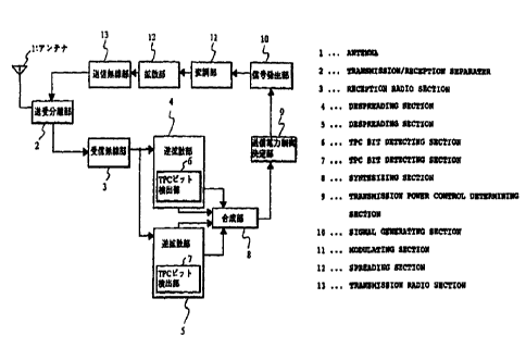
Fig. 1 is a block diagram showing the structure of the
essential portions of a mobile station 16 according to the first
embodiment, and the mobile station 16 having the structure shown
in this drawing is available to a CDMA system.
In Fig. 1, reference number 1 denotes an antenna for issuing
radio waves in accordance with a transmission signal to be
transmitted and for receiving radio waves from base stations and
generating corresponding reception signals, reference number 2
denotes a transmission-reception separating portion, reference
number 3 denotes a reception radio portion. The transmission-
reception separating portion 2 supplies transmission signals to
the antenna 1, and reception signals from the antenna 1 to the
reception radio portion 3.
Reference numbers 4 and 5 denote despreading portions for
despreading reception signals received from the reception radio
portion 3. As shown in Fig. 2, the despreading, which is performed
during soft handover where the mobile station 16 is connected
CA 02283501 1999-09-07
F0252/2563
14
simultaneously to the base station A14 and the base station B15,
is performed using a spreading code corresponding to base station
A14 in the despreading portion 4 and a spreading code corresponding
to the base station B15 in the despreading portion 5. In the
despreading portion 4, reference number 6 denotes a TPC bit
detecting portion for detecting and outputting TPC bits from the
signals obtained by despreading, and a TPC bit detecting portion
7 having the same function is provided within the despreading
portion 5. Furthermore, each TPC bit detecting portion determines
and outputs reliability information (e.g. a frame error rate) for
performing weighting which is proportional to the signal power and
inverse-proportional to the noise power, based on a reception power
(signal power) obtained by averaging the detected TPC bits by a
predetermined time constant and an average SIR (signal-to-noise
power ratio) for the most recent predetermined time period.
Reference number 8 denotes a combining portion for maximum
ratio combining two TPC bits outputted from the TPC bit detecting
portions 6, 7, which weights each TPC bit with corresponding
reliability information, then combines them on the IQ plane. The
coordinate system of the IQ plane is an orthogonal coordinate system
of in-phase components and orthogonal components. Reference
number 9 is a transmission power control deciding portion for
comparing signals combined by the combining portion 8 (object
signals, hereinafter referred to as combination signals) with a
preset threshold value, deciding the content of the transmission
power control based on the comparison result ( either a 1 dB increase
or a 1 dB decrease in the present embodiment ) , and controlling the
transmission power in accordance with this content. Reference
number 10 denotes a signal generating portion for generating a
CA 02283501 1999-09-07
F0252/2563
transmission signal having a transmission power controlled by the
transmission power control deciding portion 9. Reference number
11 denotes a modulating portion for modulating the transmission
signal generated by the signal generating portion 10, reference
number 12 denotes a spreading portion for spreading the
transmission signal modulated by the modulating portion 11, and
reference number 13 denotes a radio transmitting portion for
supplying the transmission signal spread by the spreading portion
12 to the antenna 1 via the transmission-reception separating
portion 2.
A-2: Operations
Next, the above-mentioned mobile station 16 shall be
explained in detail.
As shown in Fig. 2, during soft handover wherein the mobile
station connects simultaneously with the base station A14 and the
base station B15, the reception signals pass through the antenna
1, the transmission-reception separating portion 2 and the
reception radio portion 3, and are despread at the despreading
portions 4, 5. As a result, a signal corresponding to the base
station A14 is obtained in the despreading portion 4 and a signal
corresponding to the base station B15 is obtained in the despreading
portion 5. Then, a TPC bit from the base station A14 is detected
at the TPC bit detecting portion 6, and a TPC bit from the base
station B15 is detected at the TPC bit detecting portion 7.
Additionally, reliability information corresponding to the base
station A14 and reliability information corresponding to the base
station B15 are determined in the respective TPC bit detecting
portions 6, 7, and TPC bit combination is performed in the combining
CA 02283501 1999-09-07
F0252/2563
16
portion 8 based on the above-described TPC bits and reliability
information.
Fig. 3 is a diagram for explaining a combining process in the
combining portion 8, showing an example wherein the transmission
power is reduced by 1 dB. In this diagram, reference number 20
denotes a threshold value, represented by the line:
Q = -I
Additionally, reference number 17 denotes a vector representing
the TPC bit of the base station A, and reference number 18 denotes
a vector representing the TPC bit of the base station B. Each vector
has as a starting point the origin of the IQ plane, and has a length
which is in accordance with the corresponding reliability
information. The point opposite the origin in the parallelogram
having the two vectors as two adjacent sides is the post-combination
signal point 19, and the vector having the origin as a starting
point and the post-combination signal point 19 as the end point
represents the above-mentioned combination signal.
Since the post-combination signal point 19 is positioned on
the first quadrant side ( 1 dB decrease region) with respect to the
threshold value 20 in the example shown in the drawing, the content
of the transmission power control decided by the transmission power
control deciding portion 9 will be a "1 dB decrease" . Therefore,
the transmission power of the transmission signal generated by the
signal generation portion 10 will decrease by 1 dB. Of course,
the third quadrant side of the threshold value 20 is a 1 dB increase
region, and the threshold value 20 itself is a 1 dB decrease region.
On the other hand, Fig. 4 shows an example wherein the
transmission power is increased by 1 dB. In this drawing,
reference numbers 21, 22, 23 and 24 respectively denote a TPC bit
CA 02283501 1999-09-07
F0252/2563
17
of the base station A, a TPC bit of the base station B, a
post-combination signal point and a threshold value. Since the
post-combination signal point 23 is positioned to the third
quadrant side ( 1 dB increase region) with respect to the threshold
value 24 in the example shown in this drawing, the content of the
transmission power control decided by the transmission power
control deciding portion 9 will be a "1 dB increase" . Therefore,
the transmission power of the transmission signal generated by the
signal generating portion 10 will increase by 1 dB.
A-3: Summary
As explained above, according to the present embodiment, the
TPC bits received from a plurality of connected base stations are
combined, then compared with a threshold value, so as to avoid the
problem that the transmission power will always be decreased if
an error occurs in the transfer of one of the TPC bits when all
of the base stations are sending a TPC bit indicating an increase
of the transmission power. Additionally, the TPC bits are combined
after weighting them according to reliability information, so as
to reduce the influence of TPC bits from base stations which often
have transfer errors on the transmission power control of the mobile
station. As a result, it is possible to realize more accurate
transmission power control. Moreover, mobile stations are
normally provided with means for maximum ratio combining as a
measure for dealing with multi-path problems, and the precision
of transmission power control can be increased without adding any
new circuitry by making use of such means.
A-4: Modification Example 1
CA 02283501 1999-09-07
F0252/2563
18
Next, a modification example 1 of the above-described first
embodiment shall be explained. The structure of the mobile station
according to this modification example 1 is the same as that of
the mobile station 16 shown in Fig. 1, and the operations differ
only in the control content deciding process in the transmission
power control deciding portion 9. Therefore, only the control
content deciding process will be explained. In the transmission
power control deciding portion 9 in the present modification
example, the post-combination signal point from the combining
portion 8 is compared with two preset threshold values, and the
control content is chosen between a 1 dH decrease, maintenance and
a 1 dB increase.
Fig. 5 shows an example for a case where the transmission power
is decreased by 1 dB. In this drawing, reference numbers 25, 26
and 27 respectively denote a TPC bit of the base station A, a TPC
bit of the base station B and a post-combination signal point, and
reference numbers 28 and 29 denote different threshold values.
However, threshold value 28 is more toward the first quadrant side
than the threshold value 29. Since the post-combination signal
point 27 is positioned to the first quadrant side (1 dB decrease
region) with respect to the threshold value 28 in the example shown
in this drawing, the content of the transmission power control
decided by the transmission power control deciding portion 9
becomes a "1 dB decrease". Therefore, the transmission power of
the transmission signal generated by the signal generating portion
is decreased by 1 dB. Similarly, if the post-combination signal
point 27 is between the threshold value 28 and the threshold value
29, then "maintenance" control is performed, and if it is on the
third quadrant side (1 dB increase region) with respect to the
CA 02283501 1999-09-07
F0252/2563
19
threshold value 29, then a "1 dB increase" control is performed.
A-5: Modification Example 2
A modification example 2 which further modifies the
above-described modification example 1 shall be explained. As
with modification example 1, the structure of the mobile station
according to the modification example 2 is the same as that of the
mobile station 16 shown in Fig. 1. Additionally, the operations
of the modification example 2 differ from the operations of the
modification example 1 only with regard to the control content
deciding process in the transmission power controldeciding portion
9. As shown in Figs. 6 and 7, the transmission power control
deciding portion 9 according to the present modification example
takes the area between the two threshold values as the control range
between +1 dH and -1 dB. When the post-combination signal point
is within the control range, the value indicated by the combination
signal is placed in correspondence with the power control amount,
and when it is not within the range, a 1 dB increase or a 1 dB decrease
is performed as shown in Fig. 7. In Figs. 6 and 7, reference numbers
30, 31 and 32 respectively denote a TPC bit of the base station
A, a TPC bit of the base station B and a post-combination signal
point, and reference numbers 33 and 34 denote different threshold
values. However, the threshold value 33 is on the first quadrant
side with respect to the threshold value 34. Since the post-
combination signal point 32 is positioned on the threshold value
33 in the example shown in Fig. 6, the content of the transmission
power control decided by the transmission power control deciding
portion 9 becomes a "1 dB decrease" . Therefore, the transmission
power of the transmission signal generated by the signal generating
CA 02283501 1999-09-07
F0252/2563
portion 10 is decreased by 1 dB. Of course, if the post-combination
signal point 27 is between the threshold value 28 and the threshold
value 29, control is performed in accordance with a power control
amount (+1 dB to -1 dB) depending on the value indicated by the
combination signal.
A-6: Supplement to the First Embodiment
With regard to the TPC bit combining method in the above-
described first embodiment and modification examples, any publicly
known method may be employed. For example, it is possible to employ
a maximum ratio combining method wherein the reception signal for
each branch is weighted by a factor which is proportional to the
amplitude level and inverse proportional to the noise power prior
to adding, or to employ an equal-gain combining method wherein the
reception signals of all branches are weighted by the same factor
prior to adding (for details on these combining methods, see
"Advanced Digital Communications", Kamilo Feher et al.,
Prentice-Hall Inc., 1986 and "Modern Communication Principles",
Seymour Stein and J. Jay Jones, McGraw Hill Book Company). In
essence, any combining method can be employed as long as it has
sufficiently high precision in comparison to methods of combining
after detection of the TPC bits.
H: Second Embodiment
B-1: Structure
Fig. 8 is a block diagram showing the structure of essential
portions of a mobile station according to a second embodiment of
the present invention. In the drawing, those parts which are the
same as the parts in Fig. 1 are given the same reference numbers,
CA 02283501 1999-09-07
F0252/2563
21
and their explanation shall be omitted. The structure shown in
Fig. 8 differs from the structure shown in Fig. 1 in that instead
of a combining portion 8, a comparator 35 for receiving as inputs
reliability information outputted from the TPC bit detecting
portions 6, 7 and comparing them, and a selective combining portion
36 for receiving as inputs the TPC bits outputted from the TPC bit
detecting portions 6, 7 and selecting one for outputting to the
transmission power control deciding portion 9 are provided.
The comparator 35 generates a selection signal indicating the
TPC bit detecting portion 6 ( i. e. the base station A14 ) if the value
indicated by the reliability information outputted from the TPC
bit detecting portion 6 is greater than or equal to the value
indicated by the reliability information outputted from the TPC
detecting portion 7, and generates a selection signal indicating
the TPC bit detecting portion 7 ( i. e. the base station B15 ) in the
opposite case. The selective combining portion 36 has a switch
37 having two input ends for inputting the TPC bits outputted from
the TPC bit detecting portion 6, 7 and an output end connected
exclusively to one of the input ends. This switch 37 switches the
input end connected to the output end in accordance with the
selection signal generated by the comparator 35, and the selective
combining portion 36 outputs the TPC bit (object signal) outputted
from the output end of the switch 37 to the transmission power
control deciding portion 9.
B-2: Operations
Next, the operations of the above-described mobile station
shall be explained in detail. However, the explanations of the
parts which are the same as those in the first embodiment shall
CA 02283501 1999-09-07
F0252/2563
22
be omitted.
During soft handover, the TPC bit from the base station A14
and reliability information thereof are determined in the TPC bit
detecting portion 6, and the TPC bit from the base station B15 and
reliability information thereof are determined in the TPC bit
detecting portion 7. In the comparator 35, one of the above-
mentioned reliability information is compared with another one,
and a selection signal indicating the output source (TPC bit
detecting portion 6 or TPC bit detecting portion 7 ) of the one having
the higher value is generated. In the selective combining portion
36, the input end of the switch 37 which corresponds to the output
source indicated by the above-mentioned selection signal is
connected with the output end, and the TPC bit outputted from this
output end is outputted to the transmission power control deciding
portion 9.
B-3: Summary
As described above, according to the present embodiment, the
TPC bit having the highest reliability level is taken from among
the TPC bits received from a plurality of connected base stations,
so as to avoid the problem that the transmission power will always
be decreased if an error occurs in the transfer of one of the TPC
bits when all of the base stations are sending a TPC bit indicating
an increase of the transmission power. Additionally, it is
possible to reduce the influence that the TPC bits from base
stations with high transfer error rate have on the transmission
power control of the mobile station. As a result, a more accurate
transmission power control can be achieved.
CA 02283501 1999-09-07
F0252/2563
23
B-4: Supplement to the Second Embodiment
Modifications similar to those of modification examples 1 and
2 in the first embodiment can be made in the present embodiment
as well. That is, as in modification example 1, it is possible
to compare the output signal from the selective combining portion
36 with two preset threshold values, select the content of the
transmission power control of the mobile station from among the
three stages of increase, maintenance and decrease based on this
comparison result, and control the transmission power of the mobile
station with the selected control content, and as in modification
example 2, it is possible to change the transmission power of the
mobile station by a control amount depending on the output signal
from the selective combining portion 36.
C: Overall Supplement
While the average SIR in the most recent predetermined period
of time in the mobile station is used when determining the
reliability information in the above-described embodiments, it is
possible to use the instantaneous SIR in the mobile station, or
to use other parameters such as described below.
For example, CRC's contained in the downward signals from the
base station can be collated in the mobile station, and reliability
information can be generated in accordance with the verification
result (positive/negative). Here, an example of a combining
process using reliability information based on the verification
results of a CRC contained in the downward signal is shown in Fig.
9. In the example shown in this drawing, the verification result
for the CRC contained in the downward signal from the base station
A is "positive", while the verification result for the CRC contained
CA 02283501 1999-09-07
F0252/2563
24
in the downward signal from base station B is "negative", and as
is clear from the drawing, the influence on the post-combination
signal point 38 is large for the TPC bits 39 from the base station
A, and small for the TPC bits 40 from the base station B. That
is, an effect similar to that of the first embodiment is obtained.
Of course, the above-mentioned reliability information can be used
in the case of selecting one of the TPC bits. Since the CRC's are
appended in frame units, the mobile station must wait until the
reception of the downward signal of one frame is completed before
collating the CRC of the frame containing the TPC bit which is to
be processed, thus causing a control delay, but if the reliability
information of the TPC bit in the current frame is generated based
on the CRC verification result of the previous frame, then the
above-mentioned control delay can be avoided.
Additionally, the reliability information can be generated
based only on the reception level of the downward signal in the
mobile station, or the reliability information can be generated
based on only one parameter from among the above-mentioned average
SIR, instantaneous SIR and CRC verification result. Of course,
the reliability information may also be generated by combining the
various parameters as is appropriate.
Additionally, in the above-described embodiments, the
various parametersfor determining the reliability information are
determined from the downward signal, but they may also be determined
from the upward signal. Here, an example wherein transmission
power control of the mobile station is performed based on the
reception level of the upward signal is shown in Fig. 10. In the
example shown in this drawing, the upward signal from the mobile
station 41 is received by the base station C42 and the base station
CA 02283501 1999-09-07
F0252/2563
D43, the reception levels of the upward signals received in the
base stations are measured, and the measurement results (30 in the
base station C42 and 5 in the base station D43 ) are inserted into
the downward signals to the mobile station 41. The mobile station
41 receives the downward signals, and takes the reliability level
of the base station C as being, for example, 30 based on the
measurement result in the downward signal from the base station
C42, and takes the reliability level of the base station D as being,
for example, 5 based on the measurement result in the downward
signal from the base station D43. The subsequent process is
similar to the process used in the above-described embodiments,
so the explanation shall be omitted.
Additionally, when the reliability information is generated
by using a plurality of parameters, it is possible to determine
all of the plurality of parameters from the downward signal, or
to determine some of the parameters in the base station and other
parameters in the mobile station. Additionally, when all of the
plurality of parameters are determined from the downward signal,
it is possible to generate the reliability information in the base
station, and insert this into the downward signals to the mobile
station. The downward channel into which the reliability
information is inserted can be a channel for transmitting control
information, or can be a channel for transmitting user information.
Particularly in the former case, there is no need to make room for
a new field inside the transfer frame, so that the reliability
information can be transmitted while maintaining the transfer speed
of the user information.
Furthermore, the units for increase and decrease of the
transmission power are not restricted to 1 dB, and for example,
CA 02283501 2002-11-04
26
the transmission power control content can be made so as
to be selected from among a 2 dB increase:, a 1 dB
increase, maintenance, a 1 dB decrease and a 2 dB
decrease. Additionally, the number of base stations to
which the mobile station is simultaneously connected can
be 3 or more, in which case it is possible to select a
plurality of TPC bits and to combine the plurality of
selected TPC bits, or to combine the TPC: bits by
separating them into a plurality of groups, and to
select one TPC bit from among the plurality of post-
combination TPC bits.
Additionally, the mobile station may comprise a CPU
(central processing unit), a ROM (read-only memory) or
the like, such that a program describing the processes
to be performed by the mobile station is stored in the
ROM, the above-described transmission power ~~ontrol is
performed when the CPU runs this program. Furthermore,
this program can itself be made updateable, and such
updates can be performed by reading the prop:ram from a
recording medium via a dedicated interface or a
CA 02283501 2002-11-04
26a
telephone line (including radio channels with base
stations) .
According to this transmission power control method
of the present invention, the object ;signal is
determined in the mobile station in consideration of not
only the plurality of transmission power control
signals, but also of the reliability level of each of
the plurality of base stations, and the transmission
power control is performed on the basis of this object
signal. Therefore, the influence of a transmission
power control signal for which an error has occurred
during transfer can be made small. As a result,
transmission power control can be performed with high
precision, and the degradation of the communication
quality and the degradation of the subscriber capacity
can be prevented.
According to this mobile station, the object signal
is determined in the mobile station in consideration of
not only the plurality of transmission power control
signals, but also of the reliability level of each of
CA 02283501 2002-11-04
26b
the plurality of base stations, and the transmission
power control is performed on the basis of this obj ect
signal. Therefore, the influence of a transmission
power control signal for which an error has occurred
during transfer can be made small. As a result,
transmission power control can be performed with high
precision, and the degradation of the communication
quality and the degradation of the subscriber capacity
can be prevented.