Note: Descriptions are shown in the official language in which they were submitted.
CA 02283777 1999-09-09
WO 99/39980 PCT/US99/02365
APPARATUS FOR APPLYING SECURITY
TAGS TO LABELS
BACKGROUND OF THE INVENTION
The present invention relates to an apparatus and method for applying security
tags to labels, and more particularly, to an apparatus and method for applying
electronic
security tags to freshly-printed labels for application to a package, and even
more particularly,
for applying electronic security tags selectively to printed labels.
Supermarkets are experiencing increasing theft of various food products, such
as packaged meat. Due to an increase in theft and shoplifting of these
products, various
security measures may be incorporated into the products to discourage theft.
One such
counter-theft measure is the use of electronic security tags, such as
electronic article
surveillance (EAS) tags, which are attached to the article to be protected.
Accordingly, there
is a need for an apparatus for applying security tags, such as EAS tags, on
food products.
Food products displayed in supermarkets often include a label on their outer
lid or wrapping
which includes information such as the weight, price, unit weight, total
price, or a description
of the packaged item. The labels may also include advertising or a UPC bar
code symbol. In
order to mask the security tag, electronic security tags may be applied to the
adhesive side of
the labels, and the label and tag may then be applied to the article. In order
to avoid having to
prepare, store and inventory labels having attached security tags, it is
advantageous to apply
the security tag to the label immediately prior to attaching the label to the
package.
Accordingly, there exists a need for an apparatus and method which can quickly
and
accurately place an electronic security tag on a label to be attached to a
package.
SUMMARY OF THE INVENTION
The present invention is an apparatus for attaching an electronic security tag
to a
freshly printed label. Each label has an adhesive side and a printable side.
The apparatus
comprises a supply roll including a backing and a plurality of security tags
attached thereto
for supplying the electronic security tags. The apparatus further comprises a
printer for
*rB
CA 02283777 1999-09-09
WO 99/39980 PCT/US99/02365
printing indicia on the printable side of the label and delivering the label
to a label support
with the adhesive side facing the tag supply. The apparatus includes a
stripper element for
separating the security tags from the backing, the stripper element being
located such that the
separated security tag can be applied to the adhesive side of the label and is
thereby attached
to said label.
The present invention further includes a method for applying an electronic
security tag
to a freshly-printed label, the method comprising the steps of providing a
freshly printed label
having an adhesive side and a printed side, providing a supply roll of
security tags, separating
a tag from the supply roll, and applying the separated security tag to the
adhesive side.
In one embodiment, the security tag may include inductance-capacitance
circuits
which are resonant within a frequency range. An apparatus which generates a
radio
frequency field in a predetermined frequency range is supplied in the exit
path of the
protected premises. When an article and tag are carried out the protected
exit, the tag disturbs
the RF field in a manner which can be sensed by a tag detector. The tag
detector provides an
output which can be used to operate an alarm, buzzer or light. When the item
is purchased
and processed at checkout, some tags are designed to be deactivated by
subjecting the tag to a
frequency of a higher energy than that employed for detection. This destroys a
fusible link
contained within the resonant circuit so that tag detection is no longer
possible. The tags may
be deactivated by a bar code scanner at checkout. Alternately, the security
tags are not
deactivated, and the protected item is instead passed around the alarm
mechanism by a store
employee once the item is purchased. Antitheft tags may also comprise an
electroconductive
nonmagnetic metal member applied to a soft magnetic metal strip, or other tags
commonly
used in the art. In general, antitheft tags are generally flat, planar tags
which can lay flat
against the item to be protected.
Utilizing the present invention, security tags (EAS tags) are quickly and
effectively
secured to a package. Furthermore, the security tags are located near the top
of the package
so that they may be easily deactivated in those cases where they are designed
to be
deactivated. The deactivation may occur when the bar code on the label is
scanned. The
2
CA 02283777 1999-09-09
WO 99/39980 PCT/US99/02365
security tag may be applied to a primary label or any other merchandising
label attached to
the package. The label hides the tag to prevent removal of the tag, and also
masks the fact
that the package is electronically protected. Application of the tag after the
label is printed
allows the printer to print on the uniform surface of a label, and avoids the
difficulties of
thermally printing on the uneven surface of a label and tag combination.
Furthermore, the tag
may be applied to a selected package based on certain parameters. The type of
product, the
price per unit weight, or the total weight or total price of the product may
be utilized as
application parameters. The selective application allows for more economical
and effective
use of the security tags. Because the tags are relatively expensive, in this
manner the tags
may be applied only to those items which are more heavily targeted for theft.
For example,
products retailing for over a predetermined price point such as $5.00, or
those above a certain
price per pound, may selectively receive a security tag while less expensive
products would
not.
These and other objects and advantages of the present invention will be more
fully
understood and appreciated by reference to the following description, the
accompanying
drawings and the appended claims.
BRIEF DESCRIPTION OF THE DRAWINGS
Fig. 1 is a side elevational view illustrating the electronic security tag
application
apparatus of the present invention, shown in conjunction with a label
applicator.
DETAILED DESCRIPTION
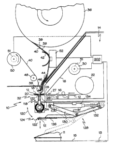
Fig. 1 illustrates, somewhat schematically, an apparatus, generally designated
10,
which weighs packages, prints labels, applies a security tag to the labels,
and applies the
labels to the packages. The apparatus 10 may be used with a conveyor 15 to
move the
packages into the appropriate position. However, a conveyor is not essential
to the invention,
and instead of a conveyor the items to be packaged may be simply placed in the
proper
position by an operator. Furthermore, the automatic label application is not
essential to the
3
CA 02283777 1999-09-09
WO 99/39980 PCT/US99/02365
invention, and the labels may be placed on the package by hand. Although these
various
embodiments may be used without departing from the scope of the invention, the
apparatus is
herein described with the use of a conveyor and a label application apparatus.
To initiate operation, packages 11 are loaded either manually or automatically
onto a
conveyor 15. Each of the packages is conveyed to a weighing station, where a
scale (not
shown) measures the package weight. Weighing can be performed on-the-fly or
with the
conveyor coming to a stop for a weighing operation, depending upon the design
and
performance characteristics of the unit. Alternately, an operator may place
the package
directly on the scale. The weight information is communicated to a controller
(not shown)
which may include a microprocessor. The controller computes the total price of
the package
by multiplying the price per unit weight by the measured weight of the
package. This
information, as well as other desired indicia, is then printed on a label 12
by printer 14.
The printer 14 prints upon blank labels 12 having one side coated with a
pressure-
sensitive adhesive. The labels 12 are carried on a strip of release material
16. Each label 12
has an adhesive side 18 and a non-adhesive printable side 20. The blank labels
are supplied
by a label supply roll 22. Print head 26 prints indicia on the printable side
20 of the label 12
as the labels are passed through the printer, and print roller 27 supports the
labels 12 as they
are printed. The printed labels may include such information as the weight,
price per unit
weight, total price, or a description of the packaged item, as well as
advertising or a UPC bar
code symbol. The print head 26 may be a thermal printer of the type having an
array of
individually energizabie heater elements which are selectively activated.
After printing by
print head 26, each label 12 is separated from the release material 16 by
drawing the release
material 16 under tension around a sharp bend provided by stripper bar 28. The
labels 12 are
transported through the printer 14 by a drive mechanism (not shown) connected
to take-up
hub 30 upon which the release material 16 is wound. The label 12 is then
discharged from
the printer unit at the label pickup station 32. When it is discharged, the
label 12 has its
adhesive side 18 facing toward the tag supply location 46 of the tags and is
received on the
label support means 34. While the invention is illustrated in the figure using
linered label
stock, those skilled in the art will appreciate that linerless label stock is
equally useful in
4
CA 02283777 1999-09-09
WO 99/39980 PCTNS99/02365
practicing the invention. Additionally, the tags of the present invention may
be applied to
any type of label which is applied to the package, including pre-printed
labels such as
predetermined price or bar code labels, or merchandising labels. Where pre-
printed label
stock is used in the invention, the print head 26 may not be used.
The security tag supply roll 36 comprises a plurality of electronic security
tags 38
adhesively attached to a backing 40. The tags 38 and backing 40 are passed
around a
semicircular guide 42 and a guide plate and stripper element 44. The guide
plate has a comer
46 at its bottom end. When the backing 40 and security tags 38 pass around the
corner 46,
the security tags 38 are stripped off of the backing 40, and applied to the
adhesive side 18 of
the label 12 below. The backing 40 then passes around a guide roller 48 and is
collected by
the take-up reel 50. In the present embodiment the tag falls to the adhesive
side 18 of the
label I2 below, but the plate 44 can also be located close enough to the label
18 that the tag is
directly applied. Once applied, the security tag 40 adheres to the adhesive
side 18 of the label
12. Preferably, the tag has an adhesive on one of its sides, and the tag is
applied such that the
adhesive side of the tag is facing outwardly. This helps to adhere the label-
tag combination
to the-package 11.
The take-up reel 50 is rotationally coupled to a motor (not shown) to drive
the rotation
of the supply roll 36. A detection mechanism 52 which typically employs a
light beam to
detect the leading edge of a security tag is provided upstream of the
stripping point to detect
the presence of a security tag 38. The detection mechanism 52 is used in
controlling the
motor to ensure that the supply roll 36 is advanced one security tag at a
time. In this manner,
once a label 12 is printed and ready to receive tag 38, rotation of the supply
roll 36 via take-
up reel 50 is coordinated with the detection mechanism 52 such that one
security tag 38 is
stripped from the backing material 40 and deposited on a label below.
It should be noted that the security tags 38 used with the invention may be
any of
those commonly used in the art which can be accommodated by the present
invention. These
include radio frequency and electromagnetic tags, commercially available from
Checkpoint
and Sensormatic. The apparatus of the present invention may be easily modified
to
CA 02283777 1999-09-09
WO 99/39980 PCT/US99/02365
accommodate various types of security tags. Additionally, the supply roll 36
may be replaced
with a cartridge-dispenser wherein the security tags 38 are ejected directly
from the cartridge
onto the label 12. In this embodiment neither side of the tag has an adhesive.
The apparatus 10 and the method of the invention fiuther provides for
selective
application of the security tags. It will not generally be necessary or
economic to apply tags
to all items labeled. Certain parameters may be used to determine which items
should receive
tags and when the parameters are not met the roll 36 is not advanced and the
security tag is
not applied. These parameters may include the type of product, total weight or
total price, or
even random application of the tags. Accordingly, the take-up reel 50 will
only advance the
supply roll to place a tag on a label when the controller has determined that
the item being
labeled requires a security tag. If the item does not require a tag, the take-
up reel will not
advance. If the take-up reel is advanced, it will continue doing so until the
leading edge of
the next tag has been detected at detector 52.
Once a label 12 has received a tag 38, the operator may remove the label 12
from the
label support means 34 and apply the label and tag to an article of
merchandise 11 by hand.
In this manner, the security tag is fixedly applied to the article, making it
secure from theft.
Additionally, the security tag is hidden from sight by the label. In an
alternate embodiment
the label and tag combination may be automatically applied to the package.
Several methods
for applying a label to a package are known in the art and may be used in
conjunction with
the present invention. For example, the label may be "blown" onto the package
by means of
pressurized air. A preferred embodiment for mechanically applying the label to
the package
employs a wand and is described in greater detail below.
In a preferred embodiment for applying the labels, the support means 34 has a
notch
or cut-out formed therein to receive a wand 118 having a vacuum cup I22 at its
distal end.
The wand 118, along with the label support means 34, receives the label 12
when it is
supplied by the printer. A vacuum retains the label 12 on the vacuum cup 122
at the end of
the wand 118. The wand 118 and cup 122 together comprise a label transporter.
Once a tag
has been applied to the label 34, the wand 118 pivots downwardly along arrow
120 to the
6
CA 02283777 2004-04-O1
WO 99/39980 PCT/US99/02365
dotted line position of the vacuum cup 122', where it arrives at a delivery
station 124. As the
label reaches the delivery station 124, it is positioned below a stripper
plate 126 of a label
applying assembly 128. In this position, the adhesive side 18 of the label is
facing
downwardly.
The label applying assembly 128 includes two pairs of pivotally-connected
scissor-
action arms 130 and 132 which are actuated by an air cylinder 134. When so
actuated, the air
cylinder 134 causes the stripper plate 126 to move downwardly, and thereby
remove the label
12 from the vacuum cup 122 and slap it onto a package 11. Timed vacuum means
(not
shown) applies a vacuum to the vacuum cup 122 at the time of pick-up of a
label, maintains
the vacuum "on" throughout its rotary travel to the transfer station, and
releases the vacuum
just as the cylinder 134 performs the transfer function.
Once the label 12 and tag 38 are applied to the package, the package 11 may be
manually removed or conveyed to the next station for further processing. While
the conveyor
1 S may be a stand-alone unit for carrying previously-wrapped packages the
labeler of the
present invention, the present invention may also be used in conjunction with
an automatic
wrapping machine such as is described in U.S. Pat. No. 4,813,211.
The conveyor is connected to such a wrapping machine at its exit end and
conveys
the product from the wrapping machine to the apparatus of the present
invention.
While the forms of apparatus herein described constitute a preferred
embodiment of
the invention, it is to be understood that the present invention is not
limited to these precise
forms and that changes may be made therein without departing from the scope of
the
invention.
7