Note: Descriptions are shown in the official language in which they were submitted.
CA 02283886 1999-09-13
WO 98/43446 PCT/SE98/00536
COivIlVIUNICATIN'G PACKET DATA WITH A MOBILE STATION
ROAMINiG WITHIN AN INCOMPATIBLE MOBILE NETWORK
BACKGROUND OF THE INVENTION
Technic I Field of the Invention
The present invention relates to packet data communication and, in
particular, to the communication of packet data, such as an Internet Protocol
(IP)
packet, toward a. mobile station roaming within an incompatible mobile
network.
Description of Related rt
Developrnents and improvements in mobile telecommunications networks
have enable mobile subscribers to communicate data, other than mere voice
data,
over a serving mobile telecommunications network. With a wide proliferation of
Internet and e-mail applications, mobile subscribers are able to access their
e-mail
messages or even browse or "surf" the Internet via their associated mobile
stations.
Accordingly, a mobile st:ation may function as data terminal equipment (DTE)
in
providing Interriet access or packet communication to an associated mobile
subscriber.
Unlike voice comnzunication, packet communication towards mobile stations
has not yet been fully standardized. As a result, a number of different
standards,
protocols, and/or schemes are available to provide packet communication with a
mobile station. Such differences in standards are especially true with respect
to
maintaining a panicular mobile station's current location and its registration
status.
A method and/or scheme for maintaining data associated with a particular
mobile
station and its location is referred to as "mobility management" and is needed
for
enabling a mobile station to freely travel or roam within a particular
network.
As an illustration, one such standard requires a separate mobility
management infrastructure and routing scheme for effectuating packet
comtnunication with a mobile station. Such a standard only utilizes a serving
mobile
switching center (MSC) and base station (BS) associated with an existing
mobile
CA 02283886 1999-09-13
WO 98/43446 PCT/SE98/00536
-2-
telecommunications network for establishing an over-the-air interface with the
mobile station located within a particular geographic area. Accordingly,
serving
mobile telecommunications nodes and devices, such as an MSC and BS, are only
utilized for the very last leg of the packet communication link with a mobile
station.
Such a standard is referred to as a Mobile IP Method (MIM) where a mobile
station
is assigned with a packet data network independent Internet Protocol (IP)
address.
The mobility management (MM) for keeping track of the current location of a
mobile station and for effectuating packet communication therewith are further
performed by separate packet data communications nodes, such as a home agent
(HA) and foreign agent (FA).
Another standard for communicating packet data utilizes existing mobile
telecommunications nodes and devices for effectuating mobility management
associated with a particular mobile station. A home location register (HLR) is
utilized within a conventional mobile telecommunications network for
maintaining
subscription data and for keeping track of a particular mobile station having
a
subscription therewith. Accordingly, each time a mobile station travels into a
geographic area being served by a new MSC, the new MSC communicates with the
associated HLR to inform the HLR of the mobile station's new location and to
retrieve requisite subscriber data associated with the newly registering
mobile
station. When an incoming voice call connection is requested toward the mobile
station, the serving mobile telecommunications network interrogates the HLR to
retrieve the location data previously provided by the serving MSC. Such data
are
then utilized by a serving Gateway Mobile Switching Center (GMSC), for
example,
to reroute the received voice call connection to the serving MSC.
Similarly for packet data communication, the existing HLR-MSC location
update mechanism and data as described above are also utilized by the packet
switching network to locate and to reroute packet data to the destination
mobile
station. Accordingly, in a manner similar to the HLR interrogation performed
by
the serving mobile telecommunications network for routing incoming voice
calls, the
packet data network similarly communicates with the HLR to identify the MSC
currently serving the destination mobile station. A gateway packet mobile
switching
CA 02283886 1999-09-13
WO 98/43446 PCT/SE98/00536
-3 -
center (GPMSC), for example, then reroutes packets to a Visited Packet Mobile
Switching Center (VPMSC) associated with the identified MSC. The serving MSC
and BS associateci with the VPMSC then establish a radio link with the
destination
mobile station to effectuate data packet communication in a conventional
manner.
Such a standard is commonly referred to as a traditional cellular mobility
method.
One example of a. packet data communications network utilizing such a standard
is
a Personal Digital Cellular Mobility Method network (PDCMM or more commonly
known as PMM network).
Even though thei-e are different types of data packet communications
standards, as long as a mobile station roams within a mobile
telecommunications
network utilizing a compatible packet communications standard, a corresponding
mobility management scheme communicates with appropriate devices and nodes to
enable the mobile station to access packet communication. However, when a
niobile
station belonging to a first mobile telecommunications network utilizing a
first
packet communications standard roams into a second mobile telecommunications
network utilizing a seconci packet communications standard, there is currently
no
mechanism for eilabling the mobile station to access packet data communication
while visiting the incompatible second packet telecommunications network. As a
result, for packet commuriication, a mobile station is currently restricted to
roam
within a compatible mobile telecommunications network.
Accordingly, there is a need for a mechanism to enable a mobile station to
roam from a first mobile telecommunications network utilizing a first packet
communications standard to a second mobile telecommunications network
utilizing
a second packet communications standard.
SUMMARY OF THE INVENTION
A system is disclosed for enabling a mobile station associated with a first
packet data network to rown within a second packet data network where the data
routing mechanisms utilized by the first and second packet data networks are
incompatible. To handle the situation where a mobile station associated with a
first
packet data network utilizing a first mobility management roams into a second
CA 02283886 1999-09-13
WO 98/43446 PCT/SE98/00536
-4-
packet data network utilizing a second mobility management, a foreign agent is
introduced into the second packet data network. The foreign agent connects
with
a gateway packet mobile switching center (GPMSC) associated with the second
packet data network and with a home agent associated with the first packet
data
network. An Internet Protocol (IP) tunnel is then established between the home
agent and the foreign agent enabling the home agent to directly deliver
incoming
packet data to the serving foreign agent. The GPMSC within the second packet
data
network further comprises an interface module for communicating with the
foreign
agent. The GPMSC further comprises a Point-to-Point Protocol (PPP) server for
effectuating a PPP connection with the roaming mobile station.
As another embodiment of the present invention, to handle the situation
where a mobile station associated with the second packet data network roams
into
the first packet data network, a home agent is introduced into the second
packet data
network. The foreign agent currently serving the roaming mobile station then
establishes a connection with the home agent and with a visited mobile
switching
center (VMSC) currently providing radio coverage for the mobile station
located
within a particular geographic area. More specifically, the foreign agent
establishes
an IP tunnel with the home agent.
The foreign agent associated with the first packet data network further
comprises a serving router for routing packet data communicated with the
roaming
mobile station. The foreign agent in accordance with the teachings of the
present
invention also includes a Mobile IP Client Emulator (MICE).
BRIEF DESCRIPTION OF THE DRAWINGS
A more complete understanding of the method and apparatus of the present
invention may be had by reference to the following detailed description when
taken
in conjunction with the accompanying drawings wherein:
FIGURE 1 is a block diagram of a packet data network utilizing a Personal
digital cellular Mobility Method (PMM) and illustrating the communication of
packet data with a mobile station;
CA 02283886 1999-09-13
WO 98/43446 PCT/SE98/00536
-5-
FIGURE 2 is a signal sequence diagram illustrating the handover of a mobile
station within a network: utilizing the Personal digital cellular Mobility
Method
(PMM);
FIGURE 3 is a block diagram of a packet data network utilizing a Mobile IP
Method (MIM) and illustrating the communication of packet data with a mobile
station;
FIGURE 4 is a signal sequence diagram illustrating the handover of a mobile
station within a r-etwork utilizing the Mobile IP Method (MIM);
FIGURE 5 is a block diagram of two different packet data networks
illustrating the roaming of a mobile station from a first packet data network
to a
second packet data network in accordance with the teachings of the present
invention;
FIGURE 6 is a signal sequence chart illustrating the roaming of a mobile
station from the first packet data network to the second packet data network;
FIGURE 'I is a block diagram of the second packet data network illustrating
the handover of tr,e mobile station associated with the first packet data
network from
a first visited mobile switching center (VMSC) to a second VMSC;
FIGURE 8 is a block diagram of two different packet data networks
illustrating the roaming of a mobile station from the second packet data
network to
the first packet data network in accordance with the teachings of the present
invention;
FIGURE S> is a signal sequence chart illustrating the roaming of the mobile
station from the second packet data network to the first packet data network;
and
FIGURE 10 is a block diagram of the first packet data network illustrating
the handover of a mobile station associated with the second packet data
network
from a first visited mobile switching center (VMSC) to a second VMSC.
DETAILED DESCRIPTXON OF THE DRAWINGS
FIGURE 1 is a block diagram of a packet data network 10 utilizing a
Personal Digital Cellular Mobility Method (PDCMM, hereinafter referred to as a
CA 02283886 1999-09-13
WO 98/43446 PCT/SE98/00536
-6-
PMM network) and illustrating the communication of packet data with a mobile
station 20.
It is in connection with this PMM network that the preferred embodiments
of the present invention will be described. However, as the system and method
of
the present invention are applicable with any network utilizing a traditional
cellular
mobility method, it will be understood that the description of the present
invention
in the context of the PMM network provided herein is by way of explanation of
the
present invention in the context of a packet data network utilizing the
traditional
cellular mobility method rather than of limitation of the scope of the
invention.
A plurality of base stations (BSs) 30 provide radio coverage over a plurality
of geographic areas. A particular BS 30 then connects to an associated visited
mobile switching center (VMSC) 40 for routing and processing communicated
data.
In case the communicated data is normal voice data, the VMSC 40 communicates
with an associated backbone network 15 to communicate the voice data with a
specified destination terminal. On the other hand, in case the communicated
data
represent Internet Protocol (IP) data or packet data, the VMSC 40 instead
communicates with a visited packet mobile switching center (VPMSC) 80. The
VPMSC 80 then communicates with the associated backbone network 15 to
communicate with a specified destination node.
Whenever a particular mobile station travels into a particular geographic
area, a base station (BS) 30 serving that geographic area transmits
identification data
informing the mobile station of the current location. Utilizing such
identification
data, the mobile station 20 realizes that it has traveled into a new
geographic area
being covered by a new visited mobile switching center (VMSC) 40 and performs
a registration. Therefore, an associated mobile identification number (MIN,
such
as a Mobile Subscriber Integrated Service Digital Network - MSISDN number,
International Mobile Subscriber Identity - IMSI number, etc.,) is transmitted
to the
serving base station 30. The serving base station 30, in turn, forwards the
received
registration request to the VMSC 40 serving that geographic area. Utilizing
the
received mobile identification number, the VMSC 40 then identifies a home
location
register (HLR) 50 associated with the mobile station 20. The HLR 50 is a
CA 02283886 1999-09-13
WO 98/43446 PCT/SE98/00536
-7-
centralized database associated with the home network for storing subscription
data
representing the :mobile station 20 and for maintaining location data
reflecting the
mobile station's current location and registration status. Furthermore, the
HLR 50
associated with th! PMM network further stores data correlating the received
mobile
identification nuniber with a corresponding Internet Protocol (IP) address
assigned
to the mobile station 20.
As a result, a location update signal is transmitted from the serving VMSC
40 to the associated HLR 50 (signal link 60) through the backbone network 15.
The
HLR 50 authenticates the mobile station 20 and provides requisite subscriber
data
back to the VMS(: 40. The serving VMSC 40 may also be associated with a local
database, such as a Gatevvay Location Register (GLR, not shown in FIG. 1), for
storing data associated with, all mobile stations currently traveling within
its coverage
area and for comrnunicating with associated HLRs.
Packet data addressed to the IP address associated with the mobile station 20
is transmitted from an origination point. Such an origination point may be
within
the same serving PMM network 10 or from an external network. For exemplary
purposes, packet data originated towards the mobile station from an external
node
are illustrated herein. Within the PMM network 10, each associated mobile
station
is assigned wiith a PN[M network dependent IP address. When packet data
20 addressed to an associated PMM allocated IP address is routed, it is first
delivered
to a gateway packet mobile switching center (GPMSC) 70 serving the PMM network
10. The GPMSC'70 therefore serves as a gateway for receiving all incoming
packet
data with IP address associated therewith.
The GPMSC 70 then performs an interrogation with the HLR 50 to
determine how to route the received packet data. As described above, the HLR
50
retains information regarding the current location of the mobile station. The
GPMSC 70 provides the HLR 50 with the received IP address. Utilizing the
received IP address and correlated mobile identification number, the HLR 50 is
able
to ascertain the current location of the traveling mobile station 20. The HLR
50
then returns routing instructions to the requesting GPMSC 70. Such routing
instructions include, for example, an Internet Protocol (IP) address
representing a
CA 02283886 1999-09-13
WO 98/43446 PCT/SE98/00536
-8-
visited packet mobile switching center (VPMSC) 80 associated with the serving
VMSC 40. The GPMSC 70, in tum, establishes an IP tunnel 90 with the identified
VPMSC 80. The GPMSC 70 effectuates the IP tunnel 90 by encapsulating the
received IP packet data addressed to the mobile station 20 within another IP
packet
addressed to the identified VPMSC 80. The mobile identification number is
further
encapsulated within the transmitted IP packet. Accordingly, the received
packet
data is rerouted to the VPMSC 80 associated with the VMSC 40 currently serving
the traveling mobile station 20. The VPMSC 80 then extracts the encapsulated
original IP packet and identifies the mobile station using the provided mobile
station
identification number. The extracted IP packet data are then forwarded to the
serving VMSC 40 and delivered to the mobile station 20 by way of radio-
interface
100. Accordingly, packet data communication with the mobile station 20 is
effectuated.
As illustrated, the HLR 50 is interrogated or queried for routing and
delivering incoming voice calls as well as packet data within the PMM network.
The serving PMM data network 10 therefore utilizes an existing
telecommunications
node, such as an HLR, to maintain and to locate a particular mobile station
for
routing packet data thereto. Such an HLR is further utilized for effectuating
a
handover of a mobile station from a first VMSC to a second VMSC within the
PMM network.
For originating packet data communication by the mobile station 20, after
performing the location update as described above, the mobile station 20
requests
packet data communication to the VPMSC 80 through the serving VMSC 40. The
mobile station 20 then originates packet data to the established VPMSC 80
which,
in tum, delivers the data to a specified destination node via the connected
backbone
network 15.
Reference is now made to FIG. 2 illustrating the handover of a mobile station
within the PMM network. A mobile station may also be equipped with or be
associated with a data terminal equipment (DTE). As described above, the GPMSC
70 initially receives incoming packet data 100. The GPMSC 70 thereafter
performs
an HLR interrogation 110 with the associated HLR 50 to acquire routing
CA 02283886 1999-09-13
WO 98/43446 PCT/SE98/00536
-9-
instructions. The HLR 50 returns an identifying address 120 representing the
VPMSCI 80 currently serving the mobile station 20. Alternatively, the serving
HLR 50 may also return a roaming number representing the serving VMSC1 40.
The GPMSC 70, in turn, may identify the VPMSC1 80 associated with the
determined VMSC1 40.
Utilizing the rec:eived identifying address, an IP tunnel 130 is then
established between the VPMSCI 80 and the GPMSC 70. The VPMSCI 80 then
delivers the packet data 140 to the VMSCI currently serving the mobile station
20.
The received packet data are then forwarded 150 to the BS 1 30 currently
serving that
geographic area, such as a cell or location area. By way of radio interface
160, the
received packet clata are then communicated with the traveling mobile station
20.
When the mobile station 20 travels out of the current geographic area being
served by the VMSCI 40 and travels into a new geographic area being served by
a
new VMSC2 45, the mobile station 20 performs a new location update. A packet
communication registration signal 170 is then transmitted to a new BS2 serving
the
new geographic ai-ea. The BS2 then forwards the registration request signal
180 to
the connected VMSC2 45. The VMSC 45 then similarly forwards the packet
communication registration signal 185 to the associated VPMSC2 85. The VPMSC2
85 then performs a location update 190 with the HLR 50 to inform the HLR 50 of
the mobile statiori's new location. The HLR 50, in turn, informs the GPMSC 70
with a new identifying address 200 representing the new VPMSC 85 associated
with
the new serving VMSC2. The GPMSC 70 then utilizes the new address to establish
a new IP tunnel 210 between the GPMSC 70 and the newly identified VPMSC2 85.
Subsequently received data are then rerouted to the new VPMSC2 85 via the new
IP tunnel 210. The VPMSC2 85 then delivers the received data 220 to the
traveling
mobile station 20 i.n a similar manner as described above. As a result, a hand
over
of the mobile station from the first VMSC1 40 to the second VMSC 45 is
effectuated.
Reference is now made to FIG. 3 illustrating a different type of packet data
network 300 utilizing a Mobile IP Method (MIM, hereinafter referred to as an
MIM
network) to com;municate packet data with a mobile station. Within the MIM
CA 02283886 1999-09-13 3' % u J 5 -3 6
The Swedish Patent Of; :: - 1 4-06- 1999
P('.T International Applicai;. , I
-10-
network 300, packet data communication is effectuated via a home agent (HA)
320
and a foreign agent (FA) :310. Each VMSC 40 or geographic area is associated
with
a foreign agent (]FA) 310 for effectuating packet data communication. Each FA
310
is further equipped with a serving router for routing received packet data to
appropriate destination nades. The mobile station 20 is then associated with a
home
agent (HA) 320. Furthermore, a mobile station 20 associated with the MIM
network
300 is assigned vvith an II' address representing the associated HA 320. Such
a HA
can be located either within the MIM network 300 as illustrated in FIG. 3 or
within
an external network (not shown in FIG. 3) connected to the MIM network.
Accordingly, unlike the PMM network, an IP address representing a particular
mobile station associated with the MIM network 300 does not necessarily
identify
the MIM network 300.
Registrati.on of ainobile station within the MIM network is performed in a
conventional manner. The mobile station 20 performs a registration request
with
a BS 30 serving a current geographic area. The BS 30 forwards the request to
the
connected VMSC 40. The VMSC 40 then performs a location update with an
associated HLR 50 to infbrm the HLR 50 of the mobile station's current
location.
This location update enables an incoming voice connection to be effectuated
towards
the traveling molbile station as fully described above.
However, unlike The PMM network, the HLR 50 within the MIM network
300-does not retain data correlating a particular mobile identification number
with
a corresponding IP address. This is because, as described above, each mobile
station within the: MIM network 300 is assigned with an MIM network
independent
IP address. Accordingly, the HLR 50 associated with the MIM network 300 has no
control over the associated IP addresses and their correlation with mobile
stations.
The serving MIM network itself is not able to initiate a data session with an
associated mobile station. As a result, in order to cornmunicate IP packets or
data,
the serving MIM network needs to wait until the mobile station 20 first
initiates a
data session. The mobile station 20 initiates a data session by requesting
packet data
communication with the serving BS 30. The BS 30 then forwards the request
through the serving VMSC 40 to an associated foreign agent and serving router
AMENDED SHEET
CA 02283886 1999-09-13
WO 98/43446 PCT/SE98/00536
-11-
(FA/SR) 310. The FA/SR 310 then analyzes the IP address transmitted by the
traveling mobile station 20 and determines a home agent 320 associated
therewith.
The HA 320 is a packet data communication node for keeping track of the mobile
station's current location and for performing gateway function for receiving
and
routing incoming packet data. The FA 310 then communicates with the identified
HA 320 to establish an IP tunnel 330 therebetween.
Incoming packet data addressed to the IP address associated with the mobile
station 20 are first delivered to the HA 320 associated to the mobile station
20. The
HA 320 then reroutes the received packet data to the connected FA/SR 310 by
similarly encapsulating the received IP packet within another IP packet
addressed
to the FA/SR '310. The encapsulated IP packet is then transmitted over the
established IP tunnel 330. The FA/SR 310 then extracts the original packet
data
from the received IP packet and forwards the extracted data through the
serving
VMSC 40 to the mobile station 20 by way of radio-interface 100 as described
above.
As illustrated above, the only mobile telecommunications nodes utilized for
effectuating the communication of packet data with a mobile station are the
VMSC
40 and base station 30 serving that particular geographic area. Accordingly,
the
VMSC 40 and EIS 30 are used as the very last leg of the communication link to
deliver packet data via over-the-air interface 100 toward the mobile station
20.
Mobility management (MM) for maintaining the current location of a mobile
station
20 and for reroutiizg packet: data to the traveling mobile station 20 are
performed via
separate packet data communications nodes, such as a home agent (HA) and a
foreign agent (FA).
Reference is now made to FIG. 4 illustrating the handover of a mobile station
20 within an MIIN network. As described above, the mobile station 20 traveling
within a particular geographic area requests packet communication by
transmitting
a packet communication request 400 towards the serving BS1 30. The BS1 30
relays the request 410 to the connected VMSC1 40. The VMSCl 40 determines that
this request is associated with packet data communication and establishes an
IP
communication link 420 with the foreign agent / serving router (FA/SR1) 310
serving that particular geographic area. As a result, a Point-to-Point
Protocol (PPP)
CA 02283886 1999-09-13
WO 98/43446 PCT/SE98/00536
-12-
connection is established between the mobile station 20 and the FA/SR1 310.
The
FA/SR1 310 then communicates with a home agent (HA) 320 associated with the
traveling mobile station 20 and effectuates an IP tunnel 440 therebetween.
Packet
data delivery 450 over the IP tunnel 440 is thereafter effectuated.
When the mobile station 20 travels out of the current geographic area being
served by the VMSC1 40 and travels into a new geographic area being served by
a
new VMSC2 45, the mobile station again requests a new packet communication
request 460 to a BS2 35 currently providing radio coverage over the new
geographic
area. The BS2 35 similarly forwards the request 470 to the VMSC2 45 serving
that
particular geographic area. The VMSC2 45 then establishes a link with an
associated FA/SR2 315. Accordingly, a new PPP connection 480 is established
between the mobile station 20 and the new FA/SR2 315. The FA/SR2 315 then
contacts the HA 320 associated with the mobile station and establishes a new
IP
tunnel 500 therebetween. Subsequently received incoming packet data 510 are
then
delivered to the VMSC2 45 via the new IP tunnel 500. As a result, the mobile
station 20 is handed over from the VMSC1 40 and FA/SRl 310 to the new VMSC2
45 and FA/SR2 315.
As illustrated above in FIGS. 1 through 4, mobility management and
handover mechanisms within the PMM network and MIM network are different and
incompatible with each other. As a result, a mobile station associated with a
PMM
network is not able to roam into an MIM network and receive packet data
therein.
Similar incompatibility exists for a mobile station associated with an MIM
network
and roaming within a PMM network. Furthermore, while maintaining a
communication link, the mobile station can not be handed-over over a plurality
of
VMSCs within a visiting network.
Reference is now made to both FIGS. 5 and 6 illustrating a mobile station
20 associated with an MIM network 300 roaming within a PMM network 10 in
accordance with the teachings of the present invention. The roaming MIM mobile
station 20 is associated with a home agent (HA) 320. As previously described,
such
a HA can be located within the MIM network 300 or within an external data
network.
CA 02283886 1999-09-13
WO 98/43446 PCT/SE98/00536
-13-
In order to deliver incoming packet data towards the mobile station, the HA
320 needs a corresponding foreign agent (FA) located within the visited
geographic
area. However, since conventional PMM network 10 does not include a foreign
agent, no IP tunnel can be established between the HA 320 and the PMM network
10. Therefore, in. accordance with the teachings of the present invention, a
foreign
agent (FA) 310 is introduced into the PMM network 10 to effectuate an IP
tunnel
between the home agent (HA) 320 and the PMM network 10.
When the MIM mobile station 20 roams into a new geographic area within
the PMM network 10, the mobile station 20 performs a registration in a
conventional manner by transmitting a location registration request 630 over
the air-
interface 100. The mobile station 20 may further be associated with a data
terminal
equipment (DTE) 20A. The base station (BS) 30 receives the requests and
forwards
it to the connectecl VMSC 40. The VMSC 40, in turn, performs an authentication
procedure by transmitting a Subscriber Authentication Information Retrieval
Request
640 to an associated gateway location register (GLR, also known as a visitor
location register VLR) 620. The GLR 620, in turn, transmits an Inter-
networking
Authentication Information Retrieval Request signal 650 to a home location
register
(HLR) 50 associated with the registering mobile station 20. The associated HLR
50
authenticates the subscriber and informs the GLR 620 with necessary
authentication
data via lnter-wor=king Authentication Information Retrieval Response signal
660.
Such data include 1:he authentication keys associated with the mobile station
20. The
GLR 620, in turn, informs the results 670 back to the requesting VMSC 40. The
VMSC 40 then transmits an Authentication Request signal 680 to confirm the
authentication data with the mobile station 20. In response, the mobile
station 20
provides the requested authentication data via an Authentication Response
signal
690. After verifying the received data and confirming the mobile station 20, a
Location Registration Acknowledgment signal 700 is transmitted to the mobile
station 20 by way of air-interface 100. The mobile station 20 is now
registered to
access the serving mobile telecommunications network for normal mobile
services
(i.e., voice call connection).
CA 02283886 1999-09-13
WO 98/43446 PCT/SE98/00536
-14-
After establishing the authentication procedure, the associated DTE 20A
enters packet mode and instructs the mobile station 20 to transmit a Packet
Communication Registration Request signal 710 to the VPMSC 80 through the
VMSC 40. Such a separate request is necessary to further enable the mobile
station
20 to communicate packet data instead of normal voice data. The VPMSC 80 may
further communicate with the associated GLR 620 to authenticate the mobile
station
20 for packet data communication (not shown in FIGS. 5 and 6). In return, the
VPMSC 80 may also transmit a Packet Authentication Request signal 720 to the
mobile station 20. The mobile station 20 may then respond with a Packet
Authentication Response signal 730. After verifying that the mobile station 20
is
authenticated to utilize packet communication, a Packet Communication
Registration
Response signal 740 is provided back to the mobile station 20. The mobile
station
then enters packet mode.
For mobile stations belonging to the MIM network 300 and currently
15 traveling within the PMM network 10, the VPMSC 80 establishes an IP tunnel
750
with the newly created FA 310. More specifically, the VPMSC 80 creates a first
IP tunnel 750 with a gateway packet mobile switching center (GPMSC) 70 serving
the PMM network 10. The GPMSC 70, in turn, interfaces with the FA 310. As
described above, since the mobile station 20 is associated with the MIM
network
20 300, a home agent (HA) 320 associated with mobile station 20 receives all
incoming
packet data addressed towards the mobile station 20 currently roaming within
the
PMM network. Since the HA 320 requires a foreign agent (FA) to establish an IP
tunnel and to communicate received packet data therebetween, the new foreign
agent
310 as described above is introduced within the PMM network 10 in accordance
with the teachings of the present invention.
The DTE 20A connected to the mobile station 20 then performs a PPP
establishment procedure 760 towards the FA/GPMSC 310/70. The DTE then sends
a Mobile IP Agent Solicitation message 770 to effectuate an IP connection with
the
home network. The new FA node 310 of the PMM network 10 responds with an
Mobile IP Agent Advertisement message 780. The DTE then sends a Mobile IP
Registration Request message 790 to the FA 310. The FA 310 then identifies the
CA 02283886 1999-09-13
WO 98/43446 PCT/SE98/00536
-15-
HA 320 associated with the roaming mobile station 20 and forwards the message
800 to the identified HA 320. The HA sends a Mobile IP Registration Reply
message 810 back to the FA/GPMSC 310/70 and further establishes a second IP
tunnel 755 with the serving FA 310. The FA/GPMSC 310/70 then forwards such
a message 820 to the DTE 20A. A data delivery between the HA 320 and the DTE
20A is effectuate thereafter. For example, for incoming data packets 830
addressed
towards the DTE 20A, the packets are initially received by the HA 320 and
routed
to the DTE 20A via the second IP tunnel 755 and the first IP tunnel 750. For
outgoing data packets 900 originated from the DTE 20A, the packets are first
routed
by the first IP tunnel 750 towards the FA 310 and then, for example, to an
appropriate exterrial network 900.
The GPMSC 70 associated with the PMM network 10 further includes an
interface module 600 for interfacing and communicating with the newly
introduced
FA 310. Furthermore, in order to facilitate the DTE's PPP establishment
request,
the GPMSC 70 is further equipped with a PPP server 610 in accordance with the
teachings of the present invention.
Accordingly, by introducing the foreign agent (FA) 310 within the PMM
compatible network 10, the home agent (HA) 320 located with the home MIM
network 300 is able to establish an IP tunnel with the new FA 310 and
effectuate
packet data communication with the mobile station 20 roaming within an
otherwise
incompatible network.
FIGURE 7 is a block diagram of the PMM data packet network 10
illustrating the hand over of a mobile station 20 associated with the MIM
network
from a visited mobile switching center 1(VMSC1) 40A to a VMSC2 40B in
accordance with the teachings of the present invention. As described in detail
in
FIGS. 5 and 6, the mobile station 20 associated with the MIM network roams
into
the PMM network 10 and is being served by the VMSC1 40A. An IP tunnel 750A
is established between a visited packet mobile switching center 1(VPMSC) 80A
associated with the serving VMSC1 40A and the gateway packet mobile switching
center (GPMSC) 70 as described above. The GPMSC 70 then interfaces with a
foreign agent (FA) 310 for communicating packet data with an associated home
CA 02283886 1999-09-13
WO 98/43446 PCT/SE98/00536
-16-
agent (HA) over yet another IP tunnel 800. When the mobile station 20 travels
out
of the current VMSCl coverage area and roams into a new geographic area being
covered by the VMSC2 40B, the mobile station 20 again performs a location
update
100 in a similar manner. A base station 2 (BS2) 30B providing radio coverage
for
that particular geographic area then receives the location update signal and
forwards
it to the associated VMSC2 40B. The VMSC2 40B then communicates with the
GLR 620 to authenticate the new mobile station 20 and to inform the GLR 620 of
the mobile station's new location (signal 940). The GLR 620, realizing that
this
mobile station is roaming from the VMSCI coverage area to the VMSC2 coverage
area and needs to be handed over to the VMSC2, informs the GPMSC 70
accordingly (signal 960). The GPMSC 70, in turn, identifies a new VPMSC2 80B
associated with the VMSC2 40B and establishes a new IP tunnel 750B
therebetween.
The existing IP tunnel 750A between the GPMSC 70 and the previous VPMSCI
80A is released. However, the IP connection 800 between the HA (not shown in
FIG. 7, refer to FIG. 5) and the FA 310, and a connection between the FA 310
and
the GPMSC 70 remain unchanged. As a result, subsequently communicated packet
data are effectuated over the newly established IP tunnel 750B and delivered
to the
mobile station 20 via the new VMSC2 40B. A handover from the first VMSC1 40A
to the second VMSC2 40B is successfully performed.
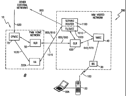
Reference is now made to both FIGS. 8 and 9 illustrating a mobile station
20 associated with a PMM network 10 roaming into an MIM network 300 in
accordance with the teachings of the present invention. As fully described in
FIGS.
3 and 4, the MIM network 300 serving the roaming mobile station 20 utilizes a
foreign agent (FA, not shown in FIG. 8, refer to FIG. 3) to route packet data
with
an associated mobile station. The FA then communicates with a home agent (HA)
associated with the traveling mobile station and located within the home
network to
establish an IP tunnel therebetween. However, the PMM network 10 associated
with a PMM mobile station 20 does not include a home agent (HA) for serving
the
roaming mobile station 20. Instead, the PMM network utilizes a GPMSC (not
shown, refer to FIG. 1) and an HLR 50 for effectuating mobility management and
for receiving incoming packet data addressed to the roaming mobile station.
CA 02283886 1999-09-13
WO 98/43446 PCT/SE98/00536
-17-
Furthermore, the signaling sequences utilized by the roaming mobile station
are
incompatible with the MIM network. The MIM network 300 expects the mobile
station to perforrn a Mobile IP Registration before transmitting user data
thereto.
However, a standard PMM associated mobile station does not perform such a
registration. Therefore, in order to resolve such an incompatibility, in
accordance
with the teachings of the present invention, a new home agent (HA) 320A is
introduced into the PMM network 10 for purposes of serving a PMM network
associated mobile station currently roaming within the MIM network 300.
The registration of the mobile station 20 associated with the PMM network
and roaming within the MIM network 300 is performed in a conventional manner
as fully describeci above. For example, the mobile station 20 roams into a new
geographic area 'within the MIM network 300 and performs a registration by
transmitting a location registration request 630 over the air-interface 100.
The base
station (BS) 30 receives the request and forwards it to the connected VMSC 40.
The
VMSC 40, in turn, performs an authentication procedure by transmitting a
Subscriber Authentication Information Retrieval Request signal 640 to an
associated
gateway location register (GLR, also known as a visitor location register VLR)
620.
The GLR 620, in turn, transmits an Inter-networking Authentication Information
Retrieval Request signal 650 to a home location register (HLR) 50 associated
with
the registering rriobile station 20. The associated HLR 50 authenticates the
subscriber and informs the GLR 620 with necessary authentication data via an
Inter-
working Authentication Information Retrieval Response signal 660. Such data
include the authentication keys associated with the mobile station 20.
Additional
subscription data, such as special subscriber feature data, may further be
down-
loaded to the GLR. 620.
The GLR 620, in tum, informs the results 670 back to the requesting VMSC
40. The VMSC 4CI then transmits an Authentication Request signal 680 to
confirm
the authentication data with the mobile station 20. In response, the mobile
station
20 provides the requested authentication data via an Authentication Response
signal
690. After verifying the received data and confirming the mobile station 20, a
Location Registration Acknowledgment signal 700 is transmitted to the mobile
CA 02283886 1999-09-13
WO 98/43446 PCT/SE98/00536
-18-
station by way of air-interface 100. The mobile station 20 is now registered
to
receive normal mobile service.
The DTE 20A associated with the mobile station 20 enters packet mode and
instructs the mobile station 20 to transmit a Packet Communication
Registration
Request message 710 over the air-interface 100. Such a separate packet request
is
necessary because the previously performed registration by itself does not
authenticate the mobile station 20 for packet communication. After
authenticating
the mobile station for packet communication with associated GLR (not shown in
FIGS. 8 and 9), the VMSC 40 sends a Packet Authentication Request signal to
the
requesting mobile station (not shown in FIGS. 8 and 9). The VMSC 40 may also
receive Mobile IP parameters from the associated GLR. After confirming the
authentication, since the mobile station 20 is a PMM associated mobile
station,
instead of communicating with a conventional foreign agent (FA), the VMSC 40
transmits a Tunnel Establishment Request 1010 to a newly introduced packet
data
communication function known as a Mobile IP Client Emulator (MICE) 1000. This
function may reside within a service router. The transmitted tunnel request
further
includes the Mobile IP parameters received from the GLR. The MICE 1000, in
turn
acting as a foreign agent, sends a Mobile IP Registration Request 800 to the
newly
introduced HA 320A of the home network, emulating a DTE supporting Mobile IP
in accordance with the teachings of the present invention. The retrieved
Mobile IP
parameters are further communicated during this process. The HA 320A responds
with a Mobile IP Registration Reply message 810. As a result, an IP tunnel
1015
between the newly introduced HA 320A associated with the PMM network and the
MICE 1000 associated with the MIM network is established. The MICE 100 then
transmits a Tunnel Establishment Reply signal 1020 to the VMSC 40. The VMSC
40 then sends a Packet Communication Registration Response signal 740 to the
mobile station 20. Upon receiving the acknowledgment signal, the mobile
station
20 enters packet mode. The associated DTE 20A then performs a link
establishment
830 towards the MICE 1000 in accordance with the pre-defined PMM procedures.
The newly introduced MICE 1000 functions as a foreign agent (FA) for the
mobile station 20 associated with the PMM network 10 and traveling within the
CA 02283886 1999-09-13
WO 98/43446 PCT/SE98/00536
-19-
MIM network 300. Since the IP address associated with the mobile station 20
also
represent the home PMM network 10, all incoming packet data addressed toward
the mobile station 20 are first received by the gateway packet mobile
switching
center (GPMSC) 70 located within the home PMM network 10. After
communicating with the associated HLR 50, instead of establishing an IP tunnel
with
a visited packet mobile switching center (VPMSC, refer to FIG. 1), the GPMSC
70
realizes that the mobile station 20 is currently traveling within the MIM
network 300
and instead establishes an IP tunnel 1030 with the newly introduced HA 320A.
The
HA 320A then delivers the received packet data towards the MICE 1000 over the
established IP tunnel 1015. The MICE 1000 then extracts the encapsulated
packet
data and delivers the extracted data to the VMSC 40 currently serving the
mobile
station 20.
The MICE 1000 is further associated with a serving router 1100. For
outgoing packet data originated by the roaming mobile station 20, there is no
need
for the packet data to be delivered to the home network 10. Instead, the
serving
router 1100 associated with the MICE 1000 connects to other external networks,
if
necessary, and transmits the received data packets 900 directly.
FIGURE 10 is a block diagram illustrating the hand over of a mobile station
associated with a PMM network being handed over from a VMSC1 40A to a
VMSC2 40B withiin a visited MIM network 300 in accordance with the teachings
of
the present inventicin. In a manner as described in FIGS. 8 and 9, the mobile
station
20 registers with and is being served by the VMSCl 40A. When the mobile
station
20 travels out of the VMSC1 coverage area and travels into a new geographic
area
being served by the new VMSC2 40B, the mobile station 20 again performs a
packet
communication registration therewith. The transmitted registration signal is
received
by a new BS2 30B providing radio coverage for that particular geographic area
and
forwarded to the associated VMSC2 40B. In a conventional manner as described
above, the VMSC2 40B then communicates with the GLR 620 to authenticate the
mobile station (sigrial 1140). The GLR 620, realizing that the mobile station
20 is
a PMM associateci mobile station, accordingly informs the VMSC2 40B. The
VMSC2 40B then issues a tunnel establishment request to the MICE 1000. The
CA 02283886 1999-09-13
WO 98/43446 PCT/SE98/00536
-20-
MICE 1000 then determines that the new VMSC2 40B is attempting to serve the
roaming mobile station 20, interrupts the current IP connection 1130A with the
existing VMSC1 40A, and establishes a new IP connection 1130B with the new
VMSC2 40B. All subsequently received packet data are then delivered to the new
VMSC2 40B over the newly established IP connection 1130B. The existing IP
tunnel 1120 between the MICE 1100 and the HA remains unchanged. As a result,
a handover from the VMSCI 40A to the VMSC2 40B within the MIM network 300
is effectuated.
Although preferred embodiments of the method and apparatus of the present
invention have been illustrated in the accompanying Drawings and described in
the
foregoing Detailed Description, it will be understood that the invention is
not limited
to the embodiments disclosed, but is capable of numerous rearrangements,
modifications and substitutions without departing from the spirit of the
invention as
set forth and defined by the following claims.