Note: Descriptions are shown in the official language in which they were submitted.
CA 02283997 1999-09-10
WO 98/46179 PCT/US98/00345
FLEXIBLE NON-CONTACT WOUND TREATMENT DEVICE
TECHNICAL FIELD
This invention relates to a wound treatment device and, in particular, to a
wound
treatment device having a substantial portion of a wound cover that is in non-
contact with
a wound and capable of delivering heat to the wound. More particularly, the
wound
treatment device includes a flexion joint that maximizes the ability of the
wound treatment
device to adapt to the contours and movements of a human body.
BACKGROUND ART
A novel mode of wound treatment is disclosed in detail in published PCT
Applications WO 94/00090 and WO 96/15745, both owned in common with this
application. This new treatment employs a non-contact wound treatment device
that covers
a wound, forming a treatment volume about and over the wound. An embodiment of
such
a wound treatment device may be characterized in having a plurality of parts,
three of
which are useful for the purpose of description. These three parts are an
attachment
portion, a wound treatment portion, and a transition portion. Each portion
serves a
1 S respective function.
The attachment portion connects and retains the wound treatment device on the
skin
of a person. The wound treatment portion typically includes a standoff that
rises above the
person's skin surface, and a wound cover that spans an open portion of the
standoff.
Together, the standoff and wound cover define a wound treatment volume and a
wound
treatment area onto which the wound treatment volume is projected.
The transition portion connects the attachment portion to the wound treatment
portion. An important function of the transition portion is to adapt the wound
treatment
device to the contour of the portion of a person's body where the device is
mounted and to
movements of the person's body that deform the wound treatment device in situ.
In this
regard, an important function of the transition portion is the accommodation
of patient
motion by the compliance of the transition portion.
.. . 1,.~""-.:fr,~.
CA 02283997 1999-09-10
SUBSTITUTE PAGES P.CT/IJS98/00345
. . ,
, .
~ s v a
2
Achievement of this important function of the transition portion is challenged
by the need to maintain the orientation of the wound cover in the wound
treatment
portion - both in aspect and location - with respect to the wound being
treated. The
orientation of the wound cover is difficult to maintain when the wound
treatment
device is mounted on a highly curved part of a body. While the wound treatment
devices disclosed in the referenced PCT applications exhibit excellent
adaptability
in a surface that is parallel to the surface of the body portion where the
wound
treatment device is mounted, there is impairment of adaptability and
disturbance of
the orientation of the wound cover due to limited flexibility in the direction
of a Z
axis that is perpendicular to the surfaces. If the transition portion is
substantially
perpendicular to the attachment portion, it may buckle in response to body
motion or
contour and collapse the standoff in the wound treatment portion. The collapse
of the
standoff of course alters the orientation of the wound cover with respect to
the
wound, possibly reducing the effectiveness of the wound treatment device.
Z axis conformability is especially important for a wound treatment device
used on a portion of a person's lower leg. The lower leg has a very tight
radius of
curvature. Therefore, when a three-dimensional wound treatment device is
curved
around a lower leg, substantial stress results that may result in deformation
of the
shape of the wound treatment device, in some cases even causing the wound
cover
to contact the wound.
European patent application A- 0 355 186 discloses a wound irrigation device
with a collar mounted to an adhesive label by a flexible sheet. U.S. Patent
No.
5,80,346 concerns a protective covering for a lesion having a frame that
adheres to
the skin surrounding the lesion. U.S. Patent No. 4,468,227 concerns a wound
drainage pouch with a bottom layer that can be adapted to fir around a wound.
DISCLOSURE OF INVENTION
The overall flexibility of a wound treatment device is enhanced by an
invention based upon the inventors' critical realization that provision of a
membrane
in the transition portion that connects the wound treatment portion to the
attachment
P:UUGUSTIMl53903.AMi
Al~kc.';DCD SHE~T-
CA 02283997 1999-09-10
SUBSTITUTE PAGES PCT/tJS98/00345
portion accommodates patient motion and contour by paying out stored material
to
flex the wound treatment device in all dimensions of the volume that the wound
treatment device occupies.
In this invention, the membrane connects the wound treatment portion to the
attachment portion, extending beriveen the wound cover and the attachment
portion,
around the outside of an outer periphery of the standoff in the wound
treatment
portion. Under the standoff, the membrane attaches to the attachment portion
between inner and outer peripheries of the attachment portion.
Preferably, the inner periphery of the attachment portion along which the
membrane is attached is limited to being contained within the outer periphery
of the
standoff. This permits reduction of the size of the attachment portion,
minimizing the
total "foot print" of the wound treatment device. A smaller footprint is
generally
considered to be advantageous particularly when attaching the wound treatment
device to a highly curved part of a person's body, such as the surface of a
lower leg.
The membrane, its connection of the wound treatment portion with the
attachment portion, and its attachment to the attachment portion along an
inner
periphery of the attachment portion provide a flexion joint, or a double hinge
that
maximizes the adaptability of the wound treatment device and maintains the
orientation of the wound cover over greater ranges of body curvature and
movement
than previously obtainable.
It is, accordingly, an objective of this invention to provide a flexible, non-
contact wound treatment device that adapts to body curvature and motion.
Another objective is the provision of a non-contact wound treatment device
having a wound treatment portion, an attachment portion, and a transition
portion
with a membrane connecting the wound treatment and attachment portions.
It is a related objective in this latter regard to provide a flexion joint
between
the wound treatment and attachment portions in the form of a membrane in the
transition portion.
A significant advantage of the invention is the potential reduction in size of
the attachment portion, providing a smaller footprint of the wound treatment
device.
P:~AUGUSTIN~153903.AM1
A~!~~',~~~ SHEFf '
CA 02283997 1999-09-10
SUBSTITUTE PAGES PCT/TTS98/00345
.. .,
BRIEF DESCRIPTION OF DRAWING
The objects, advantages and features of this invention will be more readily
appreciated from the following detailed description, when read in conjunction
with
the accompanying drawing, in which:
Fig. 1 is a perspective view of a previous wound treatment device;
Fig. 2 is a schematic view ofprojected areas;
Fig. 3 is a schematic view of projected areas;
Fig. 4 is a perspective view of a detachable heater in combination with the
previous wound treatment device;
Fig. 5 is an exploded view of the previous wound treatment device;
Fig. 6 is an exploded view of another embodiment of a previous wound
treatment device;
Fig. 7 is a perspective view of a heater system;
Fig. 8 is an electrical schematic of a pressure sensitive switch for a heater
system;
Fig. 9A is an exploded view of a pressure sensitive switch incorporated into
a wound treatment device;
Fig. 9B is a view of a portion of the pressure sensitive switch;
Fig. 10 is a perspective view of a passive heater embodiment of the previous
wound treatment device;
Fig. 11A is a schematic drawing depicting an alternate geometry for the
transition portion;
Fig. 11B is a schematic drawing depicting an alternate geometry for the
transition portion;
Fig. 11 C is a schematic drawing depicting an alternate geometry for the
transition portion;
Fig. 11D is a schematic drawing depicting an alternate geometry for the
transition portion;
Fig. 12A is a schematic drawing depicting functional relationships between
several elements of the previous wound treatment device;
P:1AUGUSTIN1153903.AM 1
a~' r';~c~ SHEEP
CA 02283997 1999-09-10
SUBSTITUTE PAGES PCT/TJS98/00345
Fig. 12B is a schematic drawing depicting functional relationships between
several elements of the previous wound treatment device;
Fig. 13A is a schematic drawing depicting functional relationships between
5 several elements of the previous wound treatment device;
Fig. 13B is a schematic drawing depicting functional relationships between
several elements of the previous wound treatment device;
Fig. 14A is a schematic drawing depicting functional relationships between
several elements of the previous wound treatment device;
Fig. 14B is a schematic drawing depicting functional relationships between
several elements of the previous wound treatment device;
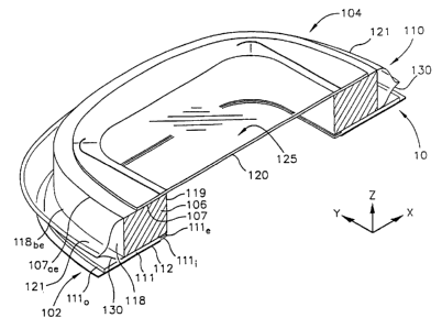
Fig. 15 is a perspective view of the preferred embodiment of a flexible non-
contact wound treatment device that embodies our invention;
Fig. 16 is a perspective view of a detachable heater in combination with our
1 ~ preferred embodiment;
Fig. 17 is an exploded view of our preferred embodiment;
Fig. 18A is a cross-sectional perspective view of our preferred embodiment
of the present invention;
Fig. 18B is the cross-sectional perspective view of our preferred embodiment
showing the operation of a membrane in adapting the wound treatment device to
body motion;
Fig. 18C is a magnified partial cross-sectional view of our preferred
embodiment showing further operation of the membrane in accommodating body
mot>on;
Fig. 19A is a side elevational view of the cross-sectional view of Fig. 18B
when attached to a human patient; and
Fig. 19B is a side elevational view representing the cross-sectional view of
Fig. 18C.
P:~AUGUSTIP1~153903.AM1 ~.~:a~~,.WJ J
- CA 02283997 1999-09-10
SUBSTITUTE PAGES PCTi'~ TS98/00345
.. ., "
SA
WOUND TREATMENT DEVICE OF WO 96115745
Further to the background of the invention of this application, reference is
made to FIGS. 1-14 in which embodiments and elements of a wound treatment
device
are illustrated. This device was the subject of WO 96/15745. With reference
especially to Fig. 1, a wound treatment device 10 has a planar upper surface
displaced
above the skin surface of the patient or person having a wound that is being
treated
by application and operation of the device 10. The wound treatment device 10
fiu-ther
includes an attachment surface generally held in a plane or surface that is
coincident
with the plane or surface of the person's skin. Together these two surfaces
define an
enclosed, non-contact volume over a wound treatment site.
The wound treatment device 10 that is illustrated in Fig. 1 may be considered
in a general way for the purpose of description. In this regard, the
description of a
wound treatment device is aided by considering three separate parts of the
wound
treatment device 10. These parts are an attachment portion 12, a wound
treatment
portion 14, and a transition portion 16. Each portion is designed to serve a
separate
function.
P:~AUGUSTTM153903.AM1 , ..
.. ~1 7~4
CA 02283997 1999-09-10
WO 98/46179 PCT/IJS98/00345
-6-
The attachment portion 12 is used to connect the wound treatment device 10 to
the
skin of a patient. The wouriil treatment portion 14 of the wound treatment
device 10
defines a vertical extent or dimension of the wound treatment device 10, and
thus defines
the location of the attachment surface. The transition portion 16 connects the
attachment
portion 12 to the wound treatment portion 14. The transition portion 16 is
provided to
improve the comfort and utility of the wound treatment device 10 when the
patient moves
and stretches the device.
Fig. 1 is a perspective view of a wound treatment device 10 applied to a
patient's
skin surface 18. A coordinate system 11 is depicted on the patient's skin
surface 18 and
it defines X, Y and Z directions. An attachment portion 12 is formed as an
planar rim or
flange. This attachment portion 12 is attached to the patient's skin 18 with
an adhesive and
it lies in a first XY plane. In this embodiment of wound treatment device 10,
a transition
portion 16 is integrally formed with attachment portion 12. Transition portion
16 rises
from the skin surface in the Z direction to connect to a wound treatment
portion 14. In this
embodiment, wound treatment portion 14 has a transparent planar wound cover 20
which
allows one to see a wound treatment area 28. Wound cover 20 is supported above
the first
XY plane by a foam ring standoff 15. Wound cover 20 lies in a second XY plane
that is
vertically displaced along the Z-axis by foam ring standoff 15 from the first
XY plane.
Wound cover 20 and foam ring standoff 15 together form wound treatment portion
14. The
region over wound treatment area 28 is called a wound treatment volume 24.
In this figure, wound treatment device 10 has been applied to a patient's skin
and
is in a relaxed state. In this unstressed state one can see an outer periphery
22 of
attachment portion 12. An inner periphery 23 is shown by a crease in the
structure where
it connects to transition portion 16.
Fig. 2 and Fig. 3 should be considered together where they show the influence
of
patient motion on wound treatment device 10. Both Fig. 2 and Fig. 3 are top
views of
wound treatment device 10 of Fig. 1 with the various portions of wound
treatment device
10 projected onto the first XY plane.
In Fig. 2, the wound covering is shown in a relaxed and un-stretched state
having
a nominal total projected area 27. Projected wound treatment area 28 is shown
at the center
of the wound treatment device 10. The outline of foam ring standoff 15 may be
seen as the
~,, ~, .
,..,, ~; .
v._. ,...~..,._. . . ~ ,
CA 02283997 2003-07-09
WO 98/46179 PCT/US98/00345
_7_
crosshatch area. bounded by an exterior perimeter 25 of foam ring standoff 15,
and an
interior perimeter 26 of foam ring standoff 1 S. A transition portion
projected area 17 is
bounded by inner periphery 23 of attachment portion 12, and interior perimeter
26 of foam
ring standoff 1'i. An attachment portion projected area 40 is shown as that
cross hatched
area bounded by outer periphery 22 and inner periphery 23 of attachment
portion 12.
Fig. 3 shows wound treatment device 10 stretched along the X-axis by patient
motion. In comparison to Fig. 2, the overall or total projected area 27 of
wound treatment
device 10 has increased. Attachment portion projected area 40 has increased
slightly as
attachment portion 12 moves with the underlying skin. Projected wound
enclosure area 28
is essentially unchanged in a~°ea since in this embodiment foam ring
standoff I S is free
move against the skin. The largest percentage area change occurs in transition
portion
projected area I7. As wound treatment device 10 deforms in response to patient
motion,
transition portion 16 is compliant and pays out material permitting the
majority of the
increase in fatal projected area 27 to be accommodated primarily by transition
portion
I S projected area 17.
Fig. 4 :shows a detachable heater 32 positioned for insertion into a pocket
formed
by pocket cover 2I , Pocket saver 2I is bonded to wound cover 20 and is sized
to retain
heater 32. Foam ring standoff 15 and wound cover 20 serve to stabilize the
shape of wound
treatment device 10 while transition portion 16 accommodates patient motion.
Consequently, heater 32 is reliably and comfbrtably positioned above the wound
surface.
In general, it us desirable to use a planar heater as heater 32 which has a
prescribed heat
output per unit area. This form of heater results in a more uniform flux of
radiant energy
applied to the wound. 'Ihe amount of heat supplied to the wound area is
largely
independent of the height of heater 32 above the wound surface within the
range of
functional heights of this device. In some cases, non-uniform wound area
heating might
be desirable and therefore the watt density of the heater may be non-uniform
across its
surface.
Fig. 5 is an exploded view of the first embodiment of wound treatment device
10.
Attachment portian 12 and transition portion membrane 36 are formed as a
unitary
composite shell 38. Composite shell 38 may be vacuum formed from closed cell
polyolefin
foams such as Volar~~~AS, which is a polyethylene material as sold by Illbruek
Ins., of
CA 02283997 1999-09-10
WO 98146179 PCT/US98/00345
_g_
Minneapolis, Minnesota. It should be apparent that many other materials may be
substituted within the scope of the invention. Foam ring standoff 15 may be
die cut from
foam sheeting of a reticulated polyurethane foam. The absorbency of the foam
as well as
its mechanical properties can be tailored to the particular wound treatment
application. For
example, the foam standoff may be impregnated with a medicament such as an
antibiotic,
antifungal, or antimicrobial material. It may also be desirable to supply a
deodorant
material or nitric oxide releasing material from the foam standoff. Wound
cover 20 and
wound pocket 21 may be made from a thin film of polyethylene. In general, the
composite
shell should be sufficiently self supporting so that when wound treatment
device 10 is
removed from its release liner, wound treatment portion 14 is held up or
supported by the
shaped flexion joint of transition portion membrane 36, and some effort is
required to evert
composite shell 38 and turn it inside out. This behavior defines the self
supporting feature
which causes foam ring standoff 15 to lie gently against the skin even when
wound
treatment device 10 is upside down. For larger wound coverings it may be
desirable to
apply a tacky adhesive to the patient contact surface of the standoff.
Fig. 6 is an exploded view of another embodiment of wound treatment device 10.
Attachment portion 12 and transition portion membrane 36 are formed as a
unitary
composite shell 38. In this embodiment, the wound treatment volume is defined
by a
serrated cup standoff 34. Standoff 34 may be made from a more rigid polymeric
material,
such as polyethylene, or the like. The serrations typified by a plurality of
serrations 44
permit serrated cup standoff 34 to flex and accommodate patient motion. This
embodiment
shows a release liner 42 coupled to attachment portion 12 of composite shell
38 with an
adhesive 46. In this embodiment, pocket cover 21 is bonded to composite shell
38.
Fig. 7 depicts a portable power supply 48 to provide for the ambulatory use of
the
heated versions of the wound treatment device. A collection of battery cells
may be wired
together to form power supply 48 which may be conveniently attached to a belt
49. A
suitable cable SO may be used to conduct power to heater 32. In many
instances, it may be
desirable to cut off power to heater 32 if wound treatment device 10 is
collapsed against
the wound so as to prevent overheating of the wound surface.
Fig. 8 shows a schematic representation of a touch switch 52 which may be
incorporated directly into detachable heater 32. Heater 32 includes a
continuous resistive
..
CA 02283997 1999-09-10
WO 98/46179 PCT/US98/00345
-9-
heating coil 51. A conductive membrane makes up touch switch 52 and is
arranged near
heating coil 51 so that it may "short out" segments or portions of coil 51 it
touches. In use,
all power to heating coil 51 is completely turned off by pressure applied to
an entire touch
sensor 53.
Fig. 9A shows an exploded version of heater 32 incorporating a touch switch 52
of
the type described schematically in Fig. 8. A switch cover 45 has a conductive
membrane
which is located over the conductive pattern of heating coil 51. It is held in
position with
an adhesive band 54. Fig. 9B shows the underside of switch cover 45 showing a
plurality
of discrete insulation bumps typified by a bump 47 which serve to space and
support touch
switch 52 above heating coil pattern 51. Pressure supplied to switch cover 45
inactivates
heater coil 51.
Fig. 10 shows an accessory device 55 or cover. This may take the form of a
passive
heater (or insulator) with a reflective surface facing the wound. Accessory
device 5 S may
also take the form of a mapping grid where a grid work of lines is positioned
on a
transparent card to permit tracking of the wound healing process.
Fig. l l A through Fig. l l D should be considered together. These drawings
facilitate
a description of the connection of the various structures of the invention and
represent
several alternative connection geometries. In general, to accommodate patient
motion, the
transition portion pays out stored material to increase the projected area of
the transition
portion. Each of these drawings represents a mechanical schematic cross
section of a
wound treatment device 10 in the XZ plane. In each Figure, the wound covering
is in the
relaxed state.
Fig. 11 A shows a schematic view of a ring standoff 15 extending from a first
plane
56 to a second plane 58. Transition portion 16 has a transition portion
membrane 60 which
is coupled to attachment portion 12 by a first flexible connection 62 formed
at the
intersection of attachment portion 12 and transition portion 16. Transition
portion
membrane 60 is connected to treatment portion 14 at a second flexible
connection 64 which
is formed at the intersection of transition portion 16 and wound treatment
portion 14.
Wound treatment portion 14 is generally a cylindrical cup-shaped structure
defining a
wound treatment area on the patient skin surface. A minimum interconnection
distance 66
is depicted as a dashed line extending from first flexible connection 62 to
second flexible
CA 02283997 1999-09-10
WO 98/46179 PCT/US98/00345
-10-
connection 64. The length of minimum interconnection distance 66 can be used
to
characterize the "length" of transition portion membrane 60. For many
embodiments of
the invention, the length of transition portion 16 between first flexible
connection 62 and
second flexible connection 64 is greater than the length of the straight line
drawn between
these points. This relationship is true for many embodiments of the wound
treatment
device when they are in the relaxed or unstressed position. It should be noted
that the
vertical distance between first plane 56 and second plane 58 represents a
minimum value
for minimum interconnection distance 66. In the XY plane, first flexible
connection 62
forms a first perimeter 61 and a second perimeter 63. In the embodiment
depicted in Fig.
11 A, first perimeter 61 is larger than second perimeter 63.
Fig. 11B is a mechanical schematic diagram which represents a cross section of
another embodiment of the wound treatment device IO with an alternate
connection
geometry. In this drawing, wound cover 20 extends radially beyond wound
treatment
volume 24 so that a second perimeter 68 is greater than a first perimeter 71.
This generates
a reflex transition portion 74 construction which may be adopted to increase
the "length"
and amount of material in the reflex transition portion 74.
Fig. 11 C shows a construction where a first perimeter 76 and a second
perimeter
78 have approximately the same value and are both concentric with an axis 90.
This
construction can produce an undulated transition portion 77. Once again, the
length of
undulated transition portion 77 exceeds the length of a line 65 between first
perimeter 76
and second perimeter 78.
Fig. 11 D shows a hemispheric shell 70 as wound treatment portion 14. In this
embodiment a second perimeter 80 is a single line of attachment that is
generally
concentric with axis 90. In this embodiment, a first perimeter 81 has a length
which greatly
exceeds the length of second perimeter 80. This construction forms a
hemispheric
transition portion 79 which has a length which exceeds the linear distance
between second
perimeter 80 and first perimeter 81 along a line 85.
Although the various geometries vary in detail, it is preferable to form
transition
portion 16 from a resilient material which is generally self supporting, yet
sufficiently
flexible so that it acts as a compliant hinge mechanism. This flexibility
substantially limits
the transfer of shearing force from wound treatment portion 14 to attachment
portion 12
_.. ~._~.,w......~.~. _., r . .
CA 02283997 2003-07-09
WO 98/46179 PtT/US98I00345
-I1-
of the wound treatment device I0, and visa versa. With the geometries set
forth in Fig.
11 A through Fig. 1 I D, transition portion 16 of wound treatment device 10
fornis a shaped
flexion joint or formed expansion joint which stores "material" in a pleat,
convolution,
bellows, or the like. This type of structure provides a means for expanding
the size of
transition portion 16 resulting in minimizing the transfer of forces from
attachment portion
12 to wound trE:atment portion I4.
Fig. 12A through Fig. 14B should be considered together. In these embodiments
of the invention, the standoff structure reduces in height resulting in
increased transition
portion projected area 17 during the stretching of the wound treatment device.
Fig. 12 A shows a part of a wound treatment device having foam ring standoff
15
in the unstressc;d or relaxed state. In this instance, transition portion
projected area 17 is
proportional to a dimension 88. In Fig. 12B, the wound treatment device has
been
stretched and the height of foam ring standoff 15 is reduced in the Z
direction which has
increased transition portion projected area 17 as represented by dimension 91.
Fig. 13 A shows a part of a wound treatment device having serrated cup
standoff 34
in the unstressed or relaxed state. In this instance, transition portion
projected area 17 is
proportional t~~ a dimension 98. In Fig. I3B, the wound treatment device has
been
stretched, and the height of serrated cup standoff 34 is reduced in the Z
direction. The
serrated wall sections splay out to permit the height reduction which
increases transition
portion projected area 17 as represented by a dimension 99.
Fig. 14A shows a part of a wound treatment device having foam ring standoff 15
in the unstressed or relaxed state. However, in this construction attachment
portion 12 and
a transition portion membrane 96 lie entirely in first plane 56. In this
instance, transition
portion projected area 17 is proportional to a dimension 94. In Fig. 14B, the
wound
treatment device has been stretched and the height of the foam ring standoff'
15 is reduced
in the Z direction. This height reduction increases transition portion
projected area 17
represented b:y a dimension 9 2.
Detailed Description of tree Invention
Our flexible, non-contact wound treatment device is illustrated in FIGS. 1 S-
19B
where the carne reference numerals specify identical parts throughout the
drawings.
CA 02283997 1999-09-10
WO 98/46179 PCT/US98100345
-12-
Fig.15 is a perspective view of a flexible, non-contact wound treatment device
I 00
for application to a patient's skin surface. An attachment portion 102 is
formed as a collar
or flange. This attachment portion 102 is for attachment around a wound
through an
adhesive layer on the underside of the attachment portion. Our preferred
embodiment of
wound treatment device I00 also embraces a wound treatment portion 104 that
includes a
wound cover 105, described below, supported by a support member in the form of
a
standoff 106. A transition portion 108 connects the wound treatment portion
104 to the
attachment portion 102 and preferably includes a membrane 110 that extends
around an
outer periphery of the support member I06 and is attached to the attachment
portion 102
between inner and outer peripheries thereof.
Referring now to Figs. 15 and 17, in the wound treatment device 100, the
attachment portion 102 is an integrated, unitary assembly preferably having
three sections:
a foam layer 111, an adhesive film layer 112 on a bottom surface of the foam
layer 111,
and a release liner 113 covering the adhesive film layer I12. One or more
lines of
weakness or perforation 114 are provided on the release liner 113 so that its
parts may be
separated and selectably peeled off of the adhesive film layer 112, thereby to
expose the
adhesive film layer 112 a section at a time for application to a person's
skin. The foam
layer 11 I may comprise a naturally open-celled polyurethane foam. The foam
layer 111
is preferably approximately 1/8" thick. The adhesive film layer 112 may
comprise a high
MVTR thin film, pressure sensitive adhesive (PSA) laminate available as a
package under
the trade name Mediderm from Bertek. The foam layer 111 is heat bonded to the
adhesive
film layer 112. The material of which the adhesive film layer I 12 is
comprised is selected
for a combination of adhesion level, permeability, and conformability
(stretching and
flexing with the skin} to allow prolonged skin contact, without complications.
The release
liner 113 is a white release paper coated with a release agent that is
provided on the
Mediderm 3701 product. The perforations or slits 114 are made during assembly
to aid in
the removal of the release liner 113 prior to attachment of a wound treatment
device to a
person.
When 111, 112 and 113 are assembled, the attachment portion 102 is a flexible
collar shaped part with an inner periphery portion 111 l on an upper surface
111 s of the
foam layer 111 around an inner perimeter, or edge, 111 e. The upper surface
111 s faces,
. _ ..~~ _ ... r . . _.. .. .
CA 02283997 1999-09-10
WO 98/46179 PCT/US98/00345
-13-
and is therefore disposed under, or beneath, the support member 106. The
attachment
portion I02 further includes an outer perimeter, or edge, 1110.
The wound treatment portion 104 includes the support member 106, which is
preferably a ring of absorbent foam such as a naturally open-celled
polyurethane foam that
is selected to have favorable characteristics of absorbency, leaking and
resevoiring. Such
material is available as a product sold under the trade name Aquazone from
Foamex. The
support member 106 has an upper surface 107, a lower surface (109 in Figs. 18B-
198), an
outer perimeter, or edge, 1 I 8 and an inner perimeter, or edge, 119. The
thickness of the
support member I06 is preferably in a range extending from I/2" to 5/8", with
the exact
dimension being selected to maintain non-contact at wound sites whereby,
during use, the
foam ring can compress and conform without the wound cover contacting the
wound. The
wound cover 1 OS in the preferred embodiment includes a layer 120 preferably
of 4 mil.-
thick clear, flexible polyurethane film with favorable characteristics
selected, but not
limited, to include moisture vapor transfer, oxygen permeability, and
transmission of
infrared radiation. Such material is available as a product sold under the
trade name
Deerfield 61005. The layer 120 is attached to the upper surface 107 of the
support member
106 by a ring 124 of adhesive comprising a synthetic rubber-base adhesive such
the product
sold under the trade name HL-2306-X by H.B. Fuller Adhesive. When the layer
120 is
attached to the upper surface 107 of the support member 106, a perimeter
portion 121 of
the layer 120 extends out beyond the outer perimeter 118 of the support member
106. The
wound cover 1 OS further includes a stretcher layer 125 attached to the Iayer
120 so that the
layer 120 is sandwiched between the stretcher layer 125 and the upper surface
I 07 of the
support member 106. The stretcher layer I25 is a 5 mil-thick planar sheet of
(preferably)
clear, somewhat flexible polyester film having enough stiffness to aid in
maintaining
planarity of the wound treatment portion 104. The function of the stretcher
layer 125 is to
hold the layer 120 taut, much as a "stretcher frame" tautens an artist's
canvas. The stretcher
layer 125 is attached to the layer 120 by a layer 126 of adhesive comprising a
clear flexible
polyester carrier film coated on both sides with an aggressive adhesive. The
adhesive layer
126 is oriented over the support member 106. A film carrier allows for the
adhesive to be
run in a web process and die cut during manufacturing of the stretcher layer
I25. The
stretcher layer 125 further includes a pair of slits 128 that receive a
detachable heater. With
CA 02283997 1999-09-10
WO 98/4b179 PCT/US98/00345
-14-
the provision of the slits 128, a pocket is formed between the stretcher layer
125 and the
layer 120.
The transition portion 108 includes a lower collar 130 that is preferably
formed
from the same material as the layer I 20. The transition portion 108 also
includes the outer
perimeter portion 121 of the layer 120 that extends out beyond the support
member 106
when assembled thereto. When the wound treatment device 100 is assembled, a
circumferential edge 122 of the layer 120 is joined to a corresponding
circumferential edge
132 of the lower collar 130. Preferably, the edges 122 and 132 are sealed or
welded
together by a heat process. When so joined, the outer perimeter portion 121 of
the layer
120 and the lower collar 130 form the membrane 110, which extends over the
outside of
the outer perimeter 1 I 8 of the support member 106. The lower collar has a
ring-like shape
that includes an inner periphery 131. An inner periphery portion 133 comprises
an annular
portion of the lower collar material on a surface of the lower collar that
faces away from
the lower surface 109 of the support member 106. The lower surface 109 is not
shown in
Fig. 17, but may be seen in Figs. 19A and 19B.
The membrane 110 of the transition portion 108 is attached to the attachment
portion 102 by heat-bonding or otherwise connecting the inner periphery
portion 133 of the
lower collar 130 at or near the opposing inner periphery portion I 11 i of the
attachment
portion 102.
Many variations of the assembly illustrated in Figs. 15 and 17 are possible.
For
example, the support member 106 could be contained within the structure formed
by the
layer 120, lower collar 130, and attachment portion 102, unattached to any
portion of the
structure.
Fig. 16 shows a detachable heater 140 positioned on the wound cover 105 within
a pocket formed between the layer 120 and the stretcher layer I 25, with the
opening to the
pocket provided by one of the slits 128. The wound cover 105, with the heater
140
contained within the pocket, is supported substantially in a plane or surface
above a wound
by the support member 106. The heater 140 is generally planar and may be
connected to
and powered by a portable power supply such as that illustrated in Fig. 7.
Refer now to Figs. 18A-18C in which Figs. 18A and 18B show details of the
wound
treatment device 100 when assembled and put in use. Fig. 18A illustrates the
relationship
____ w... ._ T , .
CA 02283997 2003-07-09
WO 98//6179 PCI'NS9SI003~5
-15-
of the attachment portion 102 with respect to the support member 106 of the
wound
treatment porf:ion ID4. In this regard, when the wound treatment device is
assembled and
placed on a flat surface, the attachment portion 102 and wound treatment
portion 104
substantially malign along the inner perimeters 119 and 111 e.
The sc;al between the inner periphery portion 133 of the lower collar 130 and
the
inner periphery portion 111 l of the attachment portion 102 lies beneath the
lower surface
of the support: member 106. This is the surface that is indicated by reference
numeral 109
in Figs. 19A and 19B. Preferably, the seal joining the inner periphery
portions 133 and
111 l is a continuous, closed-~Ioop seal. Although, for reasons explained
below, this is the
preferred location of the seal between the lower collar 130 and attachment
portion 102, the
inventors contemplate than the sea! could comprise a substantially continuous,
closed-loop
trace anywhrrc between the outer perimeter 111 o and inner perimeter 111 a of
the
attachment member 102.
In Figs. 17 and 18A, the seal bctwxn the edges 122 and 132 of the layer 120
and
lower collar 130 is exaggerated as a flange. In practice, the shape of the
membrane 110
extending from an upper outer edge 107ae of the upper surface 107 to a lower
outer edge
118be of the outer perimeter 118 is rather elongated, with the flange much
less pronounced
than shown in Fig. 18A. Of course, the membrane 110 in the extent: from the
edge 107ue
all the way down to the seal that joins the inner periphery portions 133 and l
l 1i is not
attached, and, is therefore fm from, although in close proximity to, the outer
perimeter 118,
lower edge 118be and lower surface 109 of the support member 1 OG.
Rafexring now to Figs.18B-19B, the flexible, non-contact wound treatment
device
100 ofthis iiavention is suitable for placement onto a skin surface 150 of a
patient or person
so as to inchxde a selected wound area 152 that abuts a treatment volume 156
within the
wound tr~nent device 100. This attachment may be directly to the skin surface
1 S0, or
on another member such as an ostomy ring that is, in turn, mounted or attached
to the skin
surface 150. As Figs. 18B-19B demonstrate, the flexible, non-contact wound
treatment
device 100 ofthis invention satisfies the objective previously stated by a
capability of being
conformably attached to an uneven, changing surface supporting a wound
treatment portion
104 that remains reasonablvy or substantially planar in itR shape, regardless
of body contour
or movements. In this regard, as Figs. 18B and 19B illustrate, the attachment
portion 102
CA 02283997 1999-09-10
WO 98/46179 PCT/US98100345
-16-
operates as a hinge or flexion joint that pivots at the seal between the inner
periphery
portions 133 and 111 l. Relatedly, the attachment portion 102 is free to
conform to the
shape of the skin surface by flexibly deforming between the inner and outer
perimeters
111 a and 1110. At the same time, the wound treatment portion 104 is
relatively
undeformed so that the support member 106 is able to support the layer I20 and
stretcher
layer 125 in a relatively planar orientation with respect to the wound area
152. In the
meantime, the wound treatment device 100 forms a barrier between the wound
treatment
volume 1 S 6 and the ambient atmosphere by virtue of the seal between the
edges 122 and
132 of the layer 120 and lower collar 130, and the seal between the inner
periphery portions
133 and 11 I l. The bottom of the wound treatment device 100 is sealed to the
skin 150
when the release layer 113 is peeled off so that the adhesive film layer 112
seals to the skin
surface 15 0.
Figs. 18C and 19B illustrate the conformability of the wound treatment device
100
provided by flexion of the membrane 110 in the transition portion 108. Figs.
18C and 19B
are "snap shots" of the flexible, non-contact wound treatment device 100 after
placement
as described above with reference to Figs. 18B and 19A and after movement of a
body part
on which the device I 00 is placed. In these figures, movement is accommodated
by excess
length in the membrane 110. In Figs. 18C and 19B, the membrane 110 has
tensioned along
the perimeter 118 to provide strain relief between the lower edge 1 l8be of
the support
member 106 and the seal between the inner periphery portions 133 and 11 l l.
In addition,
the flexibility of the membrane 110 and its freedom from the outer perimeter
118 and lower
surface 109 permit a play out of excess length of the membrane 110 that abuts
the outer
perimeter 118 of the support member 106. This moves the membrane 110 into
close
touching engagement with the outer perimeter 118, while lengthening the amount
of
membrane I 10 available between the lower edge 118be and the inner periphery
portion
llli.
In another aspect, as Figs. 18C and 19B show, the membrane I 10 acts as a
double
hinge or a double pleat between the lower edge 118be of the support member 106
and the
attachment portion 102. A first hinge pivot or pleat is at the seal between
133 and l l Ii.
This hinge permits the attachment portion to pivot toward and away from the
wound
treatment portion. The second hinge - at edge 118be - allows the wound
treatment portion
w.....,...~... ~
CA 02283997 1999-09-10
WO 98146179 PCT/US98/00345
-17-
to move toward and away from the attachment portion. Manifestly, the same
effect could
be achieved by attachment of the membrane 110 to the lower surface 109 inside
of the edge
118be.
Three significant advantages result from placement of the attachment portion
102
beneath the support member 106 of the wound treatment portion.
First, in plan, the shapes and extents of the bottom surface 109 and the
attachment
portion 102 align and largely overlap, thereby reducing the "foot print" of
the wound
treatment device 100 to a single, substantially annular shape from the two
concentric
shapes of Figs. 2 and 3.
Next, the double hinge (or pleat) provided by the membrane 110 increases the
conformability of the wound treatment device to shape and movement, while
maintaining
the planarity of the wound cover and preventing its contact with a wound.
Last, the lower collar 130, in extending substantially to the inner perimeter
111 a of
the attachment portion 102 forms a barrier to moisture and wound exudate which
may be
absorbed by the support member 106, thereby reducing maceration of skin
underneath the
attachment portion 102.
While the invention has been illustrated by means of specific embodiments and
examples of use, it will be evident to those skilled in the art that many
variations and
modifications may be made therein without deviating from the scope and spirit
of the
invention. However, it is to be understood that the scope of the present
invention is to be
limited only by the appended claims.