Note: Descriptions are shown in the official language in which they were submitted.
CA 02284333 1999-09-29
Robert E. Myer 63
NESTED FEED FORWARD DISTORTION REDUCTION SYSTEM
BACKGROUND OF TAE INVENTION
1. Field of The Invention
This invention relates to amplifiers and, more particularly, to a nested feed
forward distortion reduction system for amplifiers.
2. Description of Related Art
Amplifiers Qften add undesired distortion to a signal, creating an output
signal
1o comprising distortion or nonlinear components and the input signal
component. The
distortion includes any undesired signals added to or affecting adversely the
signal.
There is therefore a need to devise techniques that can eliminate
substantially or
reduce significantly the distortion produced by the amplifier.
Feed-forward correction is routinely deployed in modern amplifiers to
15 improve amplifier linearity with various input patterns. The essence of the
feed-
forward correction is to manipulate distortion, such as intermodulation (IMD)
components, created by the amplifier so that at the final summing point, the
distortion
cancels out. Due to the unpredictability of the input signal pattern as well
as the
resultant distortion location, some feed forward schemes inject a known
signal, i.e. a
2o pilot signal, in the main signal path to go with the distortion produced by
the
amplification process. By designing the feed forward distortion reduction
circuitry to
detect and reduce the pilot signal, the distortion is also reduced.
FIG. 1 discloses a feed forward correction circuitry 10 which can use a pilot
signal to reduce distortion produced by RF amplifier 12. A signal, such as a
carrier
25 ~ signal, is applied to a splitter 14. The splitter 14 replicates or
produces an analog
representation of the signal on a main signal path 16 and a feed forward path
18. The
splitter 14 is part of a feed forward loop referred to as loop # 1, which in
addition to
the splitter 14, comprises a gain & phase circuit 20, coupler 22, the RF
amplifier 12,
delay circuit 24 and couplers 26 and 28. The signal on the main path 16 is
applied to
3o gain & phase circuit 20. The output of gain & phase circuit 20 and the
pilot signal
are applied to the coupler 22. Typically, the amplitude of the pilot signal is
much less
CA 02284333 1999-09-29
Robert E. Myer 63 2
(e.g., 30 dB less) than the amplitude of the signal so as not to interfere
with the
operation of the amplifier 12. The output of the coupler 22 is applied to the
amplifier
12 whose output comprises the amplified signal, the amplified pilot signal and
distortion signals produced by the amplifier 12. A portion of the output of
the
amplifier 12 is obtained from the coupler 26 and is combined with a delayed
version
of the signal (signal on path 18) at the coupler 28 via coupling path 30. The
signal on
the path 18 has experienced sufficient delay provided by delay circuit 24 so
that such
signal experiences the same delay as the signal appearing at the coupler 28
via the
path 30.
to The gain & phase circuit 20 is controlled via control path 32 with control
signals to adjust the gain and phase of the signal such that the signal
appearing at the
coupler 28 via the path 30 is substantially the inverse (equal in amplitude
but 180°out
of phase) of the delayed signal at the coupler 28. The control signal
appearing on the
control path 32 of the gain & phase circuit 20 is derived from the signal at
point A in
15 a well known manner such as the use of detection circuits. The detection
circuits
detect well known electrical signal characteristics such as amplitude, phase,
and
frequency of the signal. Therefore, the signals applied to the coupler 28
substantially
cancel each other leaving at point A the pilot signal and the distortion
produced by
the amplifier 12. Loop # 1 is thus a feed forward loop which serves to isolate
at point
2o A the pilot signal and distortion signals produced by the amplifier 12.
The signals appearing at point A (pilot signal and distortion signals) are fed
to
gain & phase circuit 34 whose output is fed to main correction amplifier 36
whose
output is applied to coupler 38. A portion of the output signals (signal,
pilot signal
and distortion signals) of the amplifier 12 is fed to delay circuit 40 whose
output is
25 fed to the coupler 38. The delay circuit 40 is designed such that signals
from the
output of the amplifier 12 applied to the coupler 38 experience substantially
the same
delay as the signals from the output of the amplifier 36 applied to the
coupler 38.
The pilot signal is used to obtain information about how well the distortion
is
being cancelled from the main signal pathl6. The information is obtained by
3o detecting well known electrical signal characteristics of the pilot signal,
such as the
CA 02284333 1999-09-29
Robert E. Myer 63 3
amplitude; spectral content, phase response of the pilot signal. For example,
the
amplitude of the pilot signal after cancellation at the coupler 38 can
indicate how well
the distortion is being cancelled. If the amplitude of the pilot signal is
small after the
coupler 38, the amplitude of the distortion is also small. Detection circuit
42, such as
a mixer connected to a log detector (or other known detection circuits), will
detect the
pilot signal and use this information to generate control signals onto path 46
to cause
the gain & phase circuit 34 to modify the pilot signal at point A such that
the pilot
signal on the main path 16 at the coupler 38 is substantially the inverse
(equal in
amplitude but 180° out of phase) of the pilot signal on the feed
forward path 18 at the
1 o coupler 38. The corresponding pilot signals and the distortion signals at
the coupler
38 substantially cancel each other respectively at the coupler 38 leaving the
signal (or
an amplified version of the signal) at the output of the system. Therefore,
loop # 2,
which comprises the coupler 26, the coupler 28, the gain & phase circuit 34,
the
amplifier 36, the coupler 38 and the delay circuit 40 is a feed forward loop
which uses
~ 5 the information obtained from the pilot signal to cancel substantially the
distortion
produced by the amplifier 12.
In actual systems, however, there is rarely an absolute cancellation of the
distortion and the pilot signals. Feed forward distortion reduction systems
require
tight operating tolerances, for example, to achieve a 30dB reduction in IMDs,
typical
2o feed forward correction systems may require a + or - .1 dB frequency flat
response
(amplitude deviation over the frequency band of operation) and a + or - 1
degree
phase linearity (phase deviation from a straight line in the frequency band of
operation). To obtain this accuracy is difficult. In feed forward distortion
reduction
signals which use a pilot signal, the amplitude of the pilot signal is
typically relatively
25 small at the output of the feed forward distortion reduction system because
of the
cancellation of the pilot and the relative amplitude of the pilot signal with
respect to
the amplitude of the output signal. Thus, it becomes difficult to detect the
pilot signal
at the output of the system. To improve detection of the pilot signal at the
output of
the distortion reduction system, schemes are developed to generate the pilot
signal at
CA 02284333 1999-09-29
Robert E. Myer 63 4
an appropriate location and to improve detection and control. Such schemes
typically
add costs to the systems.
PilotIess feed forward distortion reduction schemes have been developed to
eliminate the pilot signal, thereby eliminating the need for the pilot
generation,
detection and control circuitry, such as the coupler 22 and pilot detection
circuit 42.
The pilotless feed forward reduction systems, however, do not have a known
pilot
signal which can be detected at the output of the feed forward distortion
reduction
system to compensate for changing operating conditions. Instead of detecting
the
pilot signal to improve cancellation at the coupler 38, the pilotless feed
forward
1o systems can use gain and phase control circuitry 54 responsive to the
inputs from the
couplers 56 and 58 to produce gain and phase control signals to the gain and
phase
circuits 34. In response, the gain and phase circuits 34 provide variable
phase and/or
gain adjustments which maintain the appropriate gain and/or phase for the
distortion
on the feed forward path 18 to improve reduction of the distortion of the main
signal
t5 path 16 at the coupler 38. The gain and phase control circuitry adds costs
and
complexity, and to achieve adequate reduction of the distortion is difficult.
For
example, the correction amplifier 36 produces the amplified distortion with
second
distortion which is injected into the main signal path 16.
A need exists for a distortion reduction system that can provide adequate
2o distortion reduction while reducing any problems associated with other
distortion
reduction systems.
SUMMARY OF TAE INVENTION
The present invention involves a.nested feed forward distortion reduction
25 ' system which in reducing the distortion from a main amplifier on a main
signal path
uses a nested feed forward arrangement for the correction amplifier to reduce
the
distortion produced from the correction amplifier. In reducing the distortion
from the
correction amplifier(s)and using progressively higher quality correction
amplifier(s),
the nested feed forward arrangement produces an improved, more stable
3o representation of the distortion from the main amplifier, thereby
alleviating the need
CA 02284333 1999-09-29
Robert E. Myer 63 5
for variable gain and/or phase control in producing amplified signal with
reduced
distortion:
For example, a feed forward distortion reduction system receives a signal to
be amplified on a main signal path and produces an analog representation of
the
signal onto the main signal path and a feed forward path. The signal on the
main
signal path is applied to the main amplifier whose output comprises the
amplified
signal and distortion signals produced by the main amplifier. A portion of the
output
of the main amplifier is placed on a coupling path and combined with a delayed
version of the signal on the feed forward path to isolate the distortion
produced from
1 o the main amplifier onto the feed forward path. The distortion on the feed
forward
path is fed to a nested feed forward arrangement. The nested feed forward
arrangement provides the distortion to a main correction amplifier which
amplifies
the distortion from the main amplifier and generates second distortion. The
nested
feed forward arrangement reduces the second distortion from the correction
amplifier
~ 5 using a smaller, higher quality second correction amplifier to produce an
improved
and more stable representation of the distortion from the main amplifier. By
using an
improved, more stable representation of the distortion from the main amplifier
to
reduce the distortion on the main signal path, the nested feed forward
distortion
reduction system provides improved distortion reduction and alleviates the
need for
2o phase and/or gain control. Using successive nested feed forward
arrangements
provides increasingly stable and more accurate representations of the
distortion from
the main amplifier.
In a exemplary nested feed forward arrangement, the distortion on the feed
forward path is split onto a main correction path and a nested feed forward
path. The
25 ~ distortion signal on the main correction path is fed to the main
correction amplifier
which produces an amplified distortion signal with second distortion produced
from
the main correction amplifier. A portion of the output of the main correction
amplifier is placed on a coupling path and combined with a delayed version of
the
distortion on the second feed forward path to isolate the second distortion
produced
3o from the main correction amplifier onto the second feed forward path. The
second
CA 02284333 1999-09-29
Robert E. Myer 63 6
distortion on the second feed forward path is fed forward through a second
correction
amplifier to reduce the second distortion from the main correction amplifier
on the
main correction path. The amplified distortion signal with reduced second
distortion
is used to provide improved reduction of the distortion from the main
amplifier on the
main signal path. The quality of the second correction amplifier controls the
amount
of distortion reduction in the feed forward distortion reduction system with
the nested
feed forward distortion reduction system.
Using this nested feed forward arrangement with a second correction amplifier
of higher quality than the main correction amplifier reduces the need to use
relative
1 o variable gain and/or phase control between the distortions on the second
correction
path and the nested feed forward path and/or between the signals on the main
signal
path and the feed forward path. Fixed gain and/or phase control can be used
because
the operation of the fixed feed forward distortion reduction system is
controlled by
the operation of the nested, higher quality correction amplifier. Since the
correction
15 amplifier handles smaller power levels, it can be of higher quality in that
the
correction amplifier produces a more linear representation of the input signal
and is
more temperature stable. As such, the nested feed forward arrangement produces
a
stable, less distorted representation of the distortion from the main
amplifier, and the
less distorted representation of the distortion can be used to reduce the
distortion on
2o the main signal path. Successive nested feed forward arrangements can be
used to
further improve the performance of the nested feed forward distortion
reduction
system and/or further reduce the need to use variable gain and/or phase
control. A
second nested feed forward arrangement for the second correction amplifier can
be
nested within the first nested feed forward arrangement. The second nested
feed
25 ' forward arrangement uses a third correction amplifier, which is yet
smaller and of
higher quality than the second correction amplifier, to reduce the second
distortion
from the second correction amplifier. As such, the third correction amplifier
controls
the distortion reduction performance of the distortion reduction system.
Because the
third correction amplifier is smaller, the overall efficiency of the system is
not
3o affected. Because the third correction amplifier is of higher quality and
more stable,
CA 02284333 1999-09-29
Robert E. Myer 63 7
the forward distortion reduction system can be fixed and not require the
variable gain
and/or phase control.
BRIEF DESCRIPTION OF THE DRAWINGS
Other aspects and advantages of the present invention may become apparent
upon reading the following detailed description and upon reference to the
drawings in
which:
FIG. 1 is a block diagram of a prior art feed forward distortion reduction
scheme used for RF amplifiers;
1 o FIG. 2 shows a general block diagram of a feed forward distortion
reduction
system using a nested feed forward arrangements) according to the principles
of the
present invention; and
FIG. 3 shows a particular embodiment of a feed forward distortion reduction
system using nested feed forward arrangements according to the principles of
the
15 present invention.
DETAILED DESCRIPTION
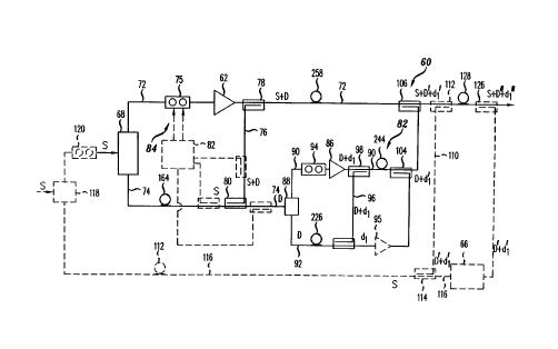
An illustrative embodiment of a nested feed forward distortion reduction
system according to the principles of the present invention is described
below. FIG. 2
2o shows a general block diagram of a nested feed forward distortion reduction
system
60 which is fixed and does not use variable phase and/or gain control to
reduce the
distortion from the output of an RF amplifier 62. The feed forward distortion
reduction system 60 is shown as a first stage in a multiple stage pilotless
feed forward
reduction system which includes a second feed forward reduction stage 66 in
dashed
2s lines as would be understood by one of ordinary skill in the art with the
benefit of this
disclosure. Although the nested feed forward distortion reduction system is
described
as fixed, varying the gain and phase of signals to improve cancellation can be
performed in the second stage 66, between the system 60 and stage 66, or in
system
60 in certain embodiments.
CA 02284333 1999-09-29
Robert E. Myer 63 8
The feed forward distortion reduction system 60 receives from a sputter 68 a
signal S to be amplified and produces an analog representation of the signal S
on a
main signal path 72 and-a feed forward path 74. The signal S on the main
signal path
72 is applied to a gain & phase circuit 75. The output of gain & phase circuit
75 is
applied to the amplifier 62 whose output comprises the amplified signal S with
distortion D produced by the amplifier 62. A portion of the output S and D of
the
amplifier 62 is placed on a coupling path 76 by a coupler 78 and combined at
the
coupler 80 with a delayed version of the signal S on the path 74 to isolate
the
distortion D produced from the amplifier 62.
1o In this embodiment, the gain & phase circuit 75 adjusts the amplitude and
phase of the signal on the main path 72 by a fixed amount. Other embodiments
can
control the phase and gain circuit with a phase and gain controller 82. The
control
signals) appearing on the control paths) 84 of the gain & phase circuit 75 is
derived
from the portion of the amplified signal S and D on the coupling path 76 and
the
15 delayed version of the signal S on the path 74 and/or from the output of
the coupler
80. The phase and gain circuit 75 adjusts the amplitude and phase of the
signal S on
the main signal path 72 prior to the amplifier 62 such that the amplified
signal S and
D at the coupler 80 is substantially the inverse (equal in amplitude but
180°out of
phase) of the delayed signal S on the path 74. As such, the combining signals
cancel
2o to isolate the distortion D. As the cancellation of the combining signals S
improves,
the feed forward distortion reduction improves the isolation of the distortion
D on the
second path 74 at the output of the coupler 80. The feed forward distortion
system 60
feeds forward the isolated distortion D on the path 74 through a nested feed
forward
arrangement 82 to reduce the distortion D on the main signal path 72 by
combining
25 ' the distortion D on the path 72 with a representation of the distortion D
from the
nested feed forward arrangement 82 which adds minimal distortion to the
representation of the distortion D.
In this embodiment, the output of the coupler 80 is applied to the nested feed
forward arrangement 82 for a main correction amplifier 86. The distortion D on
the
3o feed forward path 74 is split by a splitter 88 onto a correction path 90
and a second
CA 02284333 1999-09-29
Robert E. Myer 63 9
feed forward path 92. On the correction path 90, the distortion D is applied
to a gain
& phase adjuster 94 which adjusts the amplitude and phase of the signal D. The
phase and gain adjuster 94 can be fixed in this embodiment because the nested
feed
forward arrangement 82 uses a second correction arrangement 95 which results
in a
stable and linear representation of the signal D on the correction path 90.
Other
embodiments could provide control signals to adjust the gain and phase of the
phase
and gain circuit 94 as described above for the phase and gain circuit 75.
The output of gain and phase adjuster 94 is applied to the main correction
amplifier 86 whose output comprises the amplified signal D and distortion
signals dl
to produced by the main correction amplifier 86. A portion of the output D and
dl of
the correction amplifier 86 is placed on a nested coupling path 96 by a
coupler 98 and
combined at the coupler 100 with a delayed version of the signal D on the
second
feed forward path 92 to isolate the distortion dl produced from the main
correction
amplifier 86.
The feed forward arrangement 82 feeds forward the isolated distortion dl on
the second feed forward path 92 through the second correction amplifier
arrangement
95 to a coupler 104. The second correction amplifier arrangement 95 can simply
be a
second correction amplifier. Alternatively, the arrangement 95 can be a second
nested feed forward arrangement including a second correction amplifier and
third
2o correction amplifier to reduce any distortion produced from the second
correction
amplifier. Using the nested feed forward arrangement enables the use of
smaller,
more stable and/or more linear amplifiers as nested correction amplifiers
which
control the performance of the feed forward distortion reduction system 60. As
such,
fixed relative phase and/or gain adjustments can be made between combining
signals
2s because the operation of the system 60 by the more stable higher quality,
nested
correction amplifier. If the main amplifier and/or main correction amplifier
produces
more distortion due to changing operating conditions, such as changing
temperature,
signal strength or signal frequency, the nested feed forward arrangement will
enable
the successive reduction of the distortion by continuing to produce an
accurate
3o representation of the distortion.
CA 02284333 1999-09-29
Robert E. Myer 63 10
At the coupler 104, the second distortion dl on the second feed forward path
combines with a delayed version of the distortion D with dl on the correction
path 90
to reduce the distortion dl on the correction path 90. The arrangement 82 is
designed
such that corresponding portions of the signals dl applied to the coupler 104
destructively combine to produce at the output of the coupler 104 the
amplified
distortion D with reduced distortion dl'. The distortion D with reduced
distortion d1'
is fed forward to a coupler 106 where the distortion D with dl' combines with
a
delayed version of the signal S with distortion D to reduce the distortion
from the
main amplifier 62 on the main signal path 72. Because the distortion dl' from
the
1o correction amplifier 86 has been reduced, the reduction of the distortion D
from the
main signal path 72 is improved.
In certain embodiments, the nested feed forward distortion reduction system
60 can be used in a distortion reduction system having multiple feed forward
reduction stages to cumulatively reduce the distortion from the output of the
previous
stage(s). For example, the nested feed forward distortion reduction system 60
can act
as a first stage which produces the signal S with reduced distortion D' and
dl'. The
second feed forward reduction stage 66 receives as the input signal the
reduced
distortion D' and dl' from the nested feed forward reduction stage 64 via a
coupling
path 110. A coupler 112 couples a portion of the signal S with reduced
distortion D'
2o and dl' from the main signal path 72 onto the coupling path 110. A coupler
114
receives the signal S with distortion D' and dl' from the coupling path 110
and
combines the signal S and the distortion D' and dl' from the coupling path 110
with a
delayed signal S on a path 116 which was obtained from splitter 118. In this
embodiment, the splitter 118 receives the signal S and provides versions of
the signal
' S to a phase and gain adjuster 120 prior to the splitter 68 of the nested
feed forward
system 60 and the path 116. The signal S on the path 116 is delayed by a delay
122.
The signal S on the path 116 experiences sufficient delay provided by the
delay
circuit 122 such that signal S experiences the same delay as the signal S
appearing at
the coupler 114 via the path 110. The coupler 114 destructively combines the
signal
3o S from the second coupling path 102 and the signal S from the path 116 and
isolates
CA 02284333 1999-09-29
Robert E. Myer 63 11
the remaining distortion D' and d,' from the nested feed forward system 60 on
the
path 116 leading to the second feed forward stage 66.
In this embodiment, the gain & phase adjuster 120 is fixed but embodiments
could use a phase and gain controller to adjust the gain and phase provided by
the
gain and phase circuit 120 to the signal S prior to the amplifier 62 such that
the
amplified signal S, D' and dl' at the coupler 114 is substantially the inverse
(equal in
amplitude but 180°out of phase) of the delayed signal S on the path
116. In some
embodiments, the gain and phase control circuit provides control signals) to
the gain
& phase circuit 120~derived from the portion of the amplified signal S, D' and
dl' on
to the coupling path 110 and the delayed version of the signal S on the path
116.
Because the desired amplitude and phase relationship (for example, the
combining
signals have the same amplitude and are 180 degrees out of phase) is
maintained
between the combining signals, the combining signals S sufficiently cancel to
isolate
the distortion D' and dl' at the coupler 114. In other embodiments, the gain
and
phase control circuit can be a logarithmic detector and a nulling circuit. In
such an
embodiment, a coupler produces a sample of the signal after the output of the
coupler
114 to the log detector which produces a signal indicative of the amplitude of
the
signal. A nulling circuit attempts to reduce the signal from the log detector
to
improve cancellation of the signal and isolate the distortion D' and dl' after
the
2o coupler 114 by providing control signals to the phase and gain adjuster
120.
In this embodiment, the second feed forward arrangement 66 as well as any
additional feed forward stages (not shown) can be configured to operate as
described
above for the nested first feed forward system 60 or could simply be an
amplifier. As
such, the second feed forward stage 66 produces a version of the reduced
distortion
D' and dl'. The distortion D' and dl'(as well as any minor distortion signals
introduced by the amplifiers (not shown) in the second feed forward stage 66)
is fed
forward to fiuther reduce the distortion D' and dl' from the amplified signal
S at a
coupler 126, The coupler 126 combines the distortion signals D' and d~' from
the
second feed forward stage 66 with a delayed version of the signals S with
distortion
3o D' and dl' on the main signal path 72 to fiwther reduce the distortion D'
and dl'
CA 02284333 1999-09-29
Robert E. Myer 63 12
produced from the nested feed forward system 60. The signals S with distortion
D'
and d,' are fed to a delay circuit 128 which is designed such that signals
from the
outputs of the coupler 1 i2 applied to the coupler 126 experience
substantially the
same delay.
FIG. 3 shows a detailed implementation of a nested feed forward distortion
reduction system 140 using successive nested feed forward an~angements 142 and
144. A signal S to be amplified by main amplifier 146 is received by the
nested feed
forward system 140, and a splitter 148 replicates or produces analog
representations
of the signal S onto a main signal path 150 leading to the main amplifier 146
and onto
a feed forward path 152 leading to nested feed forward arrangements 142 and
144.
On the main path 150 in this embodiment, the signal is applied to a gain &
phase
adjuster 156 which adjusts the phase and gain of the signal S on the main path
72. In
this embodiment, the nested feed forward system does not require the phase and
gain
circuit to be controlled to provide a varying gain and phase. Instead, the
gain and
phase circuit 156 provides a fined gain and phase adjustment to the signal S
on the
main path 150.
The output of gain and phase adjuster 156 is applied to the amplifier 146
whose output comprises the amplified signal S and distortion signals D, such
as third
order IMDs produced by the amplifier 146. A portion of the output of the
amplifier
146 is obtained from a coupler 158 and placed on a coupling path 160. The
signal S
with D on the coupling path 160 is combined with a delayed version of the
signal S
on the feed forward path 152 at the coupler 162. The signal S on the path 152
has
experienced sufficient delay provided by a delay circuit 164 so that such
signal S
experiences the same delay as the signal.S appearing at the coupler 162 via
the path
2s ' 160. The gain & phase circuit 156 provides fixed gain and phase
adjustments which
adjust the amplitude and/or phase of the signal S on the main path 150 such
that the
signal S appearing at the coupler 162 via the path 160 is substantially the
inverse
(equal in amplitude but 180°out of phase) of the delayed signal S at
the coupler 162.
In general, a phase difference of 179 to 181 degrees and an amplitude
difference of +
or - .1 dB between the combining signals can achieve a cancellation of 30dB,
and a
CA 02284333 1999-09-29
Robert E. Myer 63 13
175-185 degree phase difference and a 2dB amplitude difference can provide
almost
20 dB of cancellation.
In this embodiment, a remaining signal S can appear at the output of the
coupler 162 (along with the distortion D), and an improved combination of the
remaining signal S (leakage signal S) and the signal S from the path 170 is
made at a
coupler 166. For example, after the coupler 162, some leakage signal S can
remain
on the path 152 after the coupler 162. As such, a coupler 168 couples a
portion of the
signal S from the path 152 prior to the coupler 162 onto the coupling path
170. A
phase and gain circuit 172 adjusts the phase and amplitude of the remaining
signal S
1o with distortion D from the output of the coupler 162, and a phase and gain
circuit 174
adjusts the phase and amplitude of the signal S on the coupling path 174. The
phase
and gain circuits 172 and 174 respectively adjust the phase and amplitude of
the
signal S from the coupler 162 and the signal S on the coupling path 170 to
improve
the reduction of the remaining signal S from the output of the coupler 162.
The
15 remaining signal S output from the phase and gain circuit 172 destructively
combines
with the signal S on the coupling path 170. The combination at the coupler 166
is
made such that any remaining signal S is from the signal S from the path 152
rather
than the signal S from the coupling path 160. As such, the coupler 166
provides the
distortion D as the prominent signal on the path 152, and any remaining signal
S can
2o be fed forward along with the distortion signal D to constructively combine
with the
amplified signal S on the main signal path 150.
The output of the coupler 166 is applied to the nested feed forward
arrangement 142. The nested feed forward arrangement 142 includes a splitter
178
which receives the distortion D and produces analog representations of the
distortion
25 ' D on a correction path 180 and a nested feed forward path 182. The phase
and
amplitude of the distortion D on the correction path 180 is adjusted by a
phase and
gain circuit 184. In this embodiment, the phase and gain circuit 184 provides
fixed
gain and phase adjustments to the distortion D on the correction path 180. The
output
of gain and phase adjuster 184 is applied to a correction amplifier 188 whose
output
CA 02284333 1999-09-29
Robert E. Myer 63 14
comprises the amplified signal D and distortion signals dl produced by the
correction
amplifier 188.
A portion of the output of the correction amplifier 188 is obtained from a
coupler 190 and placed on a nested coupling path 192. The signal D with d 1 on
the
coupling path 192 is combined at the coupler 194 with a delayed version of the
signal
D on the nested feed forward path 182. The signal D on the path 182 has
experienced
sufficient delay provided by a delay circuit 196 so that such signal D
experiences the
same delay as the signal D appearing at the coupler 194 via the path 192. The
gain &
phase circuit 184 provides fixed gain and phase adjustments which adjust the
to amplitude and/or phase of the signal D on the correction path i 80 such
that the signal
D appearing at the coupler 194 via the path 192 is substantially the inverse
(equal in
amplitude but 180°out of phase) of the delayed signal D on the path 182
at the
coupler 194. As such, the distortion dl from the correction amplifier 188 is
isolated
at the output of the coupler 194. In general, a phase difference of 179 to 181
degrees
and an amplitude difference of + or - .1 dB between the combining signals can
achieve a cancellation of 30dB, and a 175-185 degree phase difference and a
2dB
amplitude difference can provide almost 20 dB of cancellation.
In this embodiment, a remaining signal D can appear at the output of the
coupler 194 (along with the distortion d 1 ), and an improved combination of
the
2o remaining signal D (leakage signal D) and the signal D from the nested feed
forward
path 182 is made at a coupler 198 using phase and gain circuits 206 and 208,
coupler
202 and the path 204. As described above for the combination at the coupler
166, the
combination at the coupler 198 is made such that any remaining signal D is
from the
signal D from the path 182 rather than the distortion D from the coupling path
192.
As such, the coupler 198 provides the distortion dl as the prominent signal on
the
path 182, and any remaining signal D can be fed forward along with the
distortion
signal D to constructively combine with the amplified signal D on the main
correction
path 180.
The output of the coupler 198 is applied to a second nested feed forward
3o arrangement 144. The second nested feed forward arrangement 144 includes a
CA 02284333 1999-09-29
Robert E. Myer 63 15
splitter 210 which receives the distortion dl and produces analog
representations of
the distortion dl on a second correction path 212 and a second nested feed
forward
path 214. The phase and amplitude of the distortion dl on the second
correction path
212 is adjusted by a phase and gain circuit 216. In this embodiment, the phase
and
gain circuit 216 provides fixed gain and phase adjustments to the distortion
dl on the
second correction path 212. The output of gain and phase adjuster 216 is
applied to a
second correction amplifier 218 whose output comprises the amplified signal dl
and
distortion signals d2 produced by the second correction amplifier 218.
A portion of the output of the second correction amplifier 218 is obtained
1o from a coupler 220 and placed on a second nested coupling path 222. The
distortion
d 1 and d2 on the second nested coupling path 222 is combined at the coupler
224
with a delayed version of the signal dl on the second nested feed forward path
214,
thereby leaving the distortion d2 from the second correction amplifier 218 at
the
output of the coupler 224. The signal dl on the path 214 has experienced
sufficient
delay provided by a delay circuit 226 so that such signal dl experiences the
same
delay as the signal dl with d2 appearing at the coupler 224 via the path 222.
The
gain & phase circuit 216 provides fixed gain and phase adjustments which
adjust the
amplitude and/or phase of the signal dl on the second correction path 212 such
that
the signal d 1 appearing at the coupler 224 via the path 222 is substantially
the inverse
(equal in amplitude but 180°out of phase) of the delayed signal dl at
the coupler 224.
In this embodiment, a remaining signal dl can appear at the output of the
coupler 224 (along with the distortion d2), and an improved combination of the
remaining signal dl (leakage signal dl) and the signal dl from the path 214 is
made
at a coupler 230 using phase and gain ciicuits 236 and 238, coupler 232 and
path 234.
As described above for the combination at the coupler 166, the combination at
the
coupler 230 is made such that any remaining signal dl is from the signal dl
from the
path 214 rather than the signal dl from the coupling path 222. As such, the
coupler
230 provides the distortion d2 as the prominent signal on the path 214, and
any
remaining signal dl can be fed forward along with the distortion d2 to
constructively
CA 02284333 1999-09-29
Robert E. Myer 63 16
combine with the dl with d2 from the second correction amplifier 218 on the
second
correction path 212.
The output of the coupler 230 is applied to a correction amplifier arrangement
240 which is shown as a third correction amplifier 240 but in some embodiment
could
be a third nested feed forward arrangement. The third correction amplifier 240
amplifies the distortion d2 and provides the distortion d2 to a coupler 242.
The
coupler 242 combines the amplified distortion d2 from the third correction
amplifier
240 with a delayed version of the distortion dl with d2 from the second
correction
amplifier 218 on the second correction path 212 to reduce the distortion d2
produced
1 o from the second correction amplifier 218 on the second correction path
212. The
distortion dl with d2 from the coupler 220 is fed to a delay circuit 244 which
is
designed such that signal dl with d2 from the output of the coupler 220
experiences
about the same delay as the signal d2 in getting to the coupler 242. A delay
difference on the order of picoseconds can provide appropriate combination of
the
signals. The coupler 242 destructively combines the distortion dl with d2 from
the
coupler 220 and the distortion d2 to produce the signal dl with reduced
distortion d2'.
The signal dl with reduced distortion d2' is output from the coupler 242 to a
coupler 248. The coupler 248 combines the distortion dl with d2' from the
coupler
242 with a delayed version of the distortion D with dl from the coupler 190 to
reduce
2o the distortion dl produced from the correction amplifier 188 on the
correction path
180. The distortion D with dl from the coupler 190 is fed to a delay circuit
252
which is designed such that signal D with dl from the output of the coupler
190
experiences about the same delay as the signal dl with d2' in getting to the
coupler
248. The coupler 248 destructively combines the distortion dl with d2' from
the
coupler242 and the distortion D with dl to produce the signal D with reduced
distortion dl' and d2'.
At the output of the coupler 158 on the main signal path 150, a portion of the
signal (amplified signal S with distortion D) from the main amplifier 146 is
fed to
delay circuit 258 whose output is fed to a coupler 260. The delay circuit 258
is
3o designed such that signals S with D from the output of the amplifier 146
applied to
CA 02284333 1999-09-29
Robert E. Myer 63 17
the coupler 260 experience substantially the same delay as the signal D with
dl' and
d2' applied to the coupler 260. The coupler 260 destructively combines the
distortion
D with dl' and d2' from the coupler 248 and the signal S with D from the main
amplifier 146 to produce the signal S with reduced distortion D', dl' and d2'.
s Thus, the nested feed forward system provides improved distortion reduction
in producing the desired signal S because the distortion dl and d2 from the
correction
amplifiers 188 and 218 is reduced before the distortion D from the main
amplifier is
reduced. As $uch, the distortion D, dl' and d2' from the output of the coupler
248
represents the distortion D from the main amplifier 146 with minimal
distortion
1o added. The distortions dl and d2 become progressively less significant
because the
for each nested feed forward arrangement, the correction amplifier can be
smaller and
of higher quality, thereby producing less distortion. For example, the main
amplifier
146 can be a 100 Watt, class AB amplifier which does not always run in its
linear
region of operation which results in distortion. The correction amplifier 188
can be a
1 s class AB amplifier rated at 10 Watts, and the second correction amplifier
218 is a
class AB amplifier rated at 1 Watt. The third correction amplifier 240 can be
a class
A, temperature stable amplifier rated at .1 Watt which always operates in its
linear
region and thereby produces almost no distortion. Due to this successive
nested feed
forward arrangement, the operating characteristics of the third correction
amplifier
20 240 controls the operation of the nested feed forward distortion reduction
system.
Since the third correction amplifier 240 produces relatively no distortion,
the
distortion from the small amount of distortion d2 from the second correction
amplifier
218 can also be reduced, thereby improving the reduction of the distortion dl
from
the correction amplifier 188 and leaving'an improved representation of the
distortion
25 D at the output of the nested feed forward arrangement 142. Combining the
distortion D on the main signal path 1 SO with an improved represention of the
distortion D at the coupler 260 results in improved distortion reduction.
Furthermore, because the stable, higher quality third correction amplifier 240
controls the operating characteristics of the entire nested feed forward
distortion
3o reduction system, the system can be fixed. As such, a pilot signal is not
necessary,
CA 02284333 1999-09-29
Robert E. Myer 63 18
and neither is the corresponding pilot detection circuitry and pilot control.
Additionally, controlling the phase and gain adjustments of the phase and gain
circuits is not required tb improve isolation of distortion signals on feed
forward paths
or to reduce distortion from the main or correction paths. Instead, test
points (TP)
262 are used to monitor various points in the nested feed forward system 140
to
initially set the gain and phase circuits. Once established, the gain and
phase
adjustments provided by the gain and phase circuits are fixed. The system 140
can be
fixed because even with changing operating conditions, the stable, third
correction
amplifier still controls the operating characteristics of the system 140. For
example,
t o even if changing temperature has caused the correction amplifiers 188 and
218 to
produce more distortion d 1 and d2, the third correction amplifier 240 will
remain
linear and still cause the distortion d2 to be reduced, which causes the
distortion dl to
still be reduced and thereby the distortion D will still be reduced.
In addition to the embodiments described above, alternative configurations
t 5 of the nested feed forward distortion reduction system according to the
principles of
the present invention are possible which omit and/or add components and/or use
variations or portions of the described system. For example, FIG. 3 uses
coupling
paths 170, 204 and 234 to provide improved combination to remove destructive
leakage signals at couplers 166, 198 and 230, respectively. Depending on the
2o application, none of these coupling paths, additional coupling paths and/or
different
coupling path arrangements can be used. Additionally, the system has been
described
as using couplers, but other devices can be used which are capable of
producing two
or more signals from a single input, such as 3dB splitters, directional
couplers, hybrid
couplers and other coupling, signal splitting or sampling devices. Other
combining
25 devices can also be used which produce a single output from two or more
inputs, such
as summers.
The nested feed forward distortion reduction system is described with fixed
gain and phase adjusters, but depending on the embodiment, the gain and/or
phase
adjusters can be fixed and/or variable, and their location in the feed forward
30 arrangements can change. For example, the locations of the gain and phase
circuits
CA 02284333 1999-09-29
Robert E. Myer 63 19
156, 184, or 216 could be respectively switched to path 152, 182 or 214. As
such, the
the respective delays 164, 196 or 226 may be changed, and/or the delay of the
delay
164, 196 or 226 respectively compensated or the location for the delay 164,
196 or
226 respectively switched to the path 150, 180 or 212. The delays can be
implemented using passive devices, such as a passive filter, transmission line
(coax,
microstrip, or stripline), or active devices, such as amplifiers, active
filters, digital
delays or fiber, but active devices do introduce distortion.
The feed forward system has been further described as using different
configurations of discrete components, but it should be understood that the
feed
forward system and portions thereof can be implemented in application specific
integrated circuits, software-driven processing circuitry, firmware or other
arrangements of discrete components as would be understood by one of ordinary
skill
in the art with the benefit of this disclosure. Additionally, for discussion
purposes,
the nested feed forward distortion reduction system has been described with
reference
to the signal S, amplified signal S, distortions D, dl and d2, respective
amplified
distortions D, dl and d2, and reduced distortions D', dl' and d2'. It should
be
understood that different notations, references and characterizations of the
various
signals can be used . The designations above were chosen to simplify the
explanation. What has been described is merely illustrative of the application
of the
2o principles of the present invention. Those skilled in the art will readily
recognize that
these and various other modifications, arrangements and methods can be made to
the
present invention without strictly following the exemplary applications
illustrated and
described herein and without departing from the spirit and scope of the
present
invention.