Language selection

Search

Patent 2284427 Summary

Third-party information liability

Some of the information on this Web page has been provided by external sources. The Government of Canada is not responsible for the accuracy, reliability or currency of the information supplied by external sources. Users wishing to rely upon this information should consult directly with the source of the information. Content provided by external sources is not subject to official languages, privacy and accessibility requirements.

Claims and Abstract availability

Any discrepancies in the text and image of the Claims and Abstract are due to differing posting times. Text of the Claims and Abstract are posted:

  • At the time the application is open to public inspection;
  • At the time of issue of the patent (grant).
(12) Patent: (11) CA 2284427
(54) English Title: TWISTING MACHINE FOR POLYGONAL CROSS-SECTION BARS
(54) French Title: MACHINE A TORSADER DES PROFILES A SECTION POLYGONALE
Status: Deemed expired
Bibliographic Data
(51) International Patent Classification (IPC):
  • B21D 11/14 (2006.01)
(72) Inventors :
  • CAPORUSSO, ALESSANDRO (Italy)
  • CAPORUSSO, MARIO (Italy)
(73) Owners :
  • CML INTERNATIONAL S.P.A. (Italy)
(71) Applicants :
  • C.M.L. COSTRUZIONI MECCANICHE LIRI S.R.L. (Italy)
(74) Agent: GOWLING WLG (CANADA) LLP
(74) Associate agent:
(45) Issued: 2004-12-14
(22) Filed Date: 1999-09-30
(41) Open to Public Inspection: 2000-04-01
Examination requested: 1999-09-30
Availability of licence: N/A
(25) Language of filing: English

Patent Cooperation Treaty (PCT): No

(30) Application Priority Data:
Application No. Country/Territory Date
RM98A000621 Italy 1998-10-01

Abstracts

English Abstract


A twisting machine for polygonal cross-section bars having an independent
jaw chuck (3) fitted on a mandrel (2) and a counteracting support (4) slidable
on a prismatic guide (5), which is firmly connected to the machine and
parallel to said mandrel (2) is disclosed. The jaw chuck (3) comprises
mutually co-operating means of rotary connection between said mandrel (2)
and said chuck (3), in the form of a groove for ball re-circulating and means
of mutually engagement, such as an abutment projection (20) diametrally
projecting from and integral with the mandrel (2) and a longitudinal pin (9)
connected to the chuck (3), which are adapted to drive into rotation the chuck
(3) by means of the mandrel (2), after a free rotation of the mandrel along an
arc with an angle less than a round angle.


Claims

Note: Claims are shown in the official language in which they were submitted.


The embodiments of the invention in which an exclusive
property or privilege is claimed are defined as follows:

1. A twisting machine for polygonal cross-section bars, comprising:
a mandrel;
an independent jaw chuck fitted on the mandrel;
a prismatic guide firmly mounted parallel to the mandrel; and
a counteracting support slideable on the prismatic guide;
the independent jaw chuck comprising mutually co-operating
a rotary connection means located between the mandrel and the chuck for
providing free rotation of the chuck while the mandrel is fixed, and
a mutual engagement means provided on the mandrel and on the chuck for
driving into rotation the chuck by action of the mandrel after a free rotation
of the
mandrel along an arc with an angle less than a round angle.
2. The twisting machine of claim 1, wherein the rotary connection means
comprises:
circumferential grooves having a semicircular cross-section on an external
surface of the mandrel and a corresponding internal cylindrical surface of the
chuck,
the circumferential grooves on the mandrel and the chuck together forming a
ball
race;
balls located within the ball race;
a diametral hole penetrating the chuck to the groove of the chuck, the
diametral hole being threaded and open to an exterior of the chuck to provide
a path
for an introduction of the ball into the ball race; and
a security dowel located within the diametral hole acting as a diametral hole
closure.
3. The twisting machine of claim 1, wherein the mutual engagement means
comprises:
an abutment projection diametrally projecting from and integral with the
mandrel; and
a longitudinal pin connected to the chuck.


6


4. The twisting machine of claim 1, wherein the independent jaw chuck
comprises:
a pair of jaws,
the pair of jaws having right-angled gripping surfaces and being approachable
along a vertical straight movement; and
a threaded connection means for controlling the operation of the pair of jaws.

5. The twisting machine of claim 1, wherein the counteracting support
comprises:
a vice chuck including a first jaw and a second jaw having right-angled
gripping surfaces and being approachable along a horizontal straight movement;
a threaded connection means for controlling the first jaw; and
an eccentric rod arranged to control the second jaw.

6. A twisting machine for polygonal cross-section bars, comprising:
a mandrel;
an independent jaw chuck fitted on the mandrel;
a prismatic guide parallel to the mandrel; and
a counteracting support slideable on the prismatic guide;
the independent jaw chuck comprising
a rotary connection means located between the mandrel and the chuck for
providing free rotation of the chuck, and
a mutual engagement means provided on the mandrel and on the chuck for
driving into rotation the chuck by action of the mandrel after a free rotation
of the
mandrel,
the rotary connection means comprising
circumferential grooves having a semicircular cross-section on an external
surface of the mandrel and a corresponding internal cylindrical surface of the
chuck,
the circumferential grooves on the mandrel and the chuck together forming a
ball
race;
balls located within the ball race;
a diametral hole penetrating the chuck to the groove of the chuck, the
diametral hole having an opening to an exterior of the chuck to provide a path
for an
introduction of the ball into the ball race; and

7


a diametral hole closure.

7. The twisting machine of claim 6, wherein the independent jaw chuck
comprises:
a pair of jaws,
the pair of jaws having right-angled gripping surfaces; and
a threaded connection arranged for controlling the operation of the pair of
jaws.

8. The twisting machine of claim 6, wherein the counteracting support
comprises
a vice chuck including a first jaw and a second jaw having right-angled
gripping surfaces;
a threaded connection means controlling the first jaw; and
an eccentric rod arranged controlling the second jaw.

9. A twisting machine for polygonal cross-section bars, comprising:
a support;
a mandrel attached to the support;
an independent jaw chuck fitted on the mandrel;
a prismatic guide firmly connected to the support and parallel to the mandrel;
and
a counteracting support slideable on the prismatic guide;
the independent jaw chuck comprising
a rotary connection means located between the mandrel and the chuck for
providing free rotation of the chuck, and
a mutual engagement means provided on the mandrel and on the chuck for
driving into rotation the chuck by action of the mandrel,
wherein the mutual engagement means comprises
an abutment projection diametrally projecting from and integral with the
mandrel; and
a longitudinal pin connected to the chuck.

8


10. The twisting machine of claim 9, wherein the independent jaw chuck
comprises:
a pair of jaws,
the pair of jaws having right-angled gripping surfaces; and
a threaded connection means for controlling the operation of the pair of jaws.

11. The twisting machine of claim 9, wherein the counteracting support
comprises:
a vice chuck including a first jaw and a second jaw having right-angled
gripping surfaces;
a threaded connection means for controlling the first jaw; and
an eccentric rod arranged to control the second jaw.
9

Description

Note: Descriptions are shown in the official language in which they were submitted.


CA 02284427 1999-09-30
TWISTING MACHINE FOR POLYGONAL CROSS-SECTION BARS
This invention relates to a twisting machine for polygonal cross-section bars.
Twisting machines of this kind, called also torsion machines,' have an
independent jaw chuck firmly fitted on a mandrel and a counteracting
support, which is slidely connected to a prismatic guide parallel to the
mandrel. A bar to be twisted is centered on the chuck and the support.
The machines of this kind are affected by a problem related to the type of
l0 poly-angular jaws, having in general surfaces at right angle, which are
necessary to hold polygonal cross-section bar against the rotation. When a bar
has to be centered on the chuck and the counteracting support, their j aws
must
match, or more properly the space defined by the jaws of the chuck is
necessarily equal and angularly equally arranged to the space defined by the
counteracting support. One must try to achieve this position of the chuck by
rotating the geared motor driving the mandrel, which is difficult to be
achieved after several attempts by controlling the machine power.
In twisting machines known a nonius with a pointer indicating precisely the
desired position is provided. However, the difficulty in achieving this
2o position is alleviated only a little.
A difficulty similar to that one meets in centering a bar to be twisted is
founded in removing the same, when the machining operation is finished or
during a step which requires that the points of clamping the bar on the chuck
or on the mandrel are changed. Obviously, when the mandrel is stopped, the
bar remains stressed. Therefore, until now, in the operation one tries through


CA 02284427 1999-09-30
the control of the geared motor power, to release the bar from the elastic
stresses present inside so that the bar doesn't counteract the jaws to be
removed.
A main object of this invention is therefore to provide a twisting machine
which allows machining time to be shortened notably.
Another object of this invention is to make easier the steps of centering a
bar
and removing the same in a safe way for the worker.
These objects are achieved by the present invention which provides, such as
defined and characterised broadly in the first one of the accompanying claims
and in its more meaningful particular embodiments in the subsequent claims,
a twisting machine for polygonal cross-section bars having an independent
jaw chuck fitted on a mandrel and a counteracting support slidable on a
prismatic guide, which is firmly connected to the machine and parallel to said
mandrel, characterised in that said independent jaw chuck comprises mutually
co-operating
- means of rotary connection between said mandrel and said chuck for the
free rotation of the chuck;
- means of mutually engagement provided on said mandrel and,
respectively, on said chuck, which are adapted to drive into rotation said
2o chuck by means of said mandrel, after a free rotation of said mandrel along
an
arc with an angle less than a round angle.
The invention is described more in detail below, only by example but not in
limiting way, in connection with a preferred embodiment thereof with
reference to the accompanying drawing, in which:
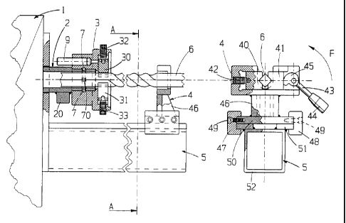
- Figure 1 is a fragmentary side view, partially cross-sectioned, of a
-2-

~~
CA 02284427 2004-O1-15
:)
twisting machine according to this invention when a square cross-section bar
is being worked.
- Figure 2 is a cross-section view taken along line A-A in Figure 1.
In the figures there are shown a twisting machine designated in general as 1,
a
hollow mandrel 2 of the twisting machine, an independent jaw chuck 3, a
counteracting support 4, and a prismatic guide 5.
As shown in figure I, a bar 6 to be twisted is centered between the chuck 3
and the counteracting support 4.
Only by way of example, the independent jaw chuck 3 comprises a pair of
1o jaws 30, 31, which have right-angled gripping surfaces and are approachable
along a vertical straight movement. The movement of the jaws 30, 31 is
controlled by their threaded connection means, i.e. adjusting screws 32, 33.
Further, by way of example, the counteracting support 4 is a vice chuck
comprising a pair of jaws 40, 41, which have right-angled gripping surfaces
and are approachable along a horizontal straight movement. The one jaw 40 is
controlled by a threaded connection means 42 in order to make possible that a
r
reference position is fixed depending on a bar to be worked. The other jaw 41
is controlled by an eccentric rod 43 having a handle control 44 and an
eccentric 45. The eccentric rod 43 can be operated in the direction of an
2o arrow F in order to move away the jaw 41 from the bar 6 to be worked.
The counteracting support 4 has an upright 46 and, at its bottom, means of
running fit with the prismatic guide 5. Such a means of running fit are
obtained for example by opposite U-shaped profiles 47, 48, which are
connected by screws 49 to a base plate 50 and are free to slide on a lower
rail
51 fixed to a tubular element 52 connected to a machine body, both the lower
-3-


CA 02284427 1999-09-30
rail 51 and the tubular element 52 constituting the prismatic guide 5.
According to the invention, the independent jaw chuck 3 comprises
cooperating means of rotary connection to the hollow mandrel 2 and means of
mutually engagement with the hollow mandrel 2.
In an embodiment of the invention said means of rotary connection consist of
circumferential grooves having a semicircular cross-section (not denoted by
numeral), which are carried out on the external surface of the mandrel 2 and
correspondingly on the internal cylindrical surface of the chuck 3 so that the
grooves are facing in order to function together as a ball race for balls 7,
as in
1o a re-circulating ball device. The circumferential groove of the chuck 3 is
communicating with a diametral hole 70 carried out into said groove, said
diametral hole being threaded and open into outside for the introduction of
the balls and the subsequent closure by means of a security dowel (not
shown).
Yet in an embodiment preferred at present, the above said means of mutually
engagement are constituted by an abutment projection 20 diametrically
projecting from and integral with the mandrel, and' a longitudinal pin 9
connected to the chuck. The means of mutually engagement are adapted to
rotate the chuck 3 by means of the mandrel 2, after a free rotation of the
2o chuck along an arc with an angle less than a round angle. In another
embodiment (not shown) the chuck has a slot extended along a certain arc of
circumference in which a pin connected to the mandrel is housed. However, a
person skilled in the art can conceive other rotary connections between the
mandrel and the chuck.
Although not shown, a revolution counter of the mandrel 2 in the form of a
-4-


CA 02284427 1999-09-30
stop microswitch device, by which a number of revolutions may be set in
order to achieve a desired twisting effect, can be joined to the twisting
machine according to the invention.
The operation of the machine is as follows. In a first step a bar 6 to be
twisted
is centered readily between the chuck 3 and the counteracting support 4 as the
chuck is "idle" or freely rotating on the mandrel 2. In a next step a twisting
operation, which is enabled by the driving engagement between the mandrel 2
and the chuck 3 through the longitudinal pin 9 of the chuck 3 and the
abutment projection 20 of the mandrel 2. In a third step the twisted bar is
to removed from the machine. For this purpose the machine turns the bar in the
opposite direction to the twisting direction, until the elastic limit of the
material of the bar is exceeded. By virtue of the chuck 3 freely rotating on
the
mandrel 2, the twisted bar is able to be removed from the machine.
The invention so conceived is liable to changes and modification without
departing from the scope of the same innovative concept. For example,
instead of the free rotation of the mandrel-chuck unit, the counteracting
support unit, comprised of the vice chuck and the upright, may be designed to
freely rotate. Further, the relative position of the independent jaw chuck and
counteracting support may be specularly opposed to that one as described and
2o shown. This invention is applicable also in this arrangement of the
machine.
Further, all the details may be replaced by technically equivalent elements.
-5-

Representative Drawing
A single figure which represents the drawing illustrating the invention.
Administrative Status

For a clearer understanding of the status of the application/patent presented on this page, the site Disclaimer , as well as the definitions for Patent , Administrative Status , Maintenance Fee  and Payment History  should be consulted.

Administrative Status

Title Date
Forecasted Issue Date 2004-12-14
(22) Filed 1999-09-30
Examination Requested 1999-09-30
(41) Open to Public Inspection 2000-04-01
(45) Issued 2004-12-14
Deemed Expired 2010-09-30

Abandonment History

There is no abandonment history.

Payment History

Fee Type Anniversary Year Due Date Amount Paid Paid Date
Request for Examination $400.00 1999-09-30
Registration of a document - section 124 $100.00 1999-09-30
Application Fee $300.00 1999-09-30
Maintenance Fee - Application - New Act 2 2001-10-01 $100.00 2001-09-24
Maintenance Fee - Application - New Act 3 2002-09-30 $100.00 2002-09-25
Maintenance Fee - Application - New Act 4 2003-09-30 $100.00 2003-09-16
Registration of a document - section 124 $100.00 2004-09-16
Final Fee $300.00 2004-09-16
Maintenance Fee - Application - New Act 5 2004-09-30 $200.00 2004-09-16
Maintenance Fee - Patent - New Act 6 2005-09-30 $200.00 2005-09-12
Maintenance Fee - Patent - New Act 7 2006-10-02 $200.00 2006-08-03
Maintenance Fee - Patent - New Act 8 2007-10-01 $200.00 2007-08-31
Maintenance Fee - Patent - New Act 9 2008-09-30 $200.00 2008-09-16
Owners on Record

Note: Records showing the ownership history in alphabetical order.

Current Owners on Record
CML INTERNATIONAL S.P.A.
Past Owners on Record
C.M.L. COSTRUZIONI MECCANICHE LIRI S.R.L.
CAPORUSSO, ALESSANDRO
CAPORUSSO, MARIO
Past Owners that do not appear in the "Owners on Record" listing will appear in other documentation within the application.
Documents

To view selected files, please enter reCAPTCHA code :


To view images, click a link in the Document Description column. To download the documents, select one or more checkboxes in the first column and then click the "Download Selected in PDF format (Zip Archive)" or the "Download Selected as Single PDF" button.

List of published and non-published patent-specific documents on the CPD .

If you have any difficulty accessing content, you can call the Client Service Centre at 1-866-997-1936 or send them an e-mail at CIPO Client Service Centre.


Document
Description 
Date
(yyyy-mm-dd) 
Number of pages   Size of Image (KB) 
Representative Drawing 2000-03-16 1 15
Claims 2003-05-30 4 170
Cover Page 2000-03-16 1 45
Abstract 1999-09-30 1 22
Description 1999-09-30 5 196
Claims 1999-09-30 2 57
Drawings 1999-09-30 1 30
Claims 2004-01-15 4 124
Description 2004-01-15 5 196
Representative Drawing 2004-11-16 1 18
Cover Page 2004-11-16 1 49
Prosecution-Amendment 2004-01-15 7 212
Assignment 2004-09-16 1 31
Correspondence 2004-09-16 1 33
Assignment 2004-09-16 30 1,302
Fees 2004-09-16 1 34
Assignment 1999-09-30 5 171
Prosecution-Amendment 2000-03-03 1 22
Prosecution-Amendment 2003-01-16 2 36
Prosecution-Amendment 2003-05-30 6 242
Prosecution-Amendment 2003-07-31 2 40
Fees 2003-09-16 1 32
Fees 2002-09-25 1 34
Fees 2001-09-24 1 28
Fees 2005-09-12 1 27
Fees 2006-08-03 1 29
Fees 2007-08-31 1 32
Fees 2008-09-16 1 37