Note: Descriptions are shown in the official language in which they were submitted.
CA 02284432 2003-12-04
MOUNTING A FINGER ON THE BAT OF A HARVESTING HEADER
This invention relates to a crop harvesting header of the type including
a pickup reel and particularly to an arrangement for mounting a finger on the
support
tube of a bat of the reel.
BACKGROUND OF THE INVENTION
The conventional harvesting header comprises a frame for mounting
on a crop harvesting machine for movement across ground carrying a crop to be
harvested, the frame defining a working width of the header, a table mounted
on the
frame across the width of the header for receiving the crop when cut for
transportation along the header, a cutting knife along a front edge of the
table for
cutting the crop and a pickup reel mounted above the knife and the table for
controlling the crop as it moves onto the table. The reel comprises a main
elongate
support beam and a plurality of bats at angularly spaced positions around the
main
beam.
A reel of this type is shown in U.S. Patent 4,776,155 assigned to the
present assignee. The bat comprises a tube formed from shaped sheet metal and
defining a cylindrical section along one edge of the tube so that the
cylindrical
section can be connected end to end to other such bats by short connecting
pipe
sections. The pipe sections and the cylindrical section thus define an axis
around
which the bat rotates. Each finger is inserted into a pocket defined in the
sheet
metal tube so as to project outwardly in a radial plane of the axis. Each
finger is
formed from a moulded plastics element defining a single thickness with a
slight
curvature toward the tip. A button on one end of the finger projects into a
hole in the
CA 02284432 2003-12-04
2
tube to latch the finger in place.
In an alternative construction also previously used, which supersedes
that shown in the above patent, there is provided a main longitudinal tube
forming
the base structure of the bat onto which is welded a plurality of sheet metal
holders
each for holding a finger of the construction shown in the patent.
These arrangements have some disadvantage in that the sheet metal
elements are relatively expensive and in that they mount only a single
thickness or
strip of the finger so that there is a tendency of the finger to break at or
adjacent the
edge of the sheet metal element.
A less expensive construction comprises a coiled wire arrangement
which defines two parallel spaced fingers connected by a central helical coil
section
which wraps around the tube. The central coil section is then bolted to the
tube by a
bolt which passes through diametrically opposed punched holes in the tube. The
head of the bolt thus holds down the central section of the coil thus holding
the coil
in place and maintaining the fingers at a predetermined angular orientation
around
the axis of the tube.
This arrangement has some disadvantage in that, while it is cheap and
easy to manufacture, the use of metal parts on the reel is disadvantageous in
that
any broken fingers or pieces of finger which enter the crop material pass into
and
through the combine harvester on which the header is mounted with significant
danger of damage to the threshing system.
Another prior art construction manufactured by HCC Inc of Mendota
Illinois comprises a moulded plastic finger which has integrally moulded with
the finger
CA 02284432 2003-12-04
3
portion a mounting portion in the form of a collar. The collar wraps wholly
around the
tube and is squeezed in place by a screw which clamps together two ends of the
collar.
In order to prevent rotation of the collar on the tube, there is provided a
single moulded
projection extending radially inwardly from an otherwise cylindrical surface
of the collar
so as to engage into a hole in the tube. This arrangement has the disadvantage
in that
it is relatively weak. It is desirable to provide a mounting which allows a
user to attach
either the wire coil arrangement or the plastic finger depending upon the
requirements in
particular crop conditions.
SUMMARY OF THE INVENTION
It is one object of the present invention to provide an improved
arrangement for mounting a finger on the support tube of a bat of a harvesting
header reel.
According to a first aspect of the invention there is provided a bat of a
reel of a harvesting machine comprising:
a support tube for extending longitudinally of an axis of the bat;
a plurality of fingers mounted on the tube so as to extend generally
outwardly from the tube in a radial plane of the axis;
the support tube having a plurality of finger support locations thereon
arranged at spaced locations along the axis with each finger arranged at a
respective one of the support locations along the length of the bat;
each finger including a finger portion and a mounting portion carried on
the tube from which the finger portion extends;
each finger including the finger portion and the mounting portion being
CA 02284432 2003-12-04
4
molded integrally from a plastics material;
each support location of the tube including two diametrically opposed
indentations punched into a wall of the tube so that the indentations are
recessed
from an outside surface of the wall of the tube and with each indentation
including a
hole formed through the wall of the tube;
the mounting portion of each finger comprising a collar at least partly
surrounding the tube at the support location, two projections on the collar
extending
radially inwardly from the collar and each engaging into a respective one of
the
indentations;
each projection comprising a first portion which projects into the
respective indentation in the wall and a second portion which is cylindrical
and
projects through the respective hole in the wall;
each of the projections having a hole through the first and second
portions thereof so as to be aligned with the hole in the wall;
and a fastener extending through the holes in the tube and through the
holes in the projections so as to engage the collar at the projections for
pulling the
projections radially inwardly to hold the projections in the respective
indentations to
hold the collar on the tube.
Preferably the collar extends only partly around the tube leaving an
open portion and wherein the collar is molded from a plastics material which
is
resiliently deformable allowing the open portion to be opened further by
flexing of the
collar to engage the collar and the projections around the tube.
Preferably the finger portion is attached to the collar at a position
CA 02284432 2003-12-04
adjacent one of the projections and is spaced from the other of the
projections to
leave a portion of the collar adjacent the other of the projections which can
flex.
Preferably the open portion extends substantially wholly from one
projection to the other projection.
5 Preferably the first portion of each of the projections comprises a
frusto-conical portion converging radially inwardly relative to the collar
from an outer
end at the collar to an inner end.
Preferably the fastener is a bolt extending through the holes and
carrying a nut to clamp the projections into the indentations.
Preferably the finger portion is shaped in cross-section adjacent the
collar to form an edge flange lying in a plane parallel to the axis and a web
at right
angles to the edge flange.
Preferably the finger portion is attached to the collar at a position such
that the edge flange is immediately adjacent one of the projections and the
finger
portion is spaced from the other of the projections to leave a portion of the
collar
adjacent the other of the projections which can flex.
Preferably the finger portion is shaped in cross-section adjacent the
collar to form a second edge flange lying in a plane parallel to the axis and
at right
angles to the web.
According to a second aspect of the invention there is provided a bat of
a reel of a harvesting machine comprising:
a support tube for extending longitudinally of an axis of the bat;
a plurality of fingers mounted on the tube so as to extend generally
CA 02284432 2003-12-04
6
outwardly from the tube in a radial plane of the axis;
the support tube having a plurality of finger support locations thereon
arranged at spaced locations along the axis with each finger arranged at a
respective one of the support locations along the length of the bat;
each finger including a finger portion and a mounting portion carried on
the tube from which the finger portion extends;
each finger including the finger portion and the mounting portion being
molded integrally from a flexible plastics material;
each support location of the tube including two diametrically opposed
indentations punched into a wall of the tube so that the indentations are
recessed
from an outside surface of the wall of the tube and with each indentation
including a
hole formed through the wall of the tube;
the mounting portion of each finger comprising a collar at least partly
surrounding the tube at the support location, two projections on the collar
extending
radially inwardly from the collar and each engaging into a respective one of
the
indentations;
and a fastener extending through the holes in the tube and engaging
the projections for pulling the projections radially inwardly to hold the
projections in
the respective indentations to hold the collar on the tube;
wherein the finger portion is attached to the collar at a position such
that the finger portion is immediately adjacent one of the projections and the
finger
portion is spaced from the other of the projections to leave a portion of the
collar
between the finger portion and the other of the projections which can flex.
CA 02284432 2003-12-04
7
According to a third aspect of the invention there is provided a finger
for a bat of a reel of a harvesting machine comprising:
a finger portion and a mounting portion from which the finger portion
extends;
the finger portion and the mounting portion being molded integrally
from a flexible plastics material;
the mounting portion of each finger comprising an annular collar for at
least partly surrounding a tube of the bat;
the finger portion lying in a common plane with the collar such that in
use the finger portion lies in a radial plane of the tube;
the collar having two diametrically opposed projections on the collar
extending radially inwardly from the collar for engaging into a respective one
of two
the indentations on the tube;
each projection comprising a first frusto-conical portion extending
radially inwardly relative to the collar from an outer end at the collar to an
inner end
and a second portion extending radially inwardly from the inner end of the
first
portion, the second portion being cylindrical with a cylinder axis extending
radially
inwardly relative to the collar;
at least one of the projections having a hole therethrough extending
radially inwardly relative to the collar and extending through the first and
second
portions thereof for receiving a fastener extending therethrough.
According to a fourth aspect of the invention there is provided a finger
for a bat of a reel of a harvesting machine comprising:
CA 02284432 2003-12-04
a finger portion and a mounting portion from which the finger portion
extends;
the finger portion and the mounting portion being molded integrally
from a flexible plastics material;
the mounting portion of each finger comprising an annular collar for at
least partly surrounding a tube of the bat;
the finger portion lying in a common plane with the collar such that in
use the finger portion lies in a radial plane of the tube;
the collar having two diametrically opposed projections on the collar
extending radially inwardly from the collar for engaging into a respective one
of two
the indentations on the tube;
at least one of the projections having a hole therethrough extending
radially inwardly relative to the collar and extending through the first and
second
portions thereof for receiving a fastener extending therethrough;
wherein the finger portion is attached to the collar at a position such
that the finger portion is immediately adjacent one of the projections and the
finger
portion is spaced from the other of the projections to leave a portion of the
collar
between the finger portion and the other of the projections which can flex.
BRIEF DESCRIPTION OF THE DRAWINGS
One embodiment of the invention will now be described in conjunction
with the accompanying drawings in which:
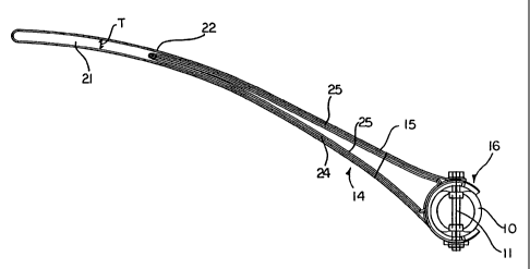
Figure 1 is a side elevational view of one bat of a reel according to the
present invention.
CA 02284432 2003-12-04
9
Figure 2 is a top plan view of a part only of the bat of Figure 1.
Figure 3 is a cross sectional view along the lines 3-3 of Figure 2.
Figure 4 is a cross sectional view along the lines 4-4 of Figure 2.
Figure 5 is a cross sectional view along the lines 5-5 of Figure 4.
In the drawings like characters of reference indicate corresponding
parts in the different figures.
DETAILED DESCRIPTION
A bat for the reel of a harvesting machine comprises an elongate tube
having a longitudinal axis 11. In general, the tube is mounted so that its
axis
10 extends along the length of the bat with a plurality of bats arranged at
angularly
spaced positions around the axis of the reel. The tubes are mounted each for
pivotal movement about the axis 11 as described in more detail in the above
United
States Patent 4,776,155.
As these elements of the bat and the reel are well known from the prior
art and can be varied in accordance with various design arrangements well
known to
one skilled in the art, no detailed description is provided in this
application.
The tube 10 of the bat has a plurality of finger mounting locations 12,
13 etc. at each of which is mounted a respective one or plurality of bat
fingers 14.
Each finger comprises an elongate finger portion 15 and a mounting portion 16
which attaches the finger portion to the tube.
At each finger mounting location, the tube has two punched holes 17
and 18 at diametrically opposed positions in the wall of the cylindrical tube.
Each
hole is punched to form an indentation 19 in which the wall of the tube is
indented
CA 02284432 2003-12-04
inwardly toward the axis 11 and a hole 20 located at the innermost part of the
indentation 19. Thus the punched holes 17 and 18 are aligned so a single
fastener
can pass through the holes.
The finger portion 15 includes an outermost part 21 which is tapered to
5 a single thickness so its cross section is defined by a simple rectangular
shape
which reduces in width while the thickness T remains substantially constant.
At a location indicated at 22, the cross sectional shape of the finger
portion changes from the rectangular shape of the portion 21 to a shape which
is
substantially I-shaped. Thus the shape is shown in cross section in Figure 5
10 including a top flange 23 and a bottom flange 24 together with a web 25
joining the
flanges. The height of the web 25 as best shown in Figure 1 increase from the
apex
at the point 22 down to the mounting member 16 to form a generally triangular
shape. The I-shaped cross section of the finger towards its root at the
mounting
member significantly increases the strength and reduces the possibility of
breakage
through the thickness of the finger in the area of I-shaped cross section.
The mounting member 16 comprises a collar 30 which is generally of
cylindrical shape with a cylindrical outer surface 31 and a generally
cylindrical inner
surface 32. The collar extends however only partly around the tube so that its
inside
surface 32 matches the outside surface of the tube. Thus the collar terminates
at a
first edge 33 and at a second edge 34. The collar extends through an angle
more
than 180° around the tube but less than 360° so that there is an
open space
befinreen the edges 33 and 34. In practice the collar extends around
approximately
240° leaving the open spaces as 120°.
CA 02284432 2003-12-04
11
The collar is moulded integrally with the root of the finger portion so
that each of the flanges 23 and 24 converges smoothly into the outside surface
of
the collar. The web 25 is also attached to the collar and extends around the
collar
between the flanges 23 and 24. This mounting provides a structurally rigid
connection between the finger and the collar which is resistant to breakage.
The collar has on its inside surface two projecting elements 35 and 36
which are arranged diametrically opposed. Each projecting element has a hole
37
passing through the projecting element and through the collar to be exposed on
the
outside surface 31. The projecting elements and the holes are diametrically
opposed
and radially inwardly extending relative to the collar so that each is coaxial
about an axis
39 extending through the collar at right angles to the axis 11. Each of the
projections
has a second portion in which generally cylindrical in shape so as to fit into
and through
the hole 20 in the tube. Each of the projections has a frusto-conical base or
first portion
so as to fit into the indentation 19.
The open space between the edges 33 and 34 allows the collar to be
flexed to an open position where it can pass over the outside of the tube.
Thus the
projections 35 and 36 are stretched outwardly by flexing of the collar to a
position
where they can pass over the diameter of the outside surface of the tube
allowing them
to slide to a position where they pop into the respective indentation and
hole. A bolt 40
is then passed through the aligned holes 37 so that a head 41 of the bolt
engages the
outer face 31 of the collar at one of the holes 37 and a nut 42 engages the
outer face 31
at the other of the holes. The bolt is threaded at a threaded end 43 allowing
the nut to
be clamped tight squeezing the projections inwardly into the indentations and
holes in
CA 02284432 2003-12-04
12
the tube. Thus the structure is relatively rigid and is held in place by two
projections into
the tube. The bolt preferably passes through both holes in the collar. However
in an
alternative arrangement (not shown) a self-tapping screw can be used which
passes
through the hole 37 of a first projection and taps a thread into the hole at
the projection
other side of the collar.
The flange 23 attaches to the collar 30 at a position immediately
adjacent the projection 35 so that the flange 24 connects to the collar at a
position
spaced away from the projection 36. This leaves a flexible portion of the
collar
between the edge 34 and the flange 24 which can flex outwardly to allow the
collar
to be inserted in place onto the tube.
This construction allows easy installation of the finger while using the
two existing holes that are required for the steel fingers.
The compression flange 23 is made wider than the tension flange to
prevent buckling of the compression flange under load, causing the finger to
twist
and bend sideways, and making the finger ineffective at pulling crop into the
header.
The design provides more uniform stresses in finger than prior art
when loaded by crop.
The finger is longer than competition allowing it to flex over foreign
objects and allowing it to work at a thicker mat of lodged crop before the
finger tube
compresses the crop.
Since various modifications can be made in my invention as herein
above described, and many apparently widely different embodiments of same made
within the spirit and scope of the claims without departing from such spirit
and
CA 02284432 2003-12-04
13
scope, it is intended that all matter contained in the accompanying
specification shall
be interpreted as illustrative only and not in a limiting sense.