Note: Descriptions are shown in the official language in which they were submitted.
CA 02284537 1999-09-20
- 1 -
"Apparatus for securing electrical cables"
The present invention relates to an apparatus
for securing electrical cables, which have a screen
for
electromagnetic compatibility (EMC), having a retaining
body and a contact-maker device, in which case the
contact-maker device is arranged inside the retaining
body and an electrical connection can be produced
between the screen and the retaining body by means of
the contact-maker device, in which case, in the
operating state, the screen is fixed in a force-fitting
manner, in particular being clamped, by me ans of
a
tightening element, which acts radially inwards,
between the contact-maker device and the retaining
body.
Electromagnetic compatibility (EMC) of
equipment or cables is becoming evermore important with
regard to the increasing use, both commercially and in
the private field, of electrical or electronic
equipment and machines which influence one another by
virtue of interference radiation.
Electrical cables equipped with a screen
prevent the emission of electromagnetic radiation,
since the interference radiation emitted, for example,
by the equipment or the assembly, is reliably
dissipated to zero potential via the screen. EMC-proof
cable installations comprise cable unions which allow
an electrical connection to be made between the screen
and the equipment housing.
By way of example, a cable union is known in
practice, which is equipped with a contact-maker device
within the retaining body, in order to produce the
electrical connection between the screen and the
retaining body. The contact-maker device comprises two
conical rings and an endless spring washer. When the
compression screw is tightened, the two conical rings
act radially inwards onto the spring washer. This
reduces the diameter of the spring washer, and the
AMENDED SHEET
CA 02284537 1999-09-20
- 2 -
screen makes contact with the cable passing through,
whose outer casing has been removed in the contact
region. Any electromagnetic interference radiation is
passed from the metallic retaining body, via the
metallic conical rings and the metallic spring washer,
to the screen and, finally, to zero potential.
A problem with this apparatus is that, in
mechanical terms, the contact to the screen is produced
only by the spring washer resting against the screen.
Even a slight reduction in the pressure exerted by the
compression screw on the conical rings the [sic] can
lead to an interruption in the contact, since the
diameter of the spring washer again increases.
Furthermore, the production and assembly of the known
apparatus or EMC cable union are quite complex owing to
the three components - namely two conical rings and a
spring washer.
EP 0 598 261 A2 discloses a solution to the
problem of securing the electrical contact between the
screen and the retaining body by the screen making
direct contact with the retaining body and being
clamped between the contact-maker device and the
electrically conductive retaining body. For this
purpose, the screen mesh is exposed and the contact-
maker device is then pushed on. The mesh is then bent
back, and the clamping process is carried out by means
of the retaining body and a tightening element. The
clamping process takes place exclusively in the radial
direction with respect to the longitudinal axis of the
screw union. In addition, the screen must be bent
around the contact-maker device in a complex way, thus
resulting in an increased assembly effort for
connecting the cable to the cable screw union. The
retaining body and the screw sleeve have no end face.
With this prior art, which is known from
EP 0 598 261 A2, as the starting point, the invention
is based on the object of specifying an apparatus of
the type under discussion, which is functionally
AMENDED SHEET
CA 02284537 1999-09-20
- 3 -
reliable, results in low production costs and,
furthermore, reduces the assembly effort overall.
The above object is achieved by the features of
Patent Claim 1. According to this claim, an apparatus
of the type under discussion is designed in such a way
that the application of force produced by the
tightening element on the contact-maker device is
directed coaxially with respect to the longitudinal
axis of the retaining body, so that the screen is
pressed against the end face of the retaining body.
According to the invention, it has first of all
in principle been recognized that the assembly effort
can be reduced if there is no need to bend the screen
around to match the contact-maker device once the cable
insulation has been stripped off. Furthermore, it has
been recognized that there is no need to bend the
screen around if the tightening element applies force
to the contact-maker device not only radially but also
coaxially. The coaxially directed application of force
moves the contact-maker device towards the screen,
which is gradually pressed against the end face of the
retaining body and, in consequence, is fixed. The
preparation of the cable could, for example, be limited
to exposing the screen, in which case engagement
elements are then provided on the contact-maker device
which deform the mesh such that sufficient material is
available for clamping. Alternatively, the screen could
simply be pushed back and a bead could be formed,
against which the contact-maker device is pressed
coaxially - without any special engagement elements. In
any case, the screen preparation steps which result
from the of (sicJ the prior art of this generic type
and increase the assembly effort, comprising weaving
the mesh, bending it to the rear, and cutting off the
screen, are eliminated in the claimed teaching in
favour of reduced assembly effort and thus more cost-
effective production, while at the same time ensuring
the functional reliability of the claimed apparatus.
AMENDED SHEET
CA 02284537 1999-09-20
- 4 -
A particularly effective connection between the
contact-maker device and the screen is produced if the
contact-maker device engages in the mesh of the screen
and presses the latter against the inner surface,
virtually compressing it in the process. If the outer
casing of the cable is removed and the screen is just
exposed, special engagement elements are required on
the contact-maker device, which deform the mesh so that
sufficient material is available, which can be clamped
between the contact-maker device and the retaining
body.
It is of particular advantage with respect to a
contact-maker device of simple design and without any
special engagement elements for the screen to be pushed
back after the outer casing is removed from the cable,
so that it forms a bead. The bead extends at right
angles to the longitudinal axis of the cable and
parallel to the end face of the retaining body, and
offers a good surface for the contact-maker device to
act on.
In order to produce the clamped connection
between the contact-maker device and the retaining body
with the interposition of the screen, the tightening
element (which, as is known, is part of the retaining
body) is tightened, during which process pressure is
applied to the contact-maker device.
According to a preferred exemplary embodiment,
the tightening element is a union nut having an
internal thread which, at its end facing away from the
rest of the retaining body, has an internal design
which converges in the direction of this end. This
refinement in particular additionally leads to the
application of pressure to the contact-maker device,
which is directed radially inwards, being supplemented
by pressure which is directed coaxially with respect to
the longitudinal axis of the retaining body being
applied to the contact-maker device according to the
invention. The coaxial application of pressure, which
AMENDED SHEET
CA 02284537 1999-09-20
- 4a -
is directed at least parallel to the longitudinal axis,
results in the contact-maker device being moved towards
the screen which, as a result of the convergent
internal design, is gradually pressed against the end
face of the retaining body, and is fixed by it. As an
alternative to the union nut having a convergent
internal design, a stepped reduction in cross section
would also be possible. Furthermore, instead of a union
nut, it would also be possible to use a sleeve or cap
which is provided with compression screws acting
obliquely or at right-angles with respect to the
longitudinal axis and which internally has a
configuration of some other type to cause the contact-
maker device to move parallel to the longitudinal axis,
in the direction of the end face of the retaining body.
From the production point of view and with
respect to handling, the contact-maker device is
designed in a simple manner - namely as an integral,
essentially tubular insert. According to one preferred
exemplary embodiment, the entire apparatus according to
the invention has
AMENDED SHEET
CA 02284537 1999-09-20
- 5 -
essentially only two components - on the one hand the
retaining body with the tightening element, and on the
other hand the tubular insert.
Since a tightening element which is in the form
of a union nut has an internal thread which is screwed
onto the external thread of the rest of the retaining
body and different internal cross sections are thus
present, the contact-maker device has a first section
with an external cross section matched to the
tightening element and a second section with an
external cross section matched to the rest of the
retaining body.
Within the region of the tightening element, a
sealing ring could be provided which extends between
the cable and the first section of the contact-maker
device. The contact-maker device could have a special
configuration for the sealing ring, in which case the
application of pressure (as explained above) coaxially
and parallel to the longitudinal axis could also be
conducive to particularly effective sealing. According
to one refinement of the apparatus according to the
invention, the second section (which has a smaller
internal cross section) could be used as a stop for the
sealing ring that is seated on the first section. The
stop could be designed in the form of a circumferential
recess, groove or fillet with an acute angle, in which
case the free end of the recess, which preferably runs
to an acute angle, bores into the sealing ring in the
operating state and presses the latter against the
tightening element while, for its part, the compression
intensifies the contact of the sealing ring on the
adjacent surfaces and, on the other hand, a small
portion of displaced sealing ring material can extend
into the recess.
Expediently, the internal cross sections of the
second section of the contact-maker device and of the
sealing ring are matched to the external cross section
of the cable, in such a manner that, at least during
assembly, a small amount of play is present, that [sic]
CA 02284537 1999-09-20
- 6 -
the cable can be moved relative to the contact-maker
device and, possibly, relative to the sealing ring. In
order that the apparatus according to the invention can
be pushed uniformly onto the cable, the inner surfaces
of the sealing ring and of the second section are
aligned with one another.
With regard to secure and permanent fixing of
the screen, it has been found to be particularly
advantageous that the [sic) that end region of the
second section whose end face is to be pressed against
the screen and the retaining body is at a radial
distance from the inner surface of the retaining body.
The small cross-sectional area of the end region
increases the magnitude of the force to be transmitted.
However, in order to ensure that the contact-maker
device is always sufficiently robust, the second
section has associated reinforcing elements on its
outer surface, which are guided by the inner surface of
the retaining body. A further advantage which results
from the spacing in the end region of the second
section of the contact-maker device is that, in the
operating state, at least a small portion of the screen
extends into the space and thus also makes contact with
the inner side wall of the retaining body. Since the
metal mesh of the screen is plastically deformed when
the end region is pressed against the inner end wall of
the retaining body and, in addition, a portion of the
inner surface of the side wall of the retaining body is
also permanently made contact with, a contact surface
is created which makes permanent contact with the
retaining body, so that all the internal and external
interference radiation can be reliably dissipated.
The contact-maker device could, furthermore,
have on its outer surface an anti-rotation device,
which interacts with the retaining body, or its inner
surface. The anti-rotation device is preferably formed
by a portion which projects like a step on the second
section of the contact-maker device, which section
engages in a groove on the retaining body and
CA 02284537 1999-09-20
effectively prevents rotation of the contact-maker
device about the longitudinal axis in the retaining
body.
With regard to the materials, the retaining
body and the tightening element are composed, in a
known manner, of conductive material, namely metal. The
contact-maker device is preferably produced from
plastic, having regard to the material costs.
There are now various options for refining and
developing the teaching of the present invention in an
advantageous manner. In this context, reference is made
on the one hand to the claims that are subordinate to
Patent Claim 1, and on the other hand to the following
description of an exemplary embodiment of the
invention, with reference to the drawing. Generally
preferred refinements and developments of the teaching
will also be explained in conjunction with the
explanation of the said exemplary embodiment of the
invention. In the drawing,
Fig. 1 shows a partially longitudinally cutaway
illustration of a front view of an exemplary
embodiment of the apparatus according to the
invention,
Fig. 2 shows a side view of the exemplary embodiment
shown in Fig. 1,
Fig. 3 shows an enlarged illustration of a detail
from Fig. 1, with the contact-maker device
being located in the operating state, which
is shown purely schematically, and
Fig. 4 shows an exploded illustration of the front
views of the individual components of the
object from Fig. 1.
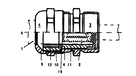
Figures 1, 3 and 4 show an apparatus for securing an
electrical cable 1, part of which is shown by dashed
CA 02284537 1999-09-20
- 8 -
lines and having conductors which are not shown in
detail and some of which are indicated just by dashed
lines. The cable 1 has a screen 2 for electromagnetic
compatibility (EMC). The apparatus comprises a
retaining body 3 and a contact-maker device 4, which is
arranged inside the retaining body 3 and, in principle,
has the object of producing an electrical connection
between the screen 2 and the retaining body 3.
In Figure 3, it can be seen that, in the
operating state, the screen 2 is fixed in a force
fitting manner between the contact-maker device 9 and
the retaining body 3, in this exemplary embodiment
being clamped. In this case, Figure 3 indicates only
purely schematically that the contact-maker device 4
engages in the mesh of the screen 2, and presses
against the inner surface of the retaining body 3 in
order to make contact. In particular, the screen 2
forms a bead 5 on which the contact-maker device 4
acts. The bead 5 is obtained after removal of the outer
casing of the cable 1 by stripping the screen 2 off, or
folding it back.
The retaining body 3 comprises a tightening
element 6 which, in the illustrated exemplary
embodiment, is a union nut. The tightening element 6
has an internal thread which is denoted by 7 in Figure
4 and is screwed onto a corresponding external thread 8
on the retaining body 3, with force being applied to
the contact-maker device 4 in order to produce the
clamping effect in the operating state. In order to
apply force to the contact-maker device 4 in the
coaxial direction with respect to the longitudinal axis
A (which is common in the operating state) of the
apparatus according to the invention, the tightening
element 6 has, at its end facing away from the rest of
the retaining body 3, a section 9 which is convergent
in the direction of this end. The section 9 presses the
contact-maker device 4 gradually against the bead 5 as
the tightening element 6 is progressively screwed to
the retaining body 3. Furthermore, in a known manner,
CA 02284537 1999-09-20
_ g _
the tightening element 6 causes a force, which is
directed radially inwards with respect to the
longitudinal axis A, to be applied to the contact-maker
device 4.
The contact-maker device 4 is essentially in
the form of a tubular insert which has a first section
with an external cross section matched to the
tightening element 6, and has a second section 11 with
an external cross section next to the retaining body 3.
10 The internal cross sections of the two sections 10 and
11 differ. A sealing ring 12 is seated on the larger
internal cross section of the first section 11 and its
internal cross section is aligned with that of the
second section 11 and, like this, is matched to the
external cross section of the cable 1.
As can be seen from Figures 1 and 4 a recess 13
with an acute angle is formed in the junction region
from the first section 10 to the second section 11 and
its free end 14, which runs to an acute angle, bores
into the sealing ring 12 in the operating state and
presses the latter against the tightening element 6,
while the displaced sealing ring material can extend
into the recess 13. Furthermore, an anti-rotation
device 18 (which is illustrated in Figure 4),
reinforcing elements 15 and an end region 16 are
provided on the outer surface of the second section 11
of the contact-maker device 4. The end region 16 is
pressed by the end face against the screen 2 and the
retaining body 3, and is at a radial distance from the
inner surface of the retaining body 3. In the assembled
state, the reinforcing elements 15 are supported
against the inner surface of the retaining body 3. When
the components have been assembled, the anti-rotation
device 18 engages in a cutout (which is not shown here)
on the inner surface of the retaining body 3, and thin
prevents the contact-maker device 4 from rotating in
the retaining body 3.
Furthermore, in order to provide sealing
between the contact-maker device 4 and the retaining
CA 02284537 1999-09-20
- 10 -
body 3, an 0-ring 19 (which is illustrated in Figure 1)
is provided, which is arranged to the side of the
contact-maker device 4 on the outer surface of the
junction region (which is stepped there) between the
first section 10 and the second section 11. In the
operating state, the free end of that section of the
retaining body 3 which has the external thread 8
presses the O-ring 19 into the step which is formed by
the larger external cross section of the first section
10 in comparison with the smaller external cross
section of the second section 11.
Furthermore, a groove 17 is provided in order
to accommodate an 0-ring for sealing ~-'~°w---- " -
on the external circumference of the retaining body 3.
Reference is made to the general part of the
description with regard to further features which are
not shown in the figures.
Finally, it should be mentioned that the
teaching according to the invention is not limited to
the exemplary embodiment described above. In fact, by
way of example, widely differing configurations are
possible for the contact-maker device which acts
between the screen and the retaining body. -