Language selection

Search

Patent 2284623 Summary

Third-party information liability

Some of the information on this Web page has been provided by external sources. The Government of Canada is not responsible for the accuracy, reliability or currency of the information supplied by external sources. Users wishing to rely upon this information should consult directly with the source of the information. Content provided by external sources is not subject to official languages, privacy and accessibility requirements.

Claims and Abstract availability

Any discrepancies in the text and image of the Claims and Abstract are due to differing posting times. Text of the Claims and Abstract are posted:

  • At the time the application is open to public inspection;
  • At the time of issue of the patent (grant).
(12) Patent: (11) CA 2284623
(54) English Title: MOVABLE MOLTEN MASS GUIDE SLEEVE TO COMPENSATE FOR TEMPERATURE-DEPENDENT EXPANSION BETWEEN THE HOT CHANNEL AND THE MOLD FEED ORIFICE
(54) French Title: MANCHON MOBILE DISTRIBUTEUR DE LA MATIERE PLASTIQUE FONDUE PERMETTANT DE COMPENSER LA DILATATION THERMIQUE ENTRE LE CANAL DE CAROTTE CHAUFFE ET L'ENTREE DU MOULE
Status: Deemed expired
Bibliographic Data
(51) International Patent Classification (IPC):
  • B29C 45/27 (2006.01)
(72) Inventors :
  • CHRISTEN, ANDREAS (Switzerland)
(73) Owners :
  • PROTOOL AG (Switzerland)
(71) Applicants :
  • PROTOOL AG (Switzerland)
(74) Agent: FETHERSTONHAUGH & CO.
(74) Associate agent:
(45) Issued: 2008-03-25
(86) PCT Filing Date: 1999-01-19
(87) Open to Public Inspection: 1999-07-29
Examination requested: 2003-12-16
Availability of licence: N/A
(25) Language of filing: English

Patent Cooperation Treaty (PCT): Yes
(86) PCT Filing Number: PCT/CH1999/000023
(87) International Publication Number: WO1999/037461
(85) National Entry: 1999-09-20

(30) Application Priority Data:
Application No. Country/Territory Date
134/98 Switzerland 1998-01-21

Abstracts

English Abstract


The invention relates to a dynamic molten mass guide sleeve
with an articulated motion to compensate for differences in
expansions in the inner flow hot channel with air gap
insulation in injection molding of plastics. To date, fixed
molten mass guide sleeves required extrremely stringent
location deviations and often led to mold cavity ruptures or
leakage as a result of differences in expansions. The
inventive sleeve is fitted with peripheral sealing lips on
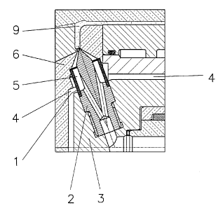
both ends and is mounted in-between the hot channel (3) and
the mold cavity (6). Said sleeve compensates for heat
expansions and enables well-defined temperature separation
in the mold feed orifice area of the injection mold by
sealing the air gap (4).


French Abstract

L'invention concerne un manchon dynamique distributeur de la matière plastique fondue, du type articulé, destiné à compenser les différences de dilatation dans le canal chauffant à écoulement interne isolé par des fentes d'aération, dans des moules d'injection pour transformer les matières plastiques. Les manchons de ce type, ancrés à demeure, revendiqués jusqu'à présent, présentaient des tolérances de montage extrêmement serrées et entraînaient souvent une rupture d'empreinte ou bien des fuites par suite de différences de dilatation. Le manchon décrit dans la présente invention, lequel comporte des lèvres d'étanchéité périphériques à ses deux extrémités et est monté entre le canal chauffant (3) et l'empreinte (6), compense le phénomène de dilatation thermique et permet, grâce à une étanchéification de la fente d'aération (4) une séparation thermique plus nette dans la région de l'entrée du moule d'injection.

Claims

Note: Claims are shown in the official language in which they were submitted.


CLAIMS:


1. An injecting molding apparatus having a molten mass guide
sleeve for delivering molten thermoplastic material to a
mold cavity through an insulating air gap between a hot flow
runner system and the mold cavity wherein the molten mass
guide sleeve is movably disposed between the hot flow runner
system and the mold cavity to accommodate differential
expansion between the hot flow runner system and the mold
cavity, wherein the hot flow runner system includes a heated
nozzle body and the molten mass guide sleeve comprises a
connecting device for guiding the thermoplastic plastic
material from the heated nozzle body to the cooler mold
cavity essentially without leakage of molten thermoplastic
material.

2. The injection molding apparatus having a molten mass
guide sleeve according to claim 1, wherein the molten mass
guide sleeve is operable to accommodate internal pressures
up to 2,500 bar and temperature differences up to 4000
Celsius.

3. The injection molding apparatus having a molten mass
guide sleeve according to claim 2, wherein the molten mass
guide sleeve is loosely mounted between said hot flow runner
system and the mold cavity and further comprising a
circumferential seal at each end thereof.

4. The injection molding apparatus having a molten mass
guide sleeve according to claim 3, wherein said
circumferential seal further comprises a circumferential
cambered sealing lip at each end of said molten mass guide
sleeve.

5. The injection molding apparatus having a molten mass
guide sleeve according to claim 3, wherein the internal


6

pressure is operable to expand the molten mass guide sleeve,
thereby providing a circumferential sealing action at each
of cambered ends.

6. The injection molding apparatus having a molten mass
guide sleeve according to claim 3, wherein said
circumferential seals are operable to compensate for
geometrical irregularities in the hot runner system and the
mold cavity caused by differential expansion.

Description

Note: Descriptions are shown in the official language in which they were submitted.


CA 02284623 2004-03-04
23444-394

1
MOVABLE MOLTEN MASS GUIDE SLEEVE TO COMPENSATE FOR
TEMPERATURE DEPENDENT EXPANSION BETWEEN THE HOT CHANNEL AND

THE MOLD FEED ORIFICE
Field of the Invention

The present invention relates to hot runner
systems for use in injection molding systems in connection
with the treatment of thermoplastic materials.

Background

Prior art systems have used rigidly mounted molten
mass guide sleeves. The expansion of such guide sleeves
must be calculated very precisely. This application
requires extremely stringent mounting tolerances and often
lead to mold cavity ruptures or leakage as a result of
temperature differences. Moreover, higher temperatures may
lead to ruptures since there is not enough room for the
expansion. In addition, lower temperatures may lead to
leakage since it results in excessive play between the
sealing lip and the feed orifice of the mold cavity.
Brief Description of the Drawings

FIG. 1 depicts a molten mass guide sleeve in an
obliquely oriented section;

FIG. 2 depicts a molten mass guide sleeve in a
radially oriented section;

FIG. 3 depicts a molten mass guide sleeve in an
axially oriental section; and

FIG. 4 depicts a detail of a molten mass guide
sleeve according to the invention, wherein reference
numerals 11 and 13 refer to a hot runner area, and reference


CA 02284623 2004-03-04
23444-394

2
numerals 12 and 14 refer to a relatively colder mold cavity
area.

Detailed Description of the Invention

The present invention relates to the feed orifice
area used in an air gap insulated inner hot flow runner
system for the treatment of thermoplastic materials.

A hot flow runner system may be mounted in an
injection molding tool. In turn, the injection molding tool
is part of an injection molding machine. The injection
molding machine introduces molten thermoplastic materials
into the injection molding tool under high pressure (up to
2,500 bar) and at high temperatures (up to 4000 Celsius).
The hot molten mass is supplied through heated hot runner
system (3) to cooled or tempered mold cavity (6).

Consequently, a heated hot runner system (3) is
located adjacent a cooled mold cavity tool. The two parts
must be thermally separated without prejudice to flow

tightness.

In this regard, the better the insulation between
the hot flow runner system and the cooler mold cavity, the
better the operation of the hot flow runner.

The best possible thermal separation is provided
by the air gap (4).

As alluded to above, the temperature differential
between the hot runner system (3) and mold cavity (6 and 9)
may cause differential expansion between these parts.

Therefore, a molten mass guide sleeve (1)
according to the invention is used as a connecting piece


CA 02284623 2004-03-04
23444-394

3
positioned between the heated hot runner system (3) and the
cooler mold cavity (6 and 9).

The molten mass guide sleeve surrounds a needle of
the nozzle (2) which guides the molten mass (5) from the hot
runner system of the heated nozzle body (3) to the feed
ori f ice (9) in the mold cavity (6).

Heating causes relative movement, which is
absorbed by the molten mass guide sleeve (1) without losses
in tightness despite high internal pressures and high
temperature differences. The molten mass guide sleeve (1)
has cambered sealing li.ps at each end at the circumference
thereof.

The cylindrical outlet of the hot runner system of
the heated nozzle body and the cylindrical inlet of the
relatively cooler mold cavity form the two sealing elements
which cooperate with the molten mass guide sleeve. The
molten mass guide sleeve is loosely mounted so that it can
articulate between the heated nozzle body outlet and mold
cavity inlet.

In the case of multiple nozzles or lateral
thermoplastic feeding methods, minor geometrical errors due
to the expansion of the heated hot runner system are
inevitable. The outlet of the hot nozzle body may not be
exactly alligned with the inlet of the mold cavity.

This error is compensated by the molten mass guide
sleeve without any loss of tightness. In addition, the high
internal pressure executed by the thermoplastic slightly
inflates the sleeve and firmly presses the sealing elements
or lips against the circumference of the nozzle body outlet
and the mold cavity inlet, thus ensuring absolute tightness.


CA 02284623 2004-03-04
23444-394

4
This allows for greater distances between the zero
point of expansion of the nozzle body relative to the feed
orifice of the mold cavity as compared to prior art systems.

Representative Drawing
A single figure which represents the drawing illustrating the invention.
Administrative Status

For a clearer understanding of the status of the application/patent presented on this page, the site Disclaimer , as well as the definitions for Patent , Administrative Status , Maintenance Fee  and Payment History  should be consulted.

Administrative Status

Title Date
Forecasted Issue Date 2008-03-25
(86) PCT Filing Date 1999-01-19
(87) PCT Publication Date 1999-07-29
(85) National Entry 1999-09-20
Examination Requested 2003-12-16
(45) Issued 2008-03-25
Deemed Expired 2014-01-21

Abandonment History

There is no abandonment history.

Payment History

Fee Type Anniversary Year Due Date Amount Paid Paid Date
Registration of a document - section 124 $100.00 1999-09-20
Application Fee $150.00 1999-09-20
Maintenance Fee - Application - New Act 2 2001-01-19 $100.00 2000-12-19
Maintenance Fee - Application - New Act 3 2002-01-21 $100.00 2002-01-04
Maintenance Fee - Application - New Act 4 2003-01-20 $100.00 2002-12-13
Maintenance Fee - Application - New Act 5 2004-01-19 $150.00 2003-12-04
Request for Examination $400.00 2003-12-16
Maintenance Fee - Application - New Act 6 2005-01-19 $200.00 2004-12-14
Maintenance Fee - Application - New Act 7 2006-01-19 $200.00 2005-12-21
Expired 2019 - Corrective payment/Section 78.6 $150.00 2006-10-20
Maintenance Fee - Application - New Act 8 2007-01-19 $200.00 2006-12-28
Final Fee $300.00 2007-10-19
Maintenance Fee - Application - New Act 9 2008-01-21 $200.00 2007-12-21
Maintenance Fee - Patent - New Act 10 2009-01-19 $250.00 2009-01-15
Maintenance Fee - Patent - New Act 11 2010-01-19 $250.00 2010-01-07
Maintenance Fee - Patent - New Act 12 2011-01-19 $450.00 2011-10-06
Maintenance Fee - Patent - New Act 13 2012-01-19 $250.00 2012-01-06
Owners on Record

Note: Records showing the ownership history in alphabetical order.

Current Owners on Record
PROTOOL AG
Past Owners on Record
CHRISTEN, ANDREAS
Past Owners that do not appear in the "Owners on Record" listing will appear in other documentation within the application.
Documents

To view selected files, please enter reCAPTCHA code :


To view images, click a link in the Document Description column. To download the documents, select one or more checkboxes in the first column and then click the "Download Selected in PDF format (Zip Archive)" or the "Download Selected as Single PDF" button.

List of published and non-published patent-specific documents on the CPD .

If you have any difficulty accessing content, you can call the Client Service Centre at 1-866-997-1936 or send them an e-mail at CIPO Client Service Centre.


Document
Description 
Date
(yyyy-mm-dd) 
Number of pages   Size of Image (KB) 
Representative Drawing 1999-11-19 1 17
Cover Page 1999-11-19 2 73
Abstract 1999-09-20 1 22
Description 1999-09-20 4 110
Claims 1999-09-20 2 41
Drawings 1999-09-20 4 118
Claims 2004-03-04 2 61
Description 2004-03-04 4 134
Drawings 2007-02-13 2 75
Representative Drawing 2007-06-07 1 18
Cover Page 2008-02-21 1 53
Prosecution-Amendment 2003-12-16 1 42
Assignment 1999-09-20 4 142
PCT 1999-09-20 8 358
Prosecution-Amendment 2004-03-04 8 239
Fees 2005-12-21 1 34
Prosecution-Amendment 2006-08-15 2 34
Prosecution-Amendment 2006-10-20 2 50
Correspondence 2006-11-03 1 15
Prosecution-Amendment 2007-02-13 4 121
Correspondence 2007-10-19 1 38