Note: Descriptions are shown in the official language in which they were submitted.
CA 02284780 1999-09-24
- WO 98!42427 PCT/AU98/00204
LIQUID/GAS/SOLID SEPARATION
' The present invention relates to processing a
charge of solid material in a vessel under conditions which
include high mass flow rate of: gas through the vessel and
removal of gas from the vessel..
The present invention extends to processing solid
material by heating or by cooling.
The present invention relates particularly,
although by no means exclusively, to processing a charge of
solid material (which, optionally, has a low thermal
conductivity) in a vessel under conditions (which include
high pressure and temperature) that produce liquid from the
solid material and high mass flow rate of gas (produced
from the solid material and/or added to the vessel as part
of the process).
The present invention relates more particularly
to a process and an apparatus :for upgrading carbonaceous
materials, typically coal, particularly low rank coal,
under conditions which include high pressure and
temperature to increase the 8T17 value of the carbonaceous
materials by removing water from the carbonaceous
materials, which process and apparatus includes separating
solids, liquid, and gas phases produced by or supplied to
the process.
The following discussion of the prior art is in
relation to difficulties separating solids, gas and liquid
phases produced when coal is dewatered by heating the coal
under elevated pressure conditions. It is noted that in
more general terms the present invention extends to
CA 02284780 1999-09-24
WO 98/42427 PCT/AU98/00204
- 2 -
difficulties caused by high mass flow rate of gas through
vessels containing solids, with or without liquid present,
under heating or cooling conditions.
US patent 5,290,523 to Koppelman discloses a
process for upgrading coal by the simultaneous application
of pressure and temperature.
Koppelman discloses thermal dewatering of coal by
heating coal under conditions which include elevated
pressure and temperature to cause physical changes in the
coal that results in water being removed from the coal by a
"squeeze" reaction.
Koppelman also discloses maintaining the pressure
sufficiently high during the upgrading process so that the
by-product water is produced mainly as a liquid rather than
steam.
Koppelman also discloses a range of different
apparatus options for carrying out the upgrading process.
In general terms, the options are based on the use of a
pressure vessel which includes an inverted conical inlet, a
cylindrical body, a conical outlet with a single outlet at
the apex of the conical outlet, ie the lowest section of
the vessel, and an assembly of vertically or horizontally
disposed heat exchange tubes positioned in the body.
In one proposal to use a Koppelman-type
apparatus, the vertically disposed tubes and the outlet end
are packed with coal, and nitrogen is injected to
pressurise the tubes and the outlet end. The coal is
heated by indirect heat exchange with a heat exchange
medium supplied to the cylindrical body externally of the
tubes. Further heat is generated by supplying water to the
tubes, which subsequently forms steam that acts as a heat
transfer medium. The combination of elevated pressure and
CA 02284780 1999-09-24
WO 98/42427 PCT/AU98/00204
- 3 -
temperature conditions evaporates some of the water from
the coal and thereafter condenses some of the water as a
liquid. A portion of the steam generated following the
addition of water also condenses as a liquid due to the
elevated pressure. Steam which is not condensed, and which
is in excess of the requirements for optimum pressurisation
of the packed bed, must be ver.~ted. In addition, non-
condensable gases (eg CO, COz) are evolved and need to be
vented. Periodically, liquid is drained from the outlet
end. Finally, after a prescribed residence time, the
vessel is depressurised and the upgraded coal is discharged
via the same outlet end.
It has been found that the configuration of the
outlet end of the above-described Koppelman-type apparatus
has not been altogether satisfactory in terms of separating
the solid/liquid/gas phases anal, more particularly
liquid/gas phases. The problems encountered include high
pressure drop and high gas velocity in the outlet end which
results in:
(i) two phase flow of liquid and gas from the
outlet end that is difficult to control;
(ii) blockage preventing discharge; and
(iii)fines and sometimes coarse material being
discharged with liquid (and gas).
More particularly, i:n general terans, gas and
liquid exiting a vessel through the same outlet duct tend
to flow in a most irregular fashion due to the different
flow resistances of the gas and liquid in the bed, ducts
and control valves. The compressible nature of the gas,
the rapidly varying resistancea, and the comparatively high
density of the liquid leads to a flow with high
acceleration forces which can lead to disturbance and
CA 02284780 1999-09-24
WO 98/42427 PCT/AU98/00204
- 4 -
probable transport of particles in the packed bed.
One object of the present invention is to provide
improved separation of solids, liquid, and gas generated in
or supplied to the Koppelman-type apparatus.
A more general object of the present invention is
to provide an apparatus for separating solids, liquid, and
gas in pressure vessels operated at high pressures and
temperatures.
A further more general object of the present
invention is to provide an apparatus for introducing and/or
removing high mass flow rate of gas into and/or from
vessels containing solid material which is being processed
in the vessels.
The term "high" in the context of "mass flow rate
of gas" is understood herein as indicating that the total
amount of the gas is a significant proportion, typically 5-
10°%, of the mass of the solid material and/or that the mass
flow rate of gas approaches the threshold for fluidising
the solid material in the vessel.
In the broadest sense, the present invention
provides an improvement to a vessel for processing a charge
of solid material under conditions which include high mass
flow rate of gas through the vessel, the improvement
including providing the vessel with at least one solids
outlet for discharging solids from the vessel and a
plurality of gas inlets and/or gas outlets for introducing
gas into or discharging gas from the vessel at one or more
levels of the vessel above the gas outlet or outlets.
More particularly, according to the present
invention there is provided an improvement to a vessel for
processing a charge of solid material under conditions
CA 02284780 1999-09-24
WO 98/42427 PCT/AU98/00204
- 5 -
which include high mass flow :rate of gas through the vessel
and which produce liquid from the solid material, the
improvement including an outlet end of the vessel having at
least one solids outlet, at lesast one liquids outlet, and
at least one gas outlet, and t:he at least one gas outlet
being positioned above the at least one solids outlet and
the at least one liquid outlet:.
The aspect of the present invention described in
the preceding paragraph is basted on the realisation that
effective separation of solids, liquid, and gas from a
vessel, with minimum entrainme:nt of solids and gas with
liquid, can be achieved by providing separate removal~f
liquid and gas at different levels of the outlet end, and
with the gas outlet (or outleta) being at a higher level
than that of the liquid outlet. (or outlets).
This aspect of the present invention can also be
described as an apparatus for processing a charge of a
solid material under conditions which include high mass
flow rate of gas through the apparatus and which produce
liguid from the solid material, which apparatus includes:
(a) a vessel having:
(i) an inlet end having an inlet for
supplying the solid material to form a
packed bed in the vessel; and
(ii) an outlet end having at least one
solids outlet, at least one liquids
outlet, and at least one gas outlet
positioned above the solids/liquid
w outlets;
(b) a means for supplying a fluid to pressurise
the packed bed; and
CA 02284780 1999-09-24
WO 98/42427 PCT/AU98/00204
- 6 -
(c) a means for supplying a heat exchange medium
to heat the solid material.. in the packed
bed.
It is preferred that the outlet end be in a lower
section of the vessel.
It is preferred that the outlet end converges to
one (or possibly more) solids outlets.
It is preferred particularly that the outlet end
be conical.
It is preferred that the outlet end includes a
plurality of gas outlets.
It is preferred that the gas outlets be located
at more than one level of the outlet end.
It is preferred that there be a plurality of gas
outlets at least at one level of the outlet end.
Preferably, at each level that has a plurality of
gas outlets, the gas outlets are spaced around the
perimeter of the vessel so that across that level there is
substantially uniform downward mass flow rate of gas.
In more general terms, the number and location
and structure of the gas outlets is governed by:
(i) the need to progressively remove gas at
different levels down the outlet end such
that the mass flow per unit cross section
(or velocity) in the packed bed is
maintained approximately constant at each
level;
CA 02284780 1999-09-24
WO 98/42427 PCT/AU98/00204
(ii) the need to draw gas at each level towards a
gas outlet without creating regions of high
gas velocity which may lead to high pressure
drop and/or eni~rainment of solids and/or
liquid; and
(ii) the need to turn the gas flow from downward
to outward latE:ral flow whilst at the same
time allowing any liquid to continue in a
substantially downward direction.
It is noted that the: term "fluid" as used in_
paragraph (b) above is sufficiently broad to cover the use
of a gas, such as nitrogen, and a liquid, such as water,
introduced into the vessel.
It is preferred that the means for supplying the
heat exchange medium supplies the medium to heat the solid
material by indirect heat exchange.
It is preferred that the vessel be a pressure
vessel.
The above-described ;particular aspect of the
present invention can also be described as a process for
processing a charge of a solid material under conditions
which include high mass flow rate of gas and which produce
liquid from the solid material, which process includes:
(a) supplying the solid material to a vessel to
form a packed bed of the solid material;
(b) pressurising the packed bed;
(c) heating the solid material by heat exchange
with a heat exchange medium, whereby the
CA 02284780 1999-09-24
WO 98/42427 PCT/AIJ98/00204
_ g _
combined effect of pressure and heat is to
release water and other liquid and/or
gaseous compounds from the solid material,
with part of the released water being in a
gas phase and part of the water being in a
liquid phase;
(d) discharging gas from the packed bed via at
least one gas outlet in the vessel; and
(e) discharging liquid from the packed bed via a
liquid outlet in the vessel located below
the gas outlet.
The process may include introducing gas to the
vessel as a working fluid to contribute to heat transfer to
the solid material.
It is noted that step (d) of discharging gas may
include removal of an amount of liquid. It is also noted
that step (e) of discharging liquid may include removal of
an amount of gas.
It is preferred that the basis for discharging
gas from the packed bed be to control:
(l) the pressure drop in the outlet end; and/or
(ii) the flow of gas into the section of the
outlet end that is below the level of the
gas outlet.
It is preferred particularly that the process
includes discharging gas from the packed bed via a
plurality of gas outlets so that there is substantially
constant flow velocity of gas in the section of the outlet
end below the level of the gas outlets.
CA 02284780 1999-09-24
WO 98/42427 PCT/AU98/00204
- g _
It is preferred than the basis for discharging
liquid from the packed bed be the level of liquid in the
outlet end at any point in time during operation of the
process such that discharge v:ia the liquid outlet is
predominantly liquid.
It is preferred that: the process includes
discharging gas from the packed bed via gas outlets at two
or more levels above the liquid outlet.
It is preferred that. the process includes
discharging gas via a plurality of gas outlets at least at
one of the levels above the la.quid outlet.
It is preferred that the vessel includes an
outlet end that converges to one (or possibly more) solids
outlets.
It is preferred particularly that the vessel
includes a conical outlet end and that the gas outlet or
outlets and the liquid outlet be located in the outlet end.
The present invention is described further by way
of example with reference to the accompanying drawings of
which:
Figure 1 is a schematic diagram of an outlet end
of one preferred embodiment of an apparatus in accordance
with the present invention.
Figure 2 is a cross-section along the line 2-2 in
Figure 1;
Figure 3 is a schematic diagram of an outlet end
of another preferred embodiment of an apparatus in
accordance with the present invention;
CA 02284780 2005-06-09
- 10 -
Figure 4 is a plot of pressure drop along the
length of a vessel which was produced during computational
fluid dynamics ("cfd") modelling work carried out for the
applicant.
Figure 5 is a plot of mass flow rate at a level
3 m from the base of a vessel from the axial centreline to
the perimeter of the vessel which was produced during cfd
modelling work carried out for the applicant.
The following description is predominantly in
to the context of upgrading coal. It is noted that the
present invention is not so limited and extends to
processing any suitable solid material.
Furthermore, the following description is
predominantly in the context of the Koppelman-type
i5 apparatus described above. It is noted that the present
invention is not so limited and has general application to
processing solid material under elevated pressure and
temperature conditions which requires separation of solid,
liquid and gas during andjor at the end of the processing.
2o By way of further specific example, the present
invention extends to the apparatus (and the process?
described in International Publications No. WO 98/30856
and WO 98/39613 in the name of the applicant.
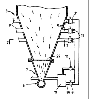
With reference to Figures 1 and 2, the apparatus
25 includes a pressure vessel having an outlet end, generally
identified by the numeral 3, in the form of a cone.
The outlet end 3 comprises:
CA 02284780 1999-09-24
- WO 98/42427 PCT/AU98/00204
- 1:L -
(l) a solids outlei~ 5 in the end of the cone;
(ii) a liquid outlet: 7 in a lower section of the
cone;
(iii) a plurality of gas outlets 9 at different
levels of the cone above the solids/liquids
outlets 5,7 and, as can best be seen in
Figure 2, with more than one gas outlet 9 at
each of the levels; and
(iv) optionally, a solids retentian means 2 ~.
It is noted that the present invention is not
limited to a conical outlet en.d and, by way of example,
extends to any outlet end that converges to one or more
solids outlets.
The above-described locations of the liquid/gas
outlets 7,9 enable separate liquid separation and gas
separation from liquid and gas that, in use, flow
downwardly through the vessel to the outlet end 3.
Specifically, the gas outlets 9 allow progressive removal
of gas as the gas flow converges in the cone towards the
lower end of the cone.
The solids/liquid/ga~a outlets 5, 7, 9 may be of
any suitable form.
In the case of the gas outlets 9, the outlets may
be in any suitable form and location bearing in mind the
need:
(l) to progressivel~;r remove gas at different
levels down the cone such that the mass flow
per unit transverse cross-section of the
CA 02284780 1999-09-24
WO 98/42427 PCT/AU98/00204
- 12 -
cone (or the velocity) in the packed bed is
maintained substantially constant at each
level; and
(ii) to draw gas at each level towards an outlet
means without creating regions of high gas
velocity which may lead to high pressure
drop and/or entrainment of solids and/or
liquids.
The preferred embodiment of the present
invention, as shown in Figure 2, includes a series of
discrete gas outlets 9 spaced around the perimeter of~he
vessel at a given level. This arrangement results in
general outward flow of part of the downwardly flowing gas
towards the perimeter of the vessel and thereafter from the
vessel via the outlets.
Alternatively, by way of example, there may be a
substantially continuous outlet (not shown) around the
perimeter of the vessel at each level which ensures that
there is a uniform outward movement of gas towards the
perimeter of the vessel.
The solids/liquid/gas outlets 5, 7, 9 include
valve means 11 that are selectively operable to allow
solids, liquids, and gas to discharge from the outlet end
3.
The valve means 11 are positioned as close as
possible to the vessel so that there is minimal duct work
between the vessel and the valve means to minimise mass
flux of gas through the outlet end during start-up.
The apparatus further includes a relatively small
holding tank 17 connected to the liquids outlet 7 for
receiving liquid discharged from the outlet end. The
CA 02284780 1999-09-24
WO 98/42427 PCT/AU98100204
- 1:3 -
holding tank 17 has an outlet line 19 in a lower section
which is controlled by a valve means 11. In use, liquid is
discharged from the holding tank 17 via the outlet line 19.
In use of the apparatus to dewater coal, a charge
of coal is supplied to the vessel and, more particularly to
the outlet end 3 and the tube;a (not shown) of the
apparatus. Thereafter:
(i) nitrogen is pumped into the packed bed of
coal in the tulbes and the outlet end 3 to
pressurise the packed bed, typically to a
pressure of 100-200 psi;
(ii) a heat exchange medium is supplied to the
vessel externa:Lly of the tubes to heat the
coal by indirect heat exchange, typically to
a temperature of 520°F; and
(iii) water is supplied to the packed bed to
provide a source of steam.
The steam produced in the packed bed from the
inlet feed of water contributes to the pressure in the
packed bed and provides a means for further heating of the
coal. In addition, as noted above, steam evolved from the
water in the coal also contributes to the pressure in the
packed bed. The combination of these factors pressurises
the packed bed to an operatin<~ pressure, typically 700 psi.
The combined effect of the elevated pressure and
temperature is to evaporate or squeeze water from the coal
in the packed bed and to condense the water at
progressively lower levels in the vessel. The ~~squeeze~~
reaction is caused by structural realignment of the coal
and also by decarboxylation reactions.
CA 02284780 1999-09-24
WO 98/42427 PCT/AU98/00204
- 14 -
The liquid collects in the outlet end 3 of the
vessel and periodically is removed via the liguid outlet 7
into the holding tank 17.
As discussed above, the location of the
solids/liquid/gas outlets 5, 7, 9 at different levels makes
it possible to have separate removal of solids, liquid, and
gas, and more particularly liquid and gas, from the outlet
end 3.
Moreover, the removal of gas from the vessel via
the gas outlets 9 separately to removal of the liquid makes
it possible to avoid high pressure drop in the outlet end
and high flow rates of gas in the lower section of the
outlet end 3.
With reference to Figure 3, in order to minimise
loss of liquid and solids via the gas outlets 9, one
preferred embodiment of the present invention includes
plates or screens 21 positioned in relation to the gas
outlets 9 to initially deflect downward flow of solids,
liquids, and gas away from the gas outlets 9. In addition,
the plates/screens 21 define downwardly opening channels
23. The arrangement is such that gas can flow outwardly
and upwardly around the lower and of the plates/screens 21
into the channels 23 and then to the gas outlets 9. It can
readily be appreciated that the outward and upward flow of
gas around the plates/screens 21 minimises entrainment of
liquids and solids. In addition, the generally solids-free
channels 23 allow the gas to accelerate to the gas outlets
9.
An axi-symmetric vertical slice cfd model was
developed for the applicant to investigate the present
invention. The model was based on gas injection via
multiple inlets located above a single solids outlet in a
vessel operated to cool a packed bed of solid material in
CA 02284780 1999-09-24
WO 98/42427 PCT/AU98/00204
_ 1~5 _
the vessel. The model was based on aspects of the process
and apparatus described in th~~ International applications
referred to above. The results of the modelling work are
summarised in part in Figures 4 and 5. The modelling work
compared the effect of a conventional single gas
inlet/outlet with a multiple <~as inlet/outlet as proposed
by the present invention. With reference to Figure 4, the
modelling work established than multiple gas inlets/outlets
in accordance with the present: invention had the
significant advantage of causing a significantly lower
pressure drop along the length of the vessel compared to
the pressure drop caused by a conventional single gas
inlet/outlet. With reference to Figure 5, the modelli.ag
work established that multiple: gas inlets/outlets in
accordance with the present invention had the significant
advantage of causing a substantially uniform mass flow rate
through the vessel across the vessel compared with the non-
uniform mass flow rate caused by a conventional single gas
inlet/outlet.
Many modifications m,ay be made of the preferred
embodiment without departing from the spirit and scope of
the present invention.
By way of example, whilst the preferred
embodiment includes a single solids outlet 5 and a single
liquids outlet 7, it can readily be appreciated that the
present invention is not so limited and extends to
arrangements which include more than one solids outlet 5
and/or more than one liquids outlet 7.