Note: Descriptions are shown in the official language in which they were submitted.
CA 02284809 1999-09-23
WO 98/47455 PCT/US98/06175
SELF-TEXTURING ABSORBENT STRUCTURES AND ABSORBENT ARTICLES
MADE THEREFROM
Background of the Invention
In the manufacture of absorbent articles, structures with high void volume are
desired
for high absorbent capacity. However, the large pore size of high bulk
structures typically
provides relatively low capillary pressure for wicking of the fluid. Further,
high buck structures
require substantial space, leading to high costs for shipping, storage, and
packaging. Ideally,
an absorbent article would be relatively flat and dense prior to use and would
expand when
wetted to provide needed pore space. Prior art structures that can expand when
wetted,
such as air-laid webs of crosslinked fibers or wet-laid noncompressively dried
wet resilient
tissues tend to be relatively isotropic in wicking fluids, meaning that the
spread of menses,
urine, or other fluids tends to be relatively circular about the region of
fluid entry. Isotropic
wicking is generally not desired because for most absorbent articles have a
dominant
longitudinal direction. For best utilization of the full absorbent article, it
is preferred that
wicking be predominantly in the longitudinal direction. Past efforts to
increase longitudinal
fluid flow have met limited success. These methods include embossing or
densification of
longitudinal zones to promote longitudinal wicking. It is desired that an
absorbent article
provide enhanced longitudinal wicking in addition to also expanding when
wetted to provide
more void volume. Ideally, an absorbent structure should be heterogeneous in
terms of
effective pore size such that large pores and small pores are available for
effective wicking,
while having a preferred longitudinal direction. Further, it is desired that
the components of
_'_
CA 02284809 1999-09-23
WO 98/47455 PCT/(TS98/06175
the absorbent article be inexpensive, such as a tissue web which can be
produced with
conventional tissue making.
A further widespread deficiency in prior absorbent articles such as diapers,
feminine
pads, incontinence pads, and other absorbent garments is the inability to
maintain a close-to-
body fit in use when the article has been wetted by body fluids. An article
that fits well when
dry generally sags, collapses, or otherwise descends from the body when it is
wetted,
especially if the added fluid contributes a significant amount of mass to the
article, as often
occurs during urine discharge. Feminine pads are especially difficult to
maintain close to the
body, given the complex contours of feminine anatomy and the high deformation
and stress
imposed on the article by normal body motion. The decrease in bulk and elastic
modulus that
occurs as cellulose fibers are wetted also contributes to the inability of
typical feminine pads
to maintain excellent fit against the wearer's body. Improved close-to-body
fit in a wide variety
of absorbent articles is needed, but has heretofore been impractical or highly
difficult to
achieve. Contoured, resilient, absorbent articles can be postulated using
kno~~~n materials if
cost is not a factor, but the challenge is inventing high-quality absorbent
articles that are also
suitably inexpensive for one-time use. Ideally, such high-performance articles
could be mass
produced with existing equipment and with inexpensive materials.
Therefore, there is a need for a material which realizes the previously
incompatible
objectives for absorbent articles of low cost and excellent close-to-body fit
even when wetted
by body fluids, while also providing additional noteworthy and novel
advantages such as
improved absorbent capacity, reduced dry thickness, improved fluid handling
and controlled
directionality of fluid transport.
Summary of the invention
It has been discovered that conventional tissue making assets can be used to
produce a tissue web suitable for conversion into a novel multifunctional
transfer layer in an
absorbent article, such that the transfer layer expands significantly when
wetted to provide
increased void volume and channels or oriented pockets suitable for improving
fluid transport.
In effect, an initially flat structure upon wetting develops significant
texture, increased bulk,
and a three-dimensional form in a manner which improves liquid handling and
fit against the
body of an absorbent article incorporating said multifunctional transfer
layer. In particular, the
present invention exploits the natural tendency of creped tissue to expand
laterally in the
machine direction when wetted, exploiting ibis characteristic in a novel w;~y
to give improved
- 2-
CA 02284809 1999-09-23
WO 98147455 PG"T/US98/06175
fluid handling properties. This is achieved by selectively restraining
portions of a flat, creped
sheet having suitable properties such that the unrestrained portions of the
sheet, when
wetted, will pucker in a controlled manner. The controlled puckering of the
wetted sheet
creates multiple three-dimensional pockets and regions of high bulk which can
be
advantageously engineered to achieve useful and desirable purposes in
absorbent articles
and other cellulosic products. For example, in an absorbent article having a
primary
longitudinal direction, proper design of the novel transfer layer can result
in a flat structure
which, when wetted, yields longitudinally oriented pockets for improved
longitudinal transport
and improved close-to-body fit. Best results are obtained when the creped
tissue sheet
comprises wet resilient fibers and wet strength agents so that the three-
dimensional puckered
shape of the wetted article does not readily collapse, but maintains much of
its form and its
bulk for at least part of the time it remains in use. Tissue without high wet
strength or wet
resilient fibers is more likely to experience collapse of any puckers that
form upon wetting.
The surface of the expansion layer should rise when wetted by at least 1 mm,
preferably at
least 2 mm, more preferably at least 3 mm, and more preferably still at least
5 mm, with a
preferred range of about 2 mm to about 15 mm.
To heterogeneously restrain portions of a creped tissue sheet, the creped
sheet can
be attached to a stability layer which is less likely to expand when wet
relative to the
expansion of the creped tissue shee#. When a creped sheet is placed into an
absorbent
article, the orientation of the machine direction is the primary expansion
direction of the web.
It is preferred that the degree of expansion in the primary expansion
direction of the stability
layer when wetted be significantly less than the degree of expansion of the
expansion layer in
that direction. The ratio of the degree of expansion in the expansion layer to
that of the
stability layer should be at least about 1.5, preferably at least about 3,
more preferably at
least about 5, more preferably still from about 10 to about 25, and most
preferably at least
about 20. The degree of expansion of the stability layer in the primary
expansion direction of
the expansion layer should be less than about 10%, preferably less than about
5%, and most
preferably essentially 0%, wherein the ratio of the degree of expansion in the
expansion layer
to that of the stability layer may be indeterminately large. In one
embodiment, the stability
layer is essentially isotropic in terms of expansion, so the degree of
expansion in any
direction is constant.
The stability layer can be a tissue or paper material, or can be composed of
plastics,
nonwoven fibrous webs, fibrous composites, laminates, apertured films, and the
like. The
- 3-
CA 02284809 1999-09-23
WO 98/47455 PCT/US98/06175
stability layer should be porous to receive fluids or allow fluids to pass
through to other layers
in the absorbent article, unless the absorbent article is so configured that
the stability layer
may also serve as a backsheet or similar liquid barrier, in which case the
stability layer should
be liquid impervious. The stability layer can be a creped tissue web with
added wet strength
resins to provide a wet:dry tensile strength ratio of at feast 0.1 and
preferably at least about
0.2, provided that the machine direction of the stability layer is not aligned
with the primary
expansion direction of the expansion layer or that the degree of crepe is low
in the stability
layer. For example, sheets of a creped tissue web comprising high yield fibers
and wet
strength resins could be used in both the stability layer and the expansion
layer of a two-ply
laminate with the primary expansion directions of the two layers being roughly
orthogonal to
each other. In this manner, each sheet will expand in the machine direction
(MD) when wet,
while being restrained by the other sheet through attachment means, described
hereafter,
which other sheet expands less in the cross-machine direction (CD) than in the
machine
direction. Upon wetting, both layers will pucker and give rise to significant
surface depth and
increased void volume. In this case, either the top layer (the one nearest the
topsheet or body
side of the absorbent article) or the bottom layer (the one remote from the
body side) could
be said to serve as the expansion Layer, while the other layer serves as the
stability layer. In
general, the stability layer may be on either the top or bottom side of the
expansion layer.
Preferably the stability layer is flexible and capable of absorbing or
transporting
liquids. In a preferred embodiment, the stability layer comprises a three-
dimensional, wet
resilient textured tissue web such as the uncreped, throughair dried
structures disclosed in
U.S. application Serial Number 081614,420 filed March 8, 1996 by Chen et al.
entitled "Wet
Resilient Webs and Disposable Articles Made Therewith", hereby incorporated by
reference.
Sheets disclosed by Chen et al. have surprisingly high levels of wet
resiliency, in-plane
permeability to fluid, fluid intake rates for absorbent articles, and other
properties suitable for
absorbent articles and paper towels. Other potentially suitable sheets are
disclosed by US
Pat. No. 5,607,551, "Soft Tissue," issued March 4, 1997, to Farrington et al,
U.S. Serial No.
081384,304 filed February 6, 1995 by Wendt et al. entitled "Method of Making
Soft Tissue
Products", and U.S. Patent No. 5,048,589 issued September 17, 1991 to Cook et
al., entitled
"Non-creped Wiper or Towel", all hereby incorporated by reference.
When a textured, uncreped web is used as the stability layer, it can serve as
a
restraining means through various forms of attachment including adhesive
means, or, in one
embodiment, frictional engagement against the wetted expansion layer, wherein
the portions
- 4-
CA 02284809 1999-09-23
WO 98/47455 PCT/US98/06175
of the three-dimensional stability layer that contact the expansion layer
restrict the lateral
expansion of the expansion layer and force it to pucker into pockets between
the contact
points of the stability layer. These pockets then increase void volume,
provide improved
control of macroscopic fluid transport by providing directional channels, and
can move the
surface of the absorbent article into better contact with the wearer's body.
Preferably, the
three-dimensional tissue serving as the stability layer is urged against the
expansion layer by
physical forces such as compressive force from the body of the user, tension
from a topsheet
or tension in either the stability layer or expansion layer, elastic threads,
or other means for
biasing the stability layer toward the expansion layer to permit frictional
engagement. When
adhesives are used, the adhesive material should be applied to connect the
expansion layer
at the points of contact against the three-dimensional structure of the
stability layer.
In some embodiments having the stability layer on the upper surface of the
expansion
layer (toward the body side of the article), it is possible for the stability
layer to also serve as a
topsheet. Preferably, the stability layerltopsheet should be soft, flexible,
and absorbent.
Exemplary structures are uncreped or lightly creped throughdried structures
such as those
disclosed in the Farrington patent or the Wendt applications, which have
excellent softness
and wet resiliency. Suitable flexibility can be obtained by the use of rush
transfer methods or
other foreshortening techniques to add microfolds to the wet web, and by the
use of curled or
dispersed fibers and optionally chemical debonders. Fiber dispersion to impart
curl for high
bulk throughdried materials is disclosed by M.A. Hermans et al. in US Pat. No
. 5,348,620
issued Sept. 20, 1994 entitled "Method of Treating Papermaking Fibers For
Making Tissue",
and US Pat. No. 5,501,768 issued March 26,1996 entitled "Method of Treating
Papermaking
Fibers For Making Tissue", both hereby incorporated by reference. The body-
contacting
surface of the stability iayer/topsheet may be treated with hydrophobic
material deposited on
a portion of the surface using methods disclosed in copending U.S application
filed
March 21,1997 by Chen et al. entitled "Dual-Zoned Absorbent Webs", hereby
incorporated
by reference. Suitable hydrophobic materials include, but are not limited to,
silicone
compounds, fluorocarbons, PTFE, waxes, wax emulsions, polyurethane emulsions,
fats,
polyolefins, nylon, polyesters, glycerides, and the like, as well as mixtures
of the same.
Several suitable materials containing solidified mixtures of waxes and oils
are disclosed in US
Pat. No. 5,601,871, "Soft Treated Uncreped Throughdried Tissue," issued
February 11, 1997
to D. Krzysik et al., herein incorporated by reference.
- 5-
CA 02284809 1999-09-23
WO 98/47455 PCT/ITS98/06175
The absorbent articles of the present invention can serve as disposable
diapers,
feminine pads, incontinence pads, sweat absorbing pads or liners, portions of
disposable
garments, meat and poultry pads for absorbing meat juices, breast pads,
surgical absorbent
pads, wound dressings and bandages, oil absorbing pads, pads for absorbing
industrial
waste and toxic spills, moisture absorbing inserts for food products, and the
like. The
structures disclosed herein may be further supplemented with additives and
absorbent
materials known in the art, or with additional layers of material such as
meitblown webs,
spunbond webs, plastic laminates, embossed plastic film, apertured flms,
elastic materials,
detachable inserts, and the like, as is known in the art of preparing
absorbent articles for
body fluids and other liquids.
Hence, in one aspect the invention resides in an absorbent article comprising:
(a) a
liquid impervious backsheet; (b) a liquid pervious topsheet; (c) an absorbent
core positioned
between the topsheet and the backsheet; and (d) a multifunctional transfer
layer positioned
between the absorbent core and the topsheet, said multifunctional transfer
layer comprising a
stability layer and an expansion layer heterogeneously attached to said
stability layer at a
discrete number of attachment regions, wherein upon wetting said expansion
layer expands
laterally in at least one direction substantially more than said stability
layer, such that the
wetted expansion layer puckers to form a plurality of pockets between the
expansion layer
and stability layer. The expansion layer may comprise a creped tissue sheet
having a wet:dry
tensile strength ratio of at least 0.1, and preferably comprising at least 10%
wet resilient
papermaking fibers, including high-yield fibers such as BCTMP, more preferably
at least 20%
wet resilient papermaking fibers; more preferably still at least 50°io
wet resilient papermaking
fibers; and most preferably approximately 100% wet resilient papermaking
fibers. The
expansion layer has an upper face toward the body side and a lower face toward
the
backsheet, wherein said stability layer may be attached to either the upper
face or lower face
of said expansion layer. The expansion layer may have a basis weight of about
10 to about
70 gsm, more preferably about 15 to about 50 gsm, and more preferably still
about 20 to
about 40 gsm. The expansion layer in a substantially flat state can have a Dry
Bulk (hereafter
defined) of less than 90 cc/g, or less than 8 cclg, or less than 6 cclg or
less than 4 cc/g. The
expansion layer can have a Puckered Bulk (hereafter defined) of at least 8
cclg, more
specifically at least 10 cclg, more specifically at least 15 cc/g, still more
specifically at least
25 cclg, and most specifically from about 15 to about 60 cc/g. The transfer
layer may further
comprise superabsorbent material.
- 6-
CA 02284809 1999-09-23
WO 98/47455 PCT/US98/06175
In another aspect, the invention resides in an absorbent article comprising:
(a) a liquid
pervious topsheet having an upper body-contacting surface and an opposed lower
surface;
and (b) an absorbent core positioned adjacent said lower surface of the
topsheet, said
absorbent core comprising a stability layer and an expansion layer superposed
on the
stability layer and facing said lower surface of the topsheet, said expansion
layer being
heterogeneously attached to said stability layer at a discrete number of
attachment regions,
wherein upon wetting said expansion layer expands laterally in at least one
direction
substantially more than said stability layer, such that the wetted expansion
layer puckers to
form a plurality of pockets offering increased void volume. The stability
layer may be on either
the bodyside or backside of the expansion layer.
In another aspect, the invention resides in an absorbent article for absorbing
body
fluids comprising: (a) a liquid impervious backsheet; (b) an absorbent core
deposed on said
backsheet; and (c) a transfer layer deposed on said absorbent core remote from
said
backsheet, said transfer layer comprising an expansion layer in fluid
communicating contact
with said absorbent core and a soft, flexible, stability layer heterogeneously
connected to said
expansion layer and remote from said backsheet, wherein upon wetting said
expansion layer
expands laterally in at least one direction substantially more than said
stability layer, such that
the wetted expansion layer puckers to form a plurality of pockets offering
increased void
volume.
In another aspect, the invention resides in an absorbent article comprising:
(a) a Liquid
impervious backsheet; (b) a liquid pervious topsheet; (c) an absorbent core
positioned
between the topsheet and the backsheet; and (d) a multifunctional transfer
layer positioned
between the absorbent core and the topsheet, said transfer layer comprising an
expansion
layer and heterogeneous restraining means for restraining lateral expansion of
said
expansion layer during wetting such that the wetted expansion layer puckers to
form a
plurality of pockets for receiving and transporting fluids. The expansion
layer preferably
comprises a wet resilient creped tissue web containing wet strength agents and
a portion of
high-yield fibers such as BCTMP softwood. Said restraining means may include a
substantially flat, porous nonwoven web adhesively attached to said expansion
layer in
discrete regions. In a preferred embodiment, said restraining means comprise a
textured,
three-dimensional web placed in contact with said expansion layer such that
discrete points
of contact restrain said expansion layer during wetting to create a pattern of
puckers.
_ 7_
CA 02284809 1999-09-23
WO 98/47455 PCT/US98/06175
Preferably, said textured, three-dimensional web has a lateral length scale of
at least 1 mm
and a typical peak-to-valley depth of at least 0.3 mm.
In another aspect, the invention resides in an absorbent paper towel
comprising a first
ply and a second ply attached to each other in contacting relationship by
attachment means,
both plies comprising a creped tissue web having about 20% or more high yield
pulp fibers
and wet:dry tensile strength ratio of about 0.1 or higher, the machine
direction of said first ply
being at an angle of about 20° to 90°, preferably substantially
normal, to said primary
direction of expansion of the second ply, wherein the first ply has an
Expansion Height of at
least 2 mm.
Brief Description of the Drawings
Figure 1 is a portion of a cross section of an exemplary absorbent article of
the
present invention.
Figure 2 depicts a cross section of a multifunctional transfer layer of the
present
invention showing one manner of bonding a stability layer to an expansion
layer.
Figure 3 depicts the pockets and puckered regions that form in the expansion
layer of
Figure 2 upon wetting with aqueous fluids.
Figure 4 is an elevated view of a wetted multifunctional transfer layer
showing parallel
longitudinal pockets.
Figure 5 depicts two exemplary patterns of adhesive deposition to attach an
expansion layer to a stability layer, the adhesive having parallel, oriented
lines.
Figure 6 depicts two exemplary patterns of adhesive deposition to attach an
expansion layer to a stability layer, the adhesive being applied in a pattern
comprising
discontinuous dots and dashes.
Figure 7 is a geometric depiction illustrating the relationships between
pocket height,
degree of expansion, and the spacing of attachment means joining an expansion
layer to a
stability layer.
Figure 8 is an elevated view similar to Figure 4, illustrating a structure
with two
expansion layers oriented orthogonally.
Definition of Terms and Procedures
Thickness of a web or pad, unless otherwise specified, refers to thickness
measured
with a 3-inch diameter platen-based thickness gauge at a load of 0.05 psi.
_ g_
CA 02284809 1999-09-23
WO 98/47455 PCT/US98/06175
As used herein, "decree of expansion" refers to the percent increase in length
in a
specified direction (in the machine direction for "MD decree of expansion" or
cross direction
for "CD decree of expansion") of a 6-inch long by 1-inch wide strip of paper
when that paper
is fully wetted. If no direction is specified, the direction is taken as the
direction exhibiting the
greatest longitudinal expansion, which will typically be the machine direction
for most webs of
use in the present invention. Initially the strip is conditioned in a Tappi
test environment
(73°F, 50% relative humidity) for at least 8 hours. The strip is then
gripped with a clamp
across one of the one-inch wide ends, said clamp covering no more than one-
eighth inch of
length of the strip, the strip placed to hang freely from the clamp. The
initial unclamped length
is measured. Then the sample is brought to a state of dripping-wet saturation
by uniformly
misting the sample with deionized room-temperature water by using a spray
bottle or
atomizer, with no more than about 30 seconds being used to moisten the sample.
At the end
of an additional 60 seconds, the length of the strip is measured. The
difference between the
free-hanging wet length and the previously measured dry length is then divided
by the
previously measured dry length and multiplied by 100 to give the percent
increase in length
by wetting. Preferably, creped tissue sheets of this invention have a degree
of expansion in at
least one direction of at least 10%, more preferably at least 20%, more
preferably still at least
about 30%, more preferably still from about 10% to about 60%, and
alternatively from about
8% to about 100%.
As used herein, "Expansion Height" refers to the gain in thickness of a wet-
expandable web due to the formation of wrinkles when fully wetted by deionized
water. The
Expansion Height is measured after the once-wetted sample has air dried to
equilibrium in a
Tappi conditioned room. The height is measured using a platen-based thickness
gauge
comprising a 3-inch diameter circular platen (the "foot") which transmits a
suitable force to
apply a pressure of 0.05 psi. The thickness at 0.05 psi of the dried
previously wetted sample
minus the thickness of the initially flat, unexpended web is the Expansion
Height, expressed
in millimeters. The Expansion Height of the expansion layer can be about 1 mm
or greater,
preferably about 2 mm or greater, more preferably about 3 mm or greater, and
most
preferably about 5 mm or greater.
As used herein, "Relative Expansion Height" refers to the percentage increase
in
height of an expansion layer upon wetting, calculated as expansion layer
height divided by
the initial thickness of the dry web at 0.05 psi multiplied by 100%. For
example, if a web 0.2
mm thick expands to a height of 1.2 mm, the Expansion Height is 1.0 mm and the
Relative
_ g-
CA 02284809 1999-09-23
WO 98/47455 PCT/ITS98/06175
Expansion Height is 500%. Relative Expansion Height can be about 100% or
greater, about
200% or greater, about 300% or greater, or even 500% or greater, with a
preferred range of
about 150% to 600%.
As used herein, "Dry Bulk" refers to the volume per unit mass (cubic
centimeters per
gram of dry fiber) of the expansion layer in the Tappi-conditioned dry state
(73°F, 50%
relative humidity} before it has been wetted. The bulk calculation is based on
a thickness
measurement with a 3-inch diameter platen under a load of 0.05 psi. Thickness
divided by
basis weight gives the buck.
As used herein, "Puckered Bulk" refers to the volume per unit mass (cubic
centimeters per gram of dry fiber) of the expansion layer after it has been
wetted and then air
dried in a Tappi conditioned room. The bulk calculation is based on a
thickness measurement
with a 3-inch diameter platen under a load of 0.05 psi.
As used herein, Surface Depth refers to the characteristic peak-to-valley
height
difference of a textured three-dimensional surface. It can refer to the
characteristic depth or
height of a molded tissue structure or of the pockets of the expansion layer
after wetting. An
especially suitable method for measurement of Surface Depth is moire
interferometry, which
permits accurate measurement without deformation of the surface. For reference
to the
materials of the present invention, surface topography should be measured
using a
computer-controlled white-light field-shifted moire interferometer with about
a 38 mm field of
view. The principles of a useful implementation of such a system are described
in Bieman et
al. (L. Bieman, K. Harding, and A. Boehnlein, "Absolute Measurement Using
Field-Shifted
Moire," SPIE Optical Conference Proceedings, Vol. 1614, pp. 259-264, 1991). A
suitable
commercial instrument for moire interferometry is the CADEYES~ interferometer
produced
by Medar, Inc. (Farmington Hills, Michigan), constructed for a 38-mm field-of-
view (a feld of
view within the range of 37 to 39.5 mm is adequate). The CADEYES~ system uses
white
light which is projected through a grid to project fine black lines onto the
sample surface. The
surface is viewed through a similar grid, creating moire fringes that are
viewed by a CCD
camera. Suitable lenses and a stepper motor adjust the optical configuration
for field shifting
(a technique described below). A video processor sends captured fringe images
to a PC
computer for processing, allowing details of surface height to be back-
calculated from the
fringe patterns viewed by the video camera. Principles of using the CADEYES
system for
analysis of characteristic tissue peak-to-valley height are given by J.D.
Lindsay and L.
Bieman, "Exploring Tactile Properties of Tissue with Moire Interferometry,"
Proceedings of
- 10-
CA 02284809 1999-09-23
WO 98!47455 PCT/US98/06175
the Non-contact, Three-dimensional Gaging Methods and Technologies Workshop,
Society of
Manufacturing Engineers, Dearborn, Michigan, March 4-5, 1997.
As used herein, "lateral len4th scale" refers to a characteristic dimension of
a textured
three-dimensional web having a texture comprising a repeating unit cell. The
minimum width
of a convex polygon circumscribing the unit cell is taken as the lateral
length scale. For
example, in a tissue through dried on a fabric having repeating rectangular
depressions
spaced about 1 mm apart in the cross direction and about 2 mm apart in the
machine
direction, the lateral length scale would be about 1 mm.
As used herein, "high yield pulp fibers" are those papermaking fibers produced
by
pulping processes providing a yield of about 65 percent or greater, more
specifically about 75
percent or greater, and still more specifically from about 75 to about 95
percent. Yield is the
resulting amount of processed fiber expressed as a percentage of the initial
wood mass.
Such pulping processes include bleached chemithermomechanical pulp (BCTMP),
chemithermomechanical pulp (CTMP) pressurelpressure thermomechanical pulp
(PTMP),
thermomechanical pulp (TMP), thermomechanical chemical pulp (TMCP), high yield
sulfite
pulps, and high yield Kraft pulps, all of which leave the resulting fibers
with high levels of
lignin. High yield fibers are well known for their stiffness (in both dry and
wet states) relative
to typical chemically pulped fibers. The cell wall of kraft and other non-high
yield fibers tends
to be more flexible because lignin, the "mortar" or "glue" on and in part of
the cell wall, has
been largely removed. Lignin is also nonswelling in water and hydrophobic, and
resists the
softening effect of water on the fiber, maintaining the stiffness of the cell
wall in wetted high
yield fibers relative to kraft fibers. The preferred high yield pulp fibers
can also be
characterized by.being comprised of comparatively whole, relatively undamaged
fibers, high
freeness (250 Canadian Standard Freeness (CSF) or greater, more specifically
350 CSF or
greater, and still more specifically 400 CSF or greater), and low fines
content (less than 25
percent, more specifically less than 20 percent, still more specifically less
that 15 percent,
and still more specifically less than 10 percent by the Britt jar test). In
addition to common
papermaking fibers listed above, high yield pulp fibers also include other
natural fibers such
as milkweed seed floss fibers, abaca, hemp, kenaf, bagasse, cotton and the
tike.
As used herein, "wet resilient pulp fibers" are papermaking fibers selected
from the
group comprising high-yield fibers, chemically stiffened fibers and cross-
linked fibers.
Examples of chemically stiffened fibers or cross-linked fibers include
mercerized fibers, HBA
fibers produced by Weyerhaeuser Corp., and those such as described in US
Patent No.
- 11-
CA 02284809 1999-09-23
WO 98/47455 PCT/US98/06175
3,224,926, "Method of Forming Cross-linked Cellulosic Fibers and Product
Thereof," issued in
1965 to L.J. Bernardin, and US Patent No. 3,455,778, "Creped Tissue Formed
From Stiff
Cross-linked Fibers and Refined Papermaking Fibers," issued in 1969 to L.J.
Bernardin, both
of which are hereby incorporated by reference. Though any blend of wet
resilient pulp fibers
can be used, high-yield pulp fibers are the wet resilient fiber of choice for
many embodiments
of the present invention for their low cost and good fluid handling
performance when used
according to the principles described below.
As previously recited, the amount of high-yield or wet resilient pulp fibers
in the sheet
can be preferably at least 10%, more preferably at least 20%, more preferably
still at least
50%, and most preferably approximately 100% wet resilient papermaking fibers.
For layered
sheets, these same amounts can be applied to one or more of the individual
layers. Because
wet resilient pulp fibers are generally less soft than other papermaking
fibers, in some
applications it is advantageous to incorporate them into the middle of the
final product, such
as placing them in the center layer of a three-layered sheet or, in the case
of a two-ply
product, placing them in the inwardly-facing layers of each of the two plies
(toward the
backsheet and away from the body side).
Detailed Description of the Drawings
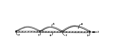
Referring to FIG. 1, a cross section of a portion of an absorbent article
according to a
preferred embodiment of the present invention is shown. Against the body of
the wearer is a
bodyside liner or topsheet 1 superposed on a multifunctional transfer layer 2.
Below the
transfer layer (remote from the body side) is an absorbent core 3 superposed
on a liquid
impervious backsheet 4. The present invention is primarily concerned with the
novel
properties of the multifunctional transfer layer 2, one embodiment of which is
depicted in
more detail in FIG. 2. An expansion layer 5 is attached to a stability layer 6
by discrete or
heterogeneous attachment means 7, here depicted as spaced apart deposits of
adhesive
material. The expansion layer material 5 expands in the lateral direction
parallel to the cross-
sectional length shown in FIG. 2. As illustrated in FIG. 3, upon wetting the
expansion of the
expansion layer 5 results in puckering due to restraint by the stability layer
6 through the
heterogeneous attachment means 7, yielding elevated pockets 8 which can hold
fluid and
conduct fluid in a preferred direction, while increasing the elevation of the
topsheet to
maintain better fit against the body. In addition to flow channels and void
volume created by
the formation of the pockets 8, the narrow dimensions about the contact points
7 provides a
- 12-
CA 02284809 1999-09-23
WO 98/47455 PCT/US98/06175
region having a small capillary diameter suitable for wicking fluid along the
length of the
pocket 8, especially if hydrophobic glue or other non-hydrophobic attachment
means are
used. A three-dimensional view of an expanded, puckered expansion layer 5 on a
stability
layer 6 is shown in FIG. 4, where several of the multiple elongated pockets 8
are identified.
Similarly, FIG. 8 illustrates an absorbent structure having two expansion
layers oriented
orthogonally, although the relative orientation of the two expansion layers
can be from about
5 or 10 degrees to 90 degrees out of alignment.
The expanded structure in FIG. 4 could be created by attaching the stability
layer to
the expansion layer with parallel lines of adhesive to yield parallel,
continuous pucker pockets
upon wetting of the expansion layer. However, in terms of the structure and
layout of
attachment means such as adhesive, many other embodiments are possible and
within the
scope of invention. Continuous elongated pucker pockets may be created with
pleasing or
more functional shapes by, for example, depositing adhesive between the
expansion layer
and stability layer in patterns that are sinusoidal, saw toothed, etc., as
depicted in FIG. 5, or
the attachment means may be applied in the form of spaced apart, patterned
dots or dashes
andlor fines or other geometric forms, with two examples depicted in FIG. 6.
Diamond
patterns or rhombic arrays of dots and lines are envisioned as potentially
useful structures.
Lines of adhesive on the sides of the transfer layer may also be useful to
prevent flow and
wicking in the cross direction of the article (the direction normal to the
primary longitudinal
axis of the article), thus reducing the likelihood of leaking, especially in
feminine pads and
similar articles.
Though the expansion layer 5 can comprise any wettable material which expands
laterally when wetted, the creped tissue webs are preferred for their low cost
and ease of
manufacture. Exemplary methods of creping tissue on a Yankee or drum dryer are
disclosed
in US Pat. No. 5,494,554, "Method for Making Soft Layered Tissues," issued
Feb. 27, 1996 to
Edwards et al.; US Pat. No. 4,064,213, "Creping Process Using Two-position
Adhesive
Application," issued Dec. 20, 1977 to Lazorisak et al.; US Pat. No. 4,533,437,
"Papermaking
Machine," issued Aug. 6, 1985 to Curran and Kershaw; and US Pat. No.
3,879,257, issued
April 22, 1975 to Gentile et al.; all of which are hereby incorporated by
reference. Creping can
be executed in many ways known to those skilled in the art. In addition to
creping on a
Yankee dryer, creping of a previously dried web, or "dry creping," can be
done, including the
method of jamming paper into a throat of two constricting plates, as
originally described by E.
Heuser in three articles in Papier Zeiteuy, 35(94): 3559-3560 (Nov. 24, 1910);
35(99): 3743
- 13-
CA 02284809 1999-09-23
WO 98/47455 PCTIUS98/06175
(Dec. 11, 1910) and 36(8):251-253 (Jan. 26, 1911 ). A related technique is the
dry
microcompression or microcreping operation on a web as it is physically jammed
against a
solid surface, as disclosed in US Pat. No. 4,919,877, "Process for Softening
Webs," issued to
M. N. Parsons and R. L. Abba, April 24, 1990, hereby incorporated by
reference. Other
methods for foreshortening or laterally microcompressing a dry or partially
dried web are
given in US Pat. No. 2,624,245, issued to Cluett, hereby incorporated by
reference; US Pat.
No. 3,290,209 issued to Ihrman, also hereby incorporated by reference, and US
Pat. No.
4,469,735, issued to Trokhan. It is important that creping or foreshortening
of the web be
done after the sheet is substantially dry (over 50% dryness, preferably over
80%, and more
preferably over 90% dryness). In this manner, the sheet can expand laterally
when wetted
because many or most of the hydrogen bonds between fibers were formed in a
relatively flat
state, to which the creped sheet will seek to return when fibers are wetted
and fiber stresses
relax.
Most preferred are creped tissue webs comprising wet strength agents to
produce a
wet:dry machine direction tensile strength ratio of at least 0.1, preferably
at least 0.2, more
preferably at least about 0.3, and most preferably at least about 0.5. The
crepe ratio should
be high enough to permit significant expansion of the web upon wetting, such
that the degree
of expansion in the machine direction is at least 10%, preferably at least
20%, more
preferably at least 30%, more preferably still at least about 50%, and most
preferably from
about 8% to about 100%. High wet strength and wet resiliency improves the
ability to produce
stable, elevated "pucker pockets" upon wetting with urine, menses, or other
aqueous fluids.
Without wishing to be bound by theory, the physics of the invention can be
illustrated
by considering the physical changes that occur in a dry creped tissue when it
is wetted. A dry
creped tissue is typically formed by draining an aqueous slurry of papermaking
fibers on a
forming fabric and progressively dewatering the embryonic web and then
pressing the wet
web onto a heated Yankee dryer. The combination of conductive heat transfer
from the
steam-filled Yankee and convective heat transfer from the impingement of hot
air in the
Yankee hood leads to substantial drying of the flat, dense web that has been
pressed and
adhered to the Yankee surtace. In dry creped tissue production, the sheet
dryness typically
exceeds 80% before the sheet is removed from the Yankee. At this dryness
level, many
hydrogen bonds form between adjoining cellulose surfaces as water is removed,
and the
hydrogen bonding establishes the strength and "inherent topography" of the
web. Further,
typical wet strength resins become cured during this drying stage in a flat
state. Since the
- 14-
CA 02284809 1999-09-23
WO 98/47455 PCT/US98J06175
bonds between fibers are formed while the fibers lie flat, the inherent
topography is that of a
flat sheet. Removal of the web from the Yankee is accomplished by the scraping
action of a
creping doctor blade which imparts numerous fine wrinkles and folds in the
tissue structure
and breaks a portion of the hydrogen bonds between fibers, resulting in a
bulkier, softer
product with some free fibers and high mechanical stretch. The creped sheet
has a new
topography with many fine peaks and valleys defined by the kinks and folds
imparted to the
dry fibers by creping. The creped topography is not defined by fiber-fiber
bonds, but rather by
deformations imparted to the dry fibers after bonding has been substantially
accomplished.
When the creped sheet is subsequently wetted, the fibers swell as they imbibe
water.
During swelling, many of the local stresses in the web from kinks and folds
are relaxed. The
swollen fibers allow the creped structure to be relaxed, meaning that the
fibers have a
tendency to straighten out during swelling and to return to the "inherent
topography" defined
by the fiber-fiber bonds. Thus, the wetted creped sheet seeks to return to its
flat state. To do
so, the sheet must expand in the machine direction. If the creped sheet is
restrained in
certain regions, then expansion of the web between the regions of restraint
can cause
buckling, in which the sheet deforms out of the plane. Simple geometry can be
used to
predict the increased height of the surface due to expansion of the web into
puckered
regions. Significant elevation gains are possible. For example, if a creped
tissue web is
anchored to a stability layer with adhesive zones spaced 5 mm apart, and the
web has a
degree of expansion of 30%, upon wetting the initially flat web could pucker
in an
approximately arcuate shape having a height gain of 1.75 mm. 9
The manner of estimating the possible rise of an expansion layer upon wetting
can be
illustrated with respect to FIG. 7. A section of a stability layer 6 is
connected to a section of an
expansion layer 5 at two points by adhesive 7. Initially, the dry expansion
layer and stability
Payer are coplanar and have a length of 2L between the adhesive spots 7. After
wetting, the
section of the expansion layer expands from its dry length 2L to a new arc
length of S, which
is a section of a circle having radius R. The arc S is subtended by the angle
2A, and the
midpoint of the arc, where the arc is raised from the plane of stability layer
by a height of Dy,
is subtended by the angle 0. The degree of expansion of the expansion layer is
(S-2L)12L.
Given S and L, 0y can be computed by solving the following equations:
S = 20 R
- 15-
CA 02284809 1999-09-23
WO 98/47455 PCT/L1S98/06175
6 = sip '(L./f?) (2)
(3)
Equations 1 and 2 can be combined to solve for R given L and S, followed by
use of
Equation 3 to yield dy, or, in numerically easier approach, R and L can be
specified, then S, 0
and Dy can be found directly with Equations 1 to 3, followed by calculation of
the degree of
expansion, (S-2L)/2L. For example, Table 1 below shows the results for several
choices of R
and L:
R (mm) L (mm) dY (mm) Theta (rad). S (mm) Deg. Exp.
2 1.8 1.13 1.12 4.48 0.244
3 2.8 1.92 1.20 7.22 0.290
5 - 4.9 4.01 1.37 13.70 0.398
9 5.64 1.12 22.40 0.244
13 7.52 1.05 31.45 0.210
Table 1. Calculations for vertical rise of a simple expansion layer for
choices of R and L.
10 For expansion layers with a modest degree of expansion (about 0.2 to about
0.4),
significant calculated vertical rise values (dy} can be obtained. Of course,
their are several
simplifications that may affect the results. The shape of the pocket may not
be spherical, but
can depend on details of the restraining means at the contact points 7. If the
span (2L) is too
great, the pocket formed by expansion of a #hin web may lack adequate
stiffness to support
15 itself under modera#e toad or capillary forces, and the pocket may collapse
and form multiple
smaller wrinkles. The stiffness, wet strength, and basis weight of the
expansion layer will
determine the optimum spacing of contact points on the stability layer to
achieve maximum
vertical rise, if maximum rise is sought. In practice, it is believed that
best results may be
obtained with contact points spaced apart by about 2 to 20 mm, preferably
about 3 to 15 mm,
and most preferably about 4 to 10 mm.
Though the expansion layer is preferably flat and thin in the dry state, it
can be
provided with texture. For example, the sheet or web of the expansion layer
may be
embossed, lightly pleated or creased, crinkled, apertured, cut, perforated,
slit, and the like.
Perforation, slitting and needling may be desired in some cases to increase
fluid flow through
the multifunctional transfer layer.
- 16-
CA 02284809 1999-09-23
WO 98/47455 PCT/US98/06175
The stability layer can be a tissue or paper material, or can be composed of
plastics,
nonwoven fibrous webs, fibrous composites, laminates, apertured films, and the
like. The
stability layer should be as stiff or stiffer than the expansion layer so that
it does not deform
excessively in the primary direction of the expansion layer when wetted.
Preferably, the basis
weight of the stability layer is at least 20 gsm, more preferably at least 30
gsm, and most
preferably between 25 and 80 gsm. Embodiments include the stability layer as a
through-
dried tissue web, as a fluff pulp pad with sufficient strength and resilience
to serve effectively
in a multifunctionat transfer layer, or as a polyolefin fibrous material of
sufficient basis weight
and strength to stabilize the expanding expansion layer.
The attachment means or restraining means connecting the expansion layer to
the
stability layer can include any adhesive means known in the art, including but
not limited to
thermofusible glues, such as those comprising adhesive resin, a polymer and a
wax, wherein
said thermofusible glue is applied as hot filaments deposited onto the
expansion layer or
stability layer, or by spraying; other thermoplastic wax-containing compounds;
cold glues,
such as acrylic or vinyl glues in emulsion or solution form in a solvent,
wherein the glue is
sprayed, coated, poured, or printed onto the surface of either the expansion
layer or stability
layer; starches; latexes, especially hydrophilic latexes; extruded polymer
threads, filaments,
or webs that are placed in contact with a web and then bonded by melting onto
the web.
Hydrophilic glues are particularly desirable, including those disclosed by T.
Chihani and A.
Silfverstrand in Great Britain Patent Application GB 2,294,397-A, "Hydrophilic
Gfue for
Bonding Absorbent Article," published June 1, 1996. Such glues include
dispersion glues and
hot melts modified to be hydrophilic by grafting hydrophilic moieties onto an
othewise
hydrophobic polymer oc by adding surfactants to an otherwise hydrophobic
composition. A
hot melt glue based on a grafted polymer may include 70-90 percent by weight
of,a graft
copolymer and 10 to 30 percent by weight of an adhesive agent such as a
natural or
synthetic resin. The graft copolymer comprises a vinyl monomer such as vinyl
acetate or an
alkyl substitute acrylate and a water soluble polyalkene oxide such as ethene
oxide, propene
oxide, or mixtures thereof. Hot melts made hydrophobic with addition of
surfactants may be
based on a thermoplastic elastomer or an atactic poly-a-olefin, as atactic
polypropylene. The
surfactant is preferably non-ionic and may be an alcohol, an alkanolamide, an
amino oxide,
an ester, or an ether. Hydrophilic starch-based hot melts may include a
modified starch ester
such as starch propionate and starch acetate. Organic solvents may be useful
when added to
the starch composition to provide improved hot melt properties. The solvent
may be a
- 17-
CA 02284809 1999-09-23
WO 98/47455 PCTI(1598/06175
sulfonamide, a carboxylic acid, a carboxylic acid ester, an amide, a phosphate
ester, an
alcohol or an ester. Preferably, the solvent will be a sulfonamide, an
alcohol, an amide, or an
ester. Combinations of hydrophobic and hydrophilic glues may be used to
provide regions of
high wettability and barrier regions which inhibit wicking, particular near
the edges of an
article where hydrophobic glue or resin may be useful in limiting transport,
while hydrophilic
glues in the center of the article may help improve fluid intake, transport,
and absorbency.
The attachment means can also be substantially mechanical, as exemplified by
needling of two layers to entangle them together; by crimping or embossing or
pert
embossing to adjoin plies or layers; by sewing, etc. Other attachment means
include
ultrasonic bonding, wherein a thermoplastic material in the stability layer or
an added hot glue
between the two Payer is fused by ultrasonic energy. Frictional engagement can
also be used
without adhesive means, especially when a textured, uncreped, wet resilient
web is used as
the stability layer. Preferably, the three-dimensional tissue serving as the
stability layer is
urged against the expansion layer by physical forces such as compressive force
from the
body of the user, tension from a topsheet or tension in either the stability
layer or expansion
layer, or other means for biasing the stability layer toward the expansion
layer to permit
frictional engagement.
The bodyside liner or topsheet may comprise materials known in the art,
including
apertured films; nonwoven webs such as spunbond, meltblown, or bonded carded
webs;
spunlaced or hydroentangted webs; creped or uncreped tissues, including soft
uncreped
through-air dried webs such as those disclosed by Farrington et al., US Pat.
No. 5,607,551,
previously incorporated by reference; and the like. The topsheet may be
apertured, slit,
embossed, perforated, and the like, and may be treated with softening agents,
surfactants for
improved hydrophilicity, hydrophobic matter and fibers for improved dry feel,
as disclosed in
the aforementioned copending application of Chen et al. entitled "Dual-Zoned
Absorbent
Webs", emollients, bactericides and fungicides, and the like, for improved
performance,
health, and comfort. In one embodiment, the topsheet comprises a bonded carded
web
(BCW) which has a basis weight in the range of about 10-40 gsm and is composed
of fibers
having a fiber denier within the range of about 1.0-3.0 dpf. In some
embodiments, the
topsheet also serves as the stability layer, wherein the expansion layer is
deposed below the
topsheet. However, this is normally not preferred because of the high
stiffness that is
desirable in the stability layer, which stiffness may result in discomfort
against the skin. In a
- 18-
CA 02284809 1999-09-23
WO 98/47455 PCT/US98/06175
separate embodiment, the expansion layer also serves as the topsheet, with a
stability layer
being below the expansion layer.
The absorbent core can be a unitary or multilayered material comprising
cellulosic
andlor non-cellulosic materials, including but not limited to fluff pulp,
creped tissue layers,
uncreped tissue layers, superabsorbents, cotton linters, peat moss, vegetable
matter,
nonwoven webs of polymeric fibers, woven materials, and composites of any of
the
foregoing. The core may be embossed, textured, cut, slit, compressed, coated,
or treated in
any manner known in the art. Chemical additives may be incorporated into the
structure,
including bactericides, odor-control agents, perfumes, and the like.
Additional layers may be incorporated into the absorbent article, including
additional
transfer layers composed of substantially hydrophobic materials, optionally
treated with a
surfactant or otherwise processed to import a desired level of wettability and
hydrophilicity,
and composites, such as those disclosed in US Pat. No. 5,389,202, "Process for
Making a
High Pulp Content Nonwoven Composite Fabric," issued Feb. 14, 1995 to C. H.
Everhart et
al., hereby incorporated by reference. Low-basis weight surge layers may be
incorporated in
diapers or related articles, with examples of potentially usef::l structures
disclosed in US Pat.
No. 5,364,382, "Absorbent Structure Having Improved Fluid Surge Management and
Product
Incorporating Same," issued Nov. 15, 1994 to t_atimer et al., and US Pat. No.
5,429,629,
"Absorbent Structure Having Improved Fluid Surge Management and Product
Incorporating
Same," issued July 4, 1995 to Latimer et al., both or which are hereby
incorporated by
reference. Care must be taken that the other components of the absorbent
article do not
interfere with the desired functions of the multifunctional transfer layer.
Other components
may also be included in the absorbent article, including fastening means,
tabs, elastic
threads, inserts, adhesive bands or straps, etc.
The liquid impervious backsheet 4 can be any material known in the art. In the
various
embodiments of the invention, the backsheet 4 can be composed of a
substantially liquid
impermeable material, and is typically manufactured from a thin plastic film,
or other flexible
liquid-impermeable material. However, polymer-wood fiber composites may also
be used, or
even tissue-based structures with suitable imperviousness to liquid. As used
in the present
specification, the term "flexible" refers to materials which are compliant and
which will readily
conform to the general shape and contours of the wearer's body. Backsheet 4
prevents the
exudates contained in the absorbent article from wetting articles such as
bedsheets and
overgarments which contact the article. For example, backsheet 4 can be a
polyethylene film
- 19-
CA 02284809 1999-09-23
WO 98/47455 PCT/US98/06175
having a thickness of from about 0.012 millimeters (0.5 mil) to 0.051
millimeters (2.0 mils).
Depending upon cost constraints and strength requirements, a typical
polyethylene film has a
thickness of about 1 mil. Alternative constructions of the backsheet may
comprise a woven or
nonwoven fibrous web layer which has been constructed or treated to impart the
desired level
of liquid impermeability. For example, the backsheet may comprise a polymer
film, such as
polyethylene film available from Edison Plastics, a business having offices
located in South
Plainfield, N.J. The polymer film backsheet can also be embossed andlor matte
finished to
provide a more aesthetically pleasing appearance. Backsheet 4 may optionally
be composed
of a vapor permeable, "breathable" material which permits vapors to escape
from the
absorbent structure while still substantially preventing liquid exudates from
passing through
the backsheet. For example, backsheet 4 can comprise a microporous, polymer
film, or a
nonwoven fabric which has been coated or otherwise treated to impart desired
levels and
combinations of liquid impermeability and vapor permeability. The shape and
size of the
backsheet are determined by the size and contour of the absorbent article and
by the
particular design selected. When used in a diaper or similar article, for
example, the
backsheet may have a generally T-shape, a generally I-shape or a modified
hourglass shape,
and may extend beyond the terminal edges of the article by a selected
distance, e.g., 1.3
centimeters to 2.5 centimeters (0. 5 to 1.0 inch).
The multifunctional transfer layer 2 and backsheet 4 are connected or
otherwise
associated together in an operable manner. As used therein, the term
"associated"
encompasses configurations where multifunctional transfer layer 2 is directly
joined to
backsheet 4 by affixing marginal areas of multifunctional transfer layer 2
directly to backsheet
4, and configurations where multifunctional transfer layer 2 is joined to
backsheet 4 by
affixing multifunctional transfer layer 2 to intermediate members which in
turn are affixed to
backsheet 4. Multifunctional transfer layer 2 and backsheet 4 can be affixed
directly to each
other in the periphery of the article by periphery attachment means such as an
adhesive,
sonic bonds, thermal bonds or any other attachment means known in the art. For
example, a
uniform continuous layer of adhesive, a patterned layer of adhesive, or an
array of separate
lines, swirls or spots of construction adhesive may be used to affix
multifunctional transfer
layer 2 to backsheet 4 in a manner to retain the absorbent core 3 in position.
It is readily
apparent that the above-described attachment means may also be employed to
interconnect
and assemble together the other component parts of the article.
- 20-
CA 02284809 1999-09-23
WO 98147455 PCT/US98/06175
The absorbent structures of the present invention are described herein in
relationship
to their use in disposable absorbent articles, but it should be understood
that potential uses of
the absorbent structures of the present invention need not be limited to
disposable absorbent
articles. As used herein, the term "disposable absorbent article" refers to
articles which
absorb and contain body exudates and are intended to be discarded after a
limited period of
use. They are not intended to be laundered or otherwise restored for reuse.
The articles can
be placed against or in proximity to the body of the wearer to absorb and
contain various
exudates discharged from the body, including but not limited to urine, menses,
sweat, blood,
wound exudates, saliva, mucous, and feces. In addition, absorbent articles for
removal of
other fluids are envisioned, such as advanced paper towels to remove liquids
from hands;
industrial wipers; oil absorbent materials for industrial and home use;
absorbent articles for
removal of chemical spills; absorbent pads for packaging of meats, poultry,
and vegetables to
remove fluids; and the like.
Diapers incorporating the present invention may be constructed according to
any of
the many methods known in the art, exemplified by US Pat. No. 5,192,606,
"Absorbent Article
Having a Liner Which Exhibits Improved Softness and Dryness, and Provides for
Rapid
Uptake of Liquid," issued Mar. 9, 1993 to Deborah L. Proxmire, et al., hereby
incorporated by
reference.
Feminine pads and incontinence pads may be constructed according to any of the
many methods known in the art, exemplified by US Pat. No. 5,219,341, "Sanitary
Napkin with
a Faster Transverse Wicking Absorbent Layer to Indicate the Approach of
Maximum Fluid
Capacity," issued Jun. 15, 1993 to Serbiak et al.; US Pat. No. 5,248,309,
"Thin Sanitary
Napkin Having a Central Absorbent Zone and a Method of Forming the Napkin,"
issued Sept.
28, 1993 to Serbiak et al.; US Pat. No. 5,545,156, "Absorbent Article Having a
Preforrned
Member," issued Aug. 13, 1996, to J. DiPalma and S. Anjurall; US Pat. No.
5,591,147,
"Absorbent Article Having an Oppositely Biased Attachment Flap," issued Jan.
?, 1997 to L.
Couture-Dorschner et al.; all of which are hereby incorporated by reference.
Additional
constructions for absorbent article are disclosed in US Pat. No. 5,415,640,
"Bodyside Cover
for an Absorbent Article," issued May 16, 1995, to Kirby et al., hereby
incorporated by
reference.
Superabsorbent materials in the form of particles, fibers, films, and coatings
on wood
pulp fibers may be incorporated by any means known in the art into any desired
component
of the structure, including the absorbent core and the multifunctional
transfer layer. Useful
- 21-
CA 02284809 1999-09-23
WO 98/47455 PCT/US98/06175
methods for incorporating superabsorbent particles are disclosed in US Pat.
No. 5,425,725,
"Absorbent Article Which Includes Superabsorbent Material and Hydrophilic
Fibers~Located in
Discrete Pockets," issued June 20, 1995 to Tanzer et al.; and US Pat. No.
5,149,335,
"Absorbent Structure," issued Sept. 22, 1992 to Kellenberger, et al., both of
which are hereby
incorporated by reference. In a preferred embodiment of the present invention,
superabsorbent particles are incorporated between the stability layer and
expansion layer.
The superabsorbent particles are held in place by the two layers, restricted
in motion by the
contact regions where the two layers are joined. When wetted, the space
between the two
layers expands into pucker pockets which also provide ample space for the
superabsorbent
particles to expand. Laminates with superabsorbent particles between tissue
layers are
known in the art, but they have suffered several drawbacks. If the tissue
layers are tightly
connected, the swelling of the superabsorbent particles can break through the
tissue and
release particles from the absorbent article. If the tissue layers have
adequate space
between them to allow the superabsorbent particles to expand, then the
particles will be loose
and may shift or be lost. The present embodiment holds the particles tightly
in the dry state,
but expands in the wet state to allow the superabsorbent particles to absorb
and expand
without damage to the absorbent article or loss in performance.
Alternative configurations of absorbent articles comprising the
multifunctional transfer
layer of the present invention are also envisioned. For example, the expansion
layer of the
multifunctional transfer layer may also serve as a topsheet, in which case the
expansion layer
should comprise soft~and absorbent materials for a soft feel. Multilayered
webs with wet
resilient fibers and wet strength agents in a lower layer and debonded
hardwood fibers in an
upper layer may be useful in such configurations, wherein the lower layer
provides the
strength and much of the expansion required for an effective multifunctional
transfer layer,
while the upper layer provides softness suitable for contact against skin.
Alternatively, the
multifunctional transfer layer may have adequate fluid holding capacity that
no additional
absorbent core is needed, in which case the multifunctional transfer layer
could also serve as
an absorbent core. In that case, incorporation of superabsorbent particles
into the structure
may be desirable, and use of multiple webs in the expansion layer may also be
desirable to
provide higher bulk and fluid capacity. It is also possible for the
multifunctional transfer layer
to replace or incorporate a backsheet, in which case the stability layer would
function also a
backsheet. In one embodiment, that of an improved paper towel or wiper, the
article
comprises a multifunctional transfer layer and a topsheet superposed on the
expansion layer
- 22-
CA 02284809 1999-09-23
WO 98/47455 PCT/US98/06175
to provide improved softness or fluid intake abilities, with no additional
liquid impervious
backsheet required.
Example 1
Creped basesheets for use in the present invention were produced on a pilot
tissue
machine having a web width of 21 inches, trimmed to 17 inches on the reel, and
operating at
approximately 60 feet per minute (fpm) in the wet end. An aqueous slurry of
bleached
chemithermomechanical softwood pulp (BCTMP) made from spruce (Tembec 525/80,
produced by Tembec Corp. of Temiscaming, Quebec, Canada) was pulped at about
4%
consistency. Kymene 557LX (Hercules, Wilmington, DE) wet strength agent was
added at a
dose of about 23 pounds per ton of dry fiber. The slurry was diluted to about
0.5%
consistency and pumped by a fan pump operating at 30 gpm. The slurry was
deposited on a
fine forming fabric, an Appleton Wire 94M fabric. After dewatering by foils
and vacuum boxes,
the wet web was transferred to a felt (Duramesh by Albany International)and
pressed with a
pressure roll at about 35% solids with a pressure of about 30 psi onto the
surface of a heated
Yankee cylinder filled with steam at 26 psi and having a nominal temperature
of 234°F. The
Yankee dryer speed was 60 fpm. The dried sheet was then creped with a doctor
blade at a
10° angle to create about a 17% crepe in the sheet (machine speed on
the wet end is about
17% faster than the speed of the web as it is reeled). Sheets were prepared
with a basis
weight of about 25 gsm (grams per square meter). The thickness of two webs was
0.44 mm.
The basis weight on the Yankee was 22 gsm and 25 gsm on the reel. The web
displayed a
MD degree of expansion of about 10 or 11%. The thickness of a stack of 4 20-
gsm webs at
0.05 psi load under a 3-in diameter platen is 0.91 mm. The average Frazier
porosity was
measured at 165 cfmlftz, MD tensile was 1356 g/3-inches, MD stretch was 17.7%,
CD tensile
was 1073 gl3-inch strip, CD Wet Tensile was 526 g/3-inches, for a CD wet:dry
tensile ratio of
49%. Geometric mean tensile strength (dry state) was 1205 g/3-inches.
The sheets were then converted into single-ply expansion layers by adhering
the
sheets to sections of contact adhesive paper in which the protective non-tacky
release sheet
of the contact paper was cut off and removed in thin, parallel strips about 3
mm wide and
spaced apart to give about 4 mm space between the neighboring sides of
adjacent exposed
adhesive regions of the contact paper. The contact paper so cut and exposed
offered
discrete adhesive strips for restraining the creped web in separate regions.
The creped webs
were then placed in contact with the contact paper such that the machine
direction of the web
- 23-
CA 02284809 1999-09-23
WO 98/47455 PCT/US98/06175
was normal to the longitudinal axis of the exposed strips of adhesive. The
structure was
substantially flat in the dry state.
Upon wetting, the composites of tissue and contact paper developed a three-
dimensional geometry as the tissue expansion layer puckered in the pockets
between the
exposed contact adhesive. The puckers rose to about 2 mm height relative to
the basesheet
and were remarkably uniform in shape. The puckered regions had significant
void volume.
The measured Expansion Height was about 1.3 mm.
As used, the contact paper serving as the stability layer would be undesirable
in most
embodiments of an absorbent article because it is impermeable. However, an
impermeable
contact layer such as the contact paper or other films, sheets, or webs can be
made
permeable by slitting, cutting or punching holes to provide open area.
Preferably, the open
area would be at least 30%, more preferably at least 60%, and most preferably
from about
50% to about 90%.
Example 2
The 20-gsm web of Example 1 was adhered to a non-expandable plastic stability
layer
by means of threads which had been manually wound with double sided tape, the
excess
tape being cut away, to provide adhesive threads. The adhesive threads were
spaced on the
stability layer, a flat plastic film, in parallel lines about 0.25-in apart
and about 4-in in length.
The 20-gsm creped BCTMP tissue web was then adhered on the adhesive threads
with the
machine direction of the tissue web being normal to the direction of the
threads. When
wetted, the expansion of the creped tissue resulted in regular pockets arising
from the dry
plane of the creped tissue (the expansion layer). The pockets contributed both
void volume
and directionality to the composite material, allowing water to wick
effectively in the direction
of the pockets, which is in the cross direction of the web. After drying, the
Expansion Height
of the structure was measured at about 1.5 mm.
Example 3
5-inch squares of the 20-gsm web of Example 1 were combined together to make a
two-ply laminate structure. The adhesive means was 3M Pressure Sensitive
Adhesive 72
(3M, St. Paul, MN) . The adhesive was applied heterogeneously onto the tissue
web by
spraying through an overlaid stencil comprising a punched and cut Mylar sheet
to give 0.25-
inch spots spaced about 1 inch apart, or, alternatively, linear strips of
adhesive about 0.3
- 24-
CA 02284809 1999-09-23
WO 98/47455 PCT/US98/06175
inches wide and spaced apart about 1 inch. After one square of the tissue web
was treated
with adhesive, a similar square was placed onto the treated square and the two
were pressed
together in the adhesivefy treated regions such that the machine directions of
the two
attached squares were substantially orthogonal to each other. When wetted with
tap water,
each layer sought to expand in its machine direction but was restrained by the
other web,
forcing each layer to pucker. The resulting puckering in each sheet was
approximately at right
angles to the puckering of the other sheet, making meshing of the puckered
regions
impossible. One laminate bonded with spaced apart 0.25-inch dots of adhesive
gave an
Expansion Height of 1.71 mm, while other similar samples comprising a mixture
of lines and
spots of the spray adhesive gave Expansion Heights of 1.89, 1.60 mm, and 1.87
mm. A two-
ply laminate about 5-inches square with adhesive bonds on the corner regions
only for
restraint gave an Expansion Height of 1.62 mm.
Example 4
Multi-ply structures with the basesheet of Example 1 were constructed to
further
examine the effect of relative orientation in the sheets. Several two-ply
structures were
prepared and placed together with the machine directions aligned. When wetted,
the sheet
puckered together, meaning that the puckers on the lower sheet were
essentially the same in
shape and size and were in continuous contact with the puckers of the upper
surface, as if
the two sheets had behaved as one. The single-ply web was fully wetted with
deionized water
while under restraint from two long weights spaced about 3-inches apart and
cunning in the
machine direction. The web was wetted while on a flat surface and dried
without restraint.
The Expansion Height of the single-ply web was 0.34 mm (0.56 mm thickness
minus the
initial thickness of 0.22 mm). The Expansion Height of the two-ply sheet was
0.53 mm. A
portion of the same tissue sheet was wetted without restraint and allowed to
dry. The
Expansion Height was only 0.10 mm. Without restraint, the sheet can expand
across the full
machine-direction width of the web, resulting in fewer wrinkles.
Example 5
The creped basesheet of Example 1 was placed underneath a three-dimensional,
uncreped through-dried tissue structure to provide largely frictional
restraint of the creped
web upon wetting.
- 25-
CA 02284809 1999-09-23
WO 98147455 PCT/US98/06175
The uncreped web was made according to the procedures disclosed in copending
U.S. application Serial Number 081614,420 by Chen et al. entitled "Wet
Resilient Webs and
Disposable Articles Made Therewith", previously incorporated by reference. The
basesheet
was produced on a continuous pilot scale tissue machine adapted for uncreped
through-air
drying comprising a Fourdrinier forming section, a transfer section, a through-
drying section,
a subsequent transfer section and a reel. A dilute aqueous slurry at
approximately 1%
consistency was prepared from 100% spruce bleached chemithermomechanical pulp
(BCTMP), pulped for 20 minutes at about 4% consistency prior to dilution. The
spruce
BCTMP is commercially available as Tembec 525180, produced by Tembec Corp. of
Temiscaming, Quebec, Canada. Kymene 557LX wet strength agent, manufactured by
Hercules, Inc., Wilmington, Delaware, was added to the aqueous scurry at a
dosage of about
pounds of Kymene per ton of dry fiber. The slurry was then deposited on a fne
forming
fabric and dewatered by vacuum boxes to form a web with a consistency of about
~ 2%. Said
web was then transferred to a transfer fabric (Lindsay Wire 952-505) using a
vacuum shoe at
15 a first transfer point with a slight speed differential between the two
fabrics. The web was
further transferred from the transfer fabric to a woven through-drying fabric
at a second
transfer point using a second vacuum shoe. The through drying fabric used was
a Lindsay
Wire T-116-3 design (Lindsay Wire Division, Appleton Mills, Appleton,
Wisconsin), based on
the teachings of U.S. Patent No. 5,429,686 issued to Kai F. Chiu et al, hereby
incorporated
20 by reference. The T-116-3 fabric is well suited for creating molded, three-
dimensional
structures. The web was then passed over a hooded through-dryer where the
sheet was
dried. The hood temperature was approximately 300°F. The dried sheet
was then transferred
from the through-drying fabric to another fabric, from which the sheet was
reeled. Sheets
produced in this manner have a Dry Bulk of about 10 to 20 cc/g and can have a
typical
Surface Depth on the fabric side of the web of about 0.3 mm to 0.8 mm or
greater.
The through-dried web placed on top of a single ply of the otherwise
unrestrained
creped tissue web and water was poured onto the uncreped web to wet both it
and the
underlying creped tissue. The wetted creped tissue produced a series of long,
regularly
spaced puckers apparently defned by the long surface channels of the high bulk
uncreped
through-air dried material. The BCTMP creped web had an Expansion Height of
1.70 mm.
Another sample prepared with similar procedures gave an Expansion Height of
0.73 and 0.96
mm, as measured in two different portions of the web.
- 26-
CA 02284809 1999-09-23
WO 98/47455 PCT/US98/06175
The multifunctional transfer layers of the above examples could be
incorporated into a
diaper, preferably comprising an additional soft topsheet on the bodyside and
superposed on
a multifunctional transfer layer, a breathable clothlike backsheet, and a low
caliper absorbent
core comprising fluff pulp and superabsorbent particles placed between said
backsheet and
said multifunctional transfer layer. Additionally, the multifunctional
transfer layers of the above
examples could be incorporated into a high performance laminated towel
comprising one or
more of said multifunctional transfer layers arranged in a stack with at least
one exterior
surface of said stack further attached to a soft, creped or uncreped tissue
web, selected for
its absorbency and softness rather than for its wet expansion. Since BCTMP and
other high-
yield fibers desirable for the present invention are typically not white, the
outer layer may be
selected for a bright white color as well, comprising bleached papermaking
fbers such as
bleached kraft eucalyptus. Known creped materials and existing towel products
could be
improved in performance by attaching one or more of said multifunctional
transfer layers
underneath one Layer or between two layers of known creped materials and prior
art paper
towels. Upon wetting, the internal void volume of the laminated towel would
increase
considerably, allowing for improved performance, less liquid strike through or
penetration to
the skin of the user, and better cleaning due to the textured interior layer
or layers.
Example 6
At a commercial tissue mill, a creped tissue sheet was produced from a slurry
of
100% spruce BCTMP with the added wet strength resin being AMRES 8870 from
Georgia
Pacific at a dosage of about 7.5 kilograms per metric ton of fiber. The
diluted slurry was
formed on a Fourdrinier with a pressure former and then the wet web was
pressed onto a hot
Yankee dryer with an air impingement hood and creped to give a tissue
basesheet having a
basis weight of 30.8 grams per square meter. The creped web had a wet:dry
tensile strength
ratio of 35%, a geometric mean tensile strength of 1006 gramsl3 inches, an MD
tensile
stretch of 19.9%, a CD stretch of 2.5%, a caliper (using an EMVECO thickness
gauge which
applies a pressure of 0.289 psi over a 2.22-inch diameter foot) of 10.7 mils,
a density of 0.113
g/cc, an MD:CD tensile strength ratio of 0.88; and a Frazier porosity of 74
cubic feet/ftz-min.
The tissue web was conditioned in a Tappi room and cut to 3-inch diameter
disks.
Stacks were formed from 10 plies of the tissue sheet. One set of stacks,
hereafter Set A, had
the machine direction of each layer in the stack aligned in the same
direction. In the other set
of stacks, hereafter Set B, each layer was positioned such that the machine
direction was
- z7-
CA 02284809 1999-09-23
WO 98/47455 PCT/L1S98/06175
normal (at a 90-degree angle) to the sheets adjacent to it (above and below).
Stacks from Set
A and Set B were then wetted in two different ways. In one series of trials,
the stacks were
wetted by pouring a stream of deionized, room-temperature water during a
period of about 10
seconds around the edges of the stacks while they were resting horizontally on
a table,
without any compressive load being applied to the stacks during wetting.
Wicking of the water
quickly resulted in complete wetting of the stack. This treatment will be
designated as "no-
load wetting." Stack thickness was measured under the 0.2 psi toad before and
after wetting.
(After thickness measurement in the dry state, the platen of the thickness
measurement
device, hereafter described, was raised so the stack was no longer under a
compressive
load.) Thickness of the stacks was measured in a thickness measurement device
wherein the
stack is placed on a flat marble surface and under a brass platen 3-inches in
diameter that is
connected through a flexible linkage to a Mitutoyo digital thickness gauge,
such that the total
pressure applied to the sample by the platen and by the measurement spindle of
the
thickness gauge was 0.2 psi. For absorbent articles, a load of 0.2 psi is
considered fairly high
compared to normal compressive loads and represents a relatively severe test
of an article's
resistance to compression. After wetting for the no-load wetting condition,
the thickness of the
stack was measured. There was a total lapse of approximately 30 seconds
between the
beginning of wetting and thickness measurement of the stack.
In another set of runs, the brass platen, while connected to the thickness
gauge, was
first placed on the dry stack of 10 layers of tissue to completely cover it
and to permit dry
thickness to be measured. Then a squirt bottle was used to apply deionized
water to the
exposed outer perimeter of the tissue stack to thoroughly wet it, with wicking
bringing water to
the inner portions of the stack while under load, allowing the thickness to be
read after
wetting. The process of wetting and wicking required about 30 seconds before
the thickness
measurement was recorded. This process will be designated as "wetting under
load." The
combination of two types of stacks, Set A and Set B, and two means of wetting
and
measuring of thickness, no-load wetting and wetting under load, results in 4
experimental
conditions. For each condition, three replicates were run. Thickness results
at 0.2 psi are
shown in Table 2. Table 3 reports bulk values based on the average thickness
results in
Table 2.
- 28-
CA 02284809 1999-09-23
WO 98/47455 PCT/US98/06175
Samples No-load wetting Wetted under
~ load
Dry Wet Dry Wet
thickness, thickness, thickness, thickness,
in in in in
Set A 0.087 0.085 0.087 0.074
(aligned)
Set A 0.088 0.075 0.091 - 0.078
(aligned)
Set A 0.090 0.065 0.091 0.078
(aligned)
Set A 0.088 0.075 0.090 0.077
Average:
Set B 0.089 0.150 0.093 0.093
(aftema6ng)
Set B 0.089 0.174 0.093 0.093
(aftema6ng)
Set B 0.087 0.158 0.089 0.091
(aftemating)
Set B 0.088 0.161 0.092 0.092
Average:
Table 2. Thickness of dry and wetted stacks of creped tissue.
Samples No-load wetting ~ ~ Wetted
under load
Set A 7.23 6.17 7.40 6.33
Bulk:
Set B 7.23 13.24 7.56 7.56
Bulk:
Table 3. Bulk values (cclg) at 0.2 psi based on average thicknesses from Table
2.
- 29-
CA 02284809 1999-09-23
WO 98/47455 PCT/US98/06175
Without wishing to be bound by theory, observations of stack behavior when wet
appear to be consistent with basic principles. When aligned stacks of tissue
sheets (Set A)
are wetted under no load, the relaxation of crepe folds results in a machine-
direction
elongation of the stack and some puckering. As a result of the elongation of
the stack, the
effective basis weight and thickness of the web decrease. Under load, less
elongation may
occur. When non-aligned stacks of tissue sheets (Set B) are wetted under no
load, machine
direction expansion of any one layer is restrained in part by the adjoining
tissue layers having
their machine directions turned at a 90° angle. As a result, more
puckering occurs and
relatively little in-plane expansion is expected.
The thickness results for no-toad wetting of Set B show.that the alternating
layers can
gain and maintain significant bulk when wetted, going from an average stack
thickness of
0.088 inches dry to 0.161 inches when wet. The crisscross puckering of the
alternating layers
provides this increase in bulk, even when the wetted stack is exposed to a
fairly severe
compressive load of 0.2 psi. When the layers are aligned with a common
orientation for the
machine direction, as is the case for Set A, the puckering that does occur is
not enough to
overcome the decreased thickness due to elongation and possibly decreased
elastic modulus
of the wetted fibers (causing increased z-direction compression of the web)
and thus, the
wetted stack has a reduced thickness of 0.075 inches compared to 0.088 inches
dry. When
the stacks are wetted under load, it is believed that there is less
opportunity for puckering to
occur because the load provides a vertical restraint over the entire surface
of each layer.
Nevertheless, Set B still outperforms Set A when wetted under load. In Set B,
enough
puckering still occurs in spite of the compressive Toad during wetting to
overcome any
decrease in stack thickness due to the slight elongation of the tissue layers
or the reduced
elastic modulus of the fibers, maintaining a thickness of 0.092 inches. In Set
A, however, the
stack loses bulk, compressing from 0.090 inches dry to 0.077 inches when wet.
The bulk values show that a stack of alternating creped tissue layers can
maintain an
effective bulk of about 13 cclg or greater under a load of 0.2 psi when wetted
under no load,
or a bulk of about 7.5 or greater when wetted under a load of 0.2 psi.
Multiple layers of expanding material such as creped tissue should be arranged
such
that the direction of expansion is not aligned for all layers. The multiple
layers may be held in
place with respect to each other by adhesive, by external restraining forces
or pressure, by
sewn thread, and other means known in the art. Such stacks of expanding webs
could serve
- 30-
CA 02284809 1999-09-23
WO 98/47455 PCT/LTS98/06175
effectively as napkins, as absorbent media for toxic spills, as absorbent
cores in diapers or
meat pads or other absorbent articles, etc.
The foregoing examples serve to illustrate possible approaches pertaining to
the
present invention in which improved fluid handling, void volume, and surface
elevation for
improved fit are achieved through the novel constructions herein disclosed.
However, it will
be appreciated that the foregoing examples, given for purposes of
illustration, are not to be
considered as limiting the scope of this invention which is defined by the
following claims and
all equivalents thereto.
- 31-