Note: Descriptions are shown in the official language in which they were submitted.
CA 02284855 2000-08-17
-1-
A RAIL MOUNTED PATIENT LIFT
The present invention relates to an a rail mounted patient lift.
It is known to displace rail mounted patient lifts along a rail to a desired
location to attach and lift a patient and then move the patient by the lift.
This is
normally done by a hand-held controller device which an attendant operates to
displace the lift carriage from a stored position, usually at an end of the
rail and move
it along the rail to a desired position. When doing so, the attendant will
follow the
carriage along the rail, with the controller in hand, to a position where a
patient is
then fitted with a harness to be attached to a sling hanger of the lift. The
attendant
then lowers the sling using the hand-held controller. Because these carriages
are
displaced at relatively slow speeds along the rail, it is time-consuming to
retrieve the
carriage from a stored position and move it to a desired position.
As is well known, in present day health care systems, the cost of operating
the health care systems is of great concern. Therefore, if the time required
to displace
these lifts was to be greatly reduced, this would permit the attendant,
usually a
5 nurse's aide, to carry out other functions instead of walking by the lift as
it is
displaced from its stored position to a position of use and back to the
storage position.
In other words, if the lift could be automatically displaced from a stored
position to a desired position of use and effect other functions on its own
safely, this
10 would permit the nurse's aide to do other jobs such as the placement of a
sling around
the patient while the lift is being displaced to a position above the patient.
CA 02284855 2001-O1-08
-2-
According to one aspect of the present invention, there is provided a
rail mounted patient lift comprising a ceiling mounted rail, a carriage
mounted
for displacement along said rail, power operated drive means for displacing
the carriage along the rail, a sling hanger secured to a flexible elongate
support
element, power operated lifting means for extending and retracting the
elongate support element relative to the carriage, a manually operable
controller and control circuit means for moving said carnage to a selected one
of a plurality of different positions along the rail in response to a first
command signal from the controller. A load detector is provided for detecting
if a load is present on the sling hanger. The power operated lifting means is
operable by the control circuit means to raise the sling hanger, if in a down
position with no load thereon, when receiving a command signal from the
controller to move the carnage along the rail.
According to another aspect of the invention there is provided a rail
mounted patient lift comprising a ceiling-mounted rail, a carriage mounted for
displacement along said rail, motorised drive means for displacing said
carriage, a sling hanger secured to a retractable cable and vertically
displaceable from said carnage by a lift motor, control circuit means for
receiving command signals from a hand-operated controller, a load detector to
detect if a load is present on said sling hanger, said control circuit
operating
said lift motor to retract said sling hanger if in a down position with no
load
thereon when receiving a command signal from said control circuit to freely
move said carriage on said rail from a homing position, said control circuit
having a programmable memory with a homing function to automatically
return said carriage to said homing position when receiving a homing signal,
and means to arrest said freely moving carriage at a desired position along
CA 02284855 2000-08-17
-3-
said rail.
A preferred embodiment of the present invention will now be described, by
way of example, with reference to the accompanying drawings, in which:
FIG. 1 is a perspective view showing a rail mounted patient lift
incorporating therein one embodiment of an automatic displacement and homing
system, according to the present invention;
FIG. 2 is a schematic illustration showing a configuration of a ceiling-
mounted rail supported from a ceiling in a room and having a predetermined
number
of position identification magnetic elements secured thereto;
FIG. 3 is an exploded view showing the construction of the carriage and
the various elements associated therewith; and
FIG. 4 is a block diagram of the control circuit and its associated circuitry.
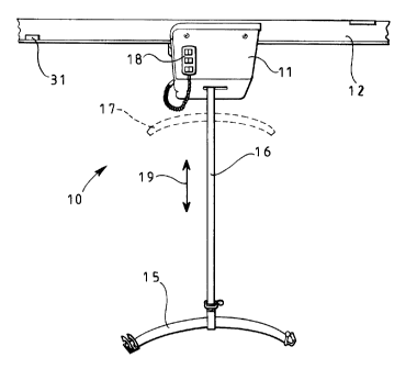
Referring now to the drawings and more particularly to Figure 1, there is
shown generally at 10 a rail mounted patient lift. It comprises a carriage 11
which is
displaceably secured to a ceiling mounted rail 12. As shown in Figure 2, the
rail 12
is configured to position the patient lift 10 at various locations or
positions therealong,
5 such as beds, bathing positions, etc., and these positions are identified
herein by
reference numerals 13, 13', 13" and 13"'. The carriage 11 is usually stored at
a
CA 02284855 2000-08-17
-4-
storage or homing position 14 or 14' which is usually at the end of the rail
12.
As shown in Figure 1, a sling hanger 15 is suspended from a cable or strap
16 and movable vertically from a down position of use, as shown in Figure 1,
to a
retracted stored position 17 as identified in phantom lines. A hand-operated
controller
18, which may be carriage-mounted or remote, connects to an internal control
circuit
mounted on the carriage support frame and controls the displacement of the
carriage
11 along the rail 12 and the displacement of the sling hanger 15 in an up-and-
down
direction as identified by arrow 19 whereby the user can attach the sling
hanger 15
to a sling supporting a patient to raise the patient or lower the patient and
displace
him along the rail 12 to a desired location.
Referring now to Figure 3, there is shown a typical construction of the
patient lift and as hereinshown it comprises a carriage 11 having of a frame
20 which
supports a drive motor 21 which operates a drive wheel 22 through a belt drive
23.
The drive wheel 22 is engaged with the rail 12 and displaces the carriage
therealong.
5 An idle guide wheel 24 is spaced from the drive wheel and guides the
carriage
through curves and provides the proper spaced support for the frame 20. A lift
motor
25 drives a belt sheave 26 about which the belt or cable 16 is wound to move
the sling
hanger 15 up and down from the carriage. The lift motor is sufficiently strong
to
handle heavy weight patients. An electronic control circuit 27 having a
programmable
10~ memory 28 is provided on a chipboard 29 and housed at an appropriate
location on
the frame 20. Battery supplies 30 provide the proper voltage for the operation
of the
motor and the control circuit. However, the supply may also be provided
through an
CA 02284855 2000-08-17
-5-
AC supply cable but the DC supply version is usually preferred. Other various
component parts of the carriage are herein illustrated but will not be
described as they
do not form part of the present invention.
As shown in Figure 3, a position detector 31' is secured at a convenient
location inside the carriage and adjacent the lower edge of the track 12 to
detect the
presence of switching identifying means, herein constituted by one or more
magnetic
elements 31 which are secured adjacent the lower edge of the rail 12 to
identify the
various locations 13 to 13"' or work stations. These elements are simply small
magnetic pieces which are adhesively attached to the rail and which are easy
to
remove to change the desired positions 13 to 13"'. When the position detector
31',
e.g. a Hall effect device, senses the magnet 31 as the carriage approaches it,
it sends
a signal to the control circuit 27 which then effectuates a function with
respect to the
programmed memory circuit 28.
As shown in Figure 4, a load or weight detector 32 is associated with the
cable sheave 26 of the sling hanger 15 and detects the presence of a load on
the sling
hanger. The control circuit 27 operates the lift motor 25 to retract the sling
hanger
when in a down position with no load thereon when receiving a command signal
5 from the control circuit to freely move the carriage in a forward direction
on the rail
from the homing position 14. The control circuit programmable memory has a
homing function to also automatically return the carriage when receiving a
homing
signal from the hand-operated controller 18.
CA 02284855 2000-08-17
-6-
As shown in Figure 4, the hand-operated controller 18 has a first switch 33
for actuating the lift motor to raise the sling hanger 15 and a second switch
34 to
actuate the lift motor to lower the sling hanger 15. As long as the switches
33 and 34
are depressed, the motor operates. When the switches are released, the motor
will
stop. The controller 18 is also provided with a station identification switch
35. If the
rail is provided with four stations and the operator wishes the carriage to
displace
itself to the third station, he will depress the switch 35 three times. This
will program
the memory 28 to cause the control circuit to operate the drive motor 21 past
the first
and second positions 13 and 13' . As the carriage passes positions 13 and 13'
, it will
emit an audible signal through the signal generator device 36 identifying that
the
carriage is in movement and has passed the first and second stations and is on
its way
to the third station. Upon reaching the third station the program memory will
cause
the control circuit to stop the drive motor 21. It is also conceivable that
the controller
may have a keypad with numbered stations so that by depressing a certain key
the
desired station will be identified and the control circuit, through its
memory, will
operate in the same manner to position the carriage adjacent that desired
station.
The controller 18 is also provided with a homing switch 37 where upon
being depressed the control circuit will lift the sling hanger 15 if there is
no weight
on it and once lifted will move the carriage 11 to its homing position, either
position
14 or 14' . The program memory could also be programmed for each of the homing
5 ~ positions and this could be done by depressing switch 37 once for position
14 and
twice for position 14', or again it could consist of a keypad which would
identify the
homing positions by individualized keys. Switches 38 and 39 indicate to the
control
CA 02284855 2000-08-17
_7_
circuit in which direction the carriage is to be moved along the rail, either
in a
forward direction or a rearward direction and the control circuit will operate
the drive
motor either clockwise or counter-clockwise. Although the hand-operated
controller
18 is herein shown as being secured to the carriage 11, as previously
mentioned, it
could also be a remote controller and operate in a manner well known in the
art.
Another function in the program memory is that once the carriage
automatically displaces itself and arrives at the desired location, once
arriving at the
location, it will automatically operate the lift motor 25 to automatically
lower the
sling hanger 15 by dispensing a predetermined cable length. This predetermined
cable
5 length could be fixed so that the sling hanger is arrested at a desired
height from the
floor surface. It can therefore be appreciated that all the attendant needs to
do to
displace the patient lift from its homing position to a desired position is to
actuate the
switch 35 and the carriage will start displacing itself without the attendant.
In the
meantime, the attendant can go to the desired location and place a harness
around the
patient while the carriage is slowly moving along the track. As the carriage
passes by
stations positioned forward of the desired location, it will send an audible
signal
informing the attendant, herein a nurse's aide, that it is on its way. By the
time the
attendant has prepared the patient, the carriage arrives and the sling hanger
is
automatically lowered. The patient is attached to the sling hanger and the
attendant
uses the hand operated controller 18 to retract the cable to move the patient
to a
desired height and then actuates the switches 38 or 39 to displace the
carriage along
the rail to another position where the patient is either lowered in a bath, a
wheelchair,
a bed, etc. The attendant can then depress switch 37 and the sling hanger will
be
~
CA 02284855 2000-08-17
_g_
automatically retracted and the carriage will move back to its homing position
and
during this time of travel the attendant can also carry out other functions.
It is within the ambit of the present invention to cover any obvious
modifications of the preferred embodiment of the present invention as
described
herein. For example, the predetermined locations 13 to 13" may be identified
by
programming the memory to monitor the operation of the drive motor and by
doing
so predetermined positions may be identified by the distances travelled by the
carriage
along the rail.