Note: Descriptions are shown in the official language in which they were submitted.
CA 02284856 1999-09-24
WO 98/43578 PCT/US97/05046
1
ABSORBENT ARTICLE HAVING IMPROVED FLUID ACQUISITION PERFORMANCE
Field of the invention
The present invention relates to absorbent articles which are primarily
designed to receive and retain bodily discharges such as - and foremost -
urine.
Such articles are disposable hygiene articles like baby diapers, training
pants,
Adult Incontinence Articles and the like.
Background of the invention
Absorbent Articles for receiving and retaining bodily discharges such as urine
or faeces such as disposable diapers, training pants, adult incontinence
articles
are well known in the art, and significant effort has been spent against
improving
their performance. Such improvements generally aim at addressing the primary
function of such articles, namely retaining body fluids, but also at
minimising the
negatives associated with wearing such articles by increasing the comfort of
the
wearer.
Such improvements can mostly be classified to primarily fall within either of
two categories: primarily relating to "core technology", i.e. "absorbency" in
the
broad sense of the word, or primarily relating to "chassis technology".
CA 02284856 1999-09-24
WO 98/43578 PCT/US97/05046
2
The first addresses how to pick up and retain the body waste (generally in
some state of fluidity) in an "absorbent (or core) structure", whereby the
waste
material is acquired by the article (picked up) and then stored (retained),
with
potentially an additional step of distribution (in particular of urine) in
between.
The second category deals - generally - with the so called "chassis
elements", namely containing the body waste "within the confinement of the
article"
- by separating the absorbent (core structure) and the outside, i.e. wearers
garments, etc., by using an impermeable "backsheet";
- or by preventing bodily exudates from escaping through the space between
the absorbent article and the body of the wearer, such as by elasticised
gatherings at leg and waist openings.
This also deals with enabling application of the article to the wearer - such
as
by providing closure means such as tapes, and maintaining the article on the
wearer, such as through belt like arrangements often integrated into the
application means.
With this terminology, "comfort" for the wearer is at present predominantly
being addressed by improving chassis elements, such as by adopting the
chassis elements of the diaper to provide good "fit" of the article and to be
soft
and cushioning.
In PCT application WO 93/'16669 (Alemany) or PCT application WO
93121877 (Richardson) disposable diapers are described, whereby the comfort of
the wearer is enhanced by introducing elasticised features such as allowing
better body conformity even if the wearer is moving.
When considering the impact of cores on comfort, the general approach is to
do so by using soft, non chafing materials for topsheets or minimising the
thickness andlor volume of the dry article, preferably whilst maintaining
softness
i
CA 02284856 2002-12-02
3
of such cores. Recently, attempts have been made to also adopt the form and
shape of the absorbent structure to allow good fit.
Since so called superabsorbent materials (or hydrogel forming
materials) have found wide spread application in disposable absorbent
articles, a number of marketed products - such as PAMPERST"" as sold by
The Procter & Gamble Co. or HUGGIEST"" as sold by Kimberly-Clark Corp. in
various countries - underwent a remarkable reduction in the thickness of the
products.
US-A-5,098,423 (Pieniak) describes disposable diapers, which attempts to
address various "comfort" aspects by providing "low dry bulk" structures,
claiming that not only the dry thickness of the structure is relevant, but
also
other dimensions like
- the cross-sectional area of the core in the crotch region;
- the compressibility of the article in the crotch region and the resulting
thickness of the article after folding;
- size of the "impact zone of the article";
- distance of the (leg) elastic members of the article.
Hence, the core structures described herein can be called thin, but wide.
Further, an "Absorbency Efficiency Index" is described, by relating an
amount of fluid, which should be picked up by the crotch region, to the volume
of the dry core. The objective of this parameter is to allow designing towards
high absorbency characteristics, capacity, in the crotch region. Thus is still
a
key objective to also absorb large amounts of urine in the crotch area, which,
however, inevitably reduces comfort after loading significantly. This issue
becomes even more pronounced with further improving the performance of
absorbent articles yielding absorbent articles providing significantly better
fluid
handling performance, and hence an increase in overall wearing time and
amount of fluid contained in such articles before being removed.
In (US-A-4,994,037 (Bernardin) absorbent articles are described,
having a "reversed capacity profile". Therein, the ultimate storage capacity
is
positioned
i ; ~ ~,
CA 02284856 2002-12-02
4
away from the crotch region. However, the disclosed designs for absorbent
articles do not consider the fit requirement of fitting well between the legs
of
the wearer, nor the fluid handling requirements, such as achieving appropriate
skin dryness and fluid acquisition. Whilst these designs arrange the capacity
away from the loading point, they were not concerned with how to effectively
achieve the fluid transport to these storage regions.
Hence it is an object of an aspect of the present invention to provide
absorbent articles having an improved fit also when being loaded, together
with good fluid handling performance, especially having a good acquisition
performance.
It is a further object of an aspect of the present invention to achieve this
by
selectively placing ultimate storage capacity away from the crotch region.
It is a further object of an aspect of the present invention to provide this
feature without detrimentally affecting the fit when dry by providing designs
with low bulk in the article crotch region.
It is a further object of an aspect of the invention to achieve this by using
distribution materials having high flux wicking properties.
It is a further object of an aspect of the invention to achieve this by using
Superabsorbent polymers.
It is a further object of an aspect of the invention, to achieve this by using
porous absorbent materials, such as made by HIPE polymerisation.
According to an aspect of the present invention, there is provided an
absorbent article comprising an absorbent core comprising a crotch region
and one or more waist regions, whereby said crotch region has a lower
ultimate fluid storage capability than said one or more waist region together,
and wherein said article has an Acquisition performance of at least 0.5 ml/sec
for the fourth gush.
i
CA 02284856 2002-12-02
4a
According to another aspect of the present invention, there is provided an
absorbent article comprising an absorbent core comprising a crotch region
and one or more waist regions, whereby said crotch region has a lower
ultimate fluid storage capability than said one or more waist regions
together,
and wherein the article has an Acquisition Performance of at least 3.75 ml/sec
for the first gush.
Figure 1 is schematically showing a baby diaper as an example for an
absorbent article.
Figure 2 is schematically showing a Pull up baby diaper as an example for
an absorbent article.
CA 02284856 1999-09-24
WO 98!43578 PCT/US97/05046
Figure 3 is showing the test set up for the Vertical Wicking Test.
Figure 4 is showing the test set up for the Acquisition Test.
Figure 5 is showing the test set up for the Post Acquisition Collagen Rewet
Method. _
Detailed Description
Absorbent Articles - general
As used herein, the term "absorbent articles" refers to devices which absorb
and contain body exudates, and, more specifically, refers to devices which are
placed against or in proximity to the body of the wearer to absorb and contain
the
various exudates discharged from the body, primarily urine.
The term "disposable" is used herein to describe absorbent articles which are
not intended to be laundered or otherwise restored or reused as an absorbent
article (i.e., they are intended to be discarded after use and, preferably, to
be
recycled, composted or otherwise disposed of in an environmentally compatible
manner).
An absorbent article generally comprises:
- an absorbent core or core structure (which may consist of sub- structures);
- a fluid pervious topsheet;
- a fluid impervious backsheet;
- optionally further features tike closure elements or elastification.
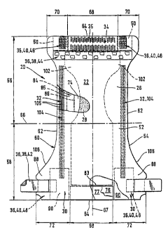
Figure 1 is a plan view of an embodiment of an absorbent article of the
invention which is a diaper.
The diaper 20 is shown in Figure 1 in its flat-out, uncontracted state (i.e.
with
elastic induced contraction pulled out except in the side panels wherein the
CA 02284856 1999-09-24
WO 98/43578 PCT/US97105046
6
elastic is left in its relaxed condition) with portions of the structure being
cut-away
to more clearly show the construction of the diaper 20 and with the portion of
the
diaper 20 which faces away from the wearer, the outer surface 52, facing the
viewer. As shown in Figure 1, the diaper 20 comprises a containment assembly
22 preferably comprising a liquid pervious topsheet 24, a liquid imperrrious
backsheet 26 joined with the topsheet 24, and an absorbent core 28 positioned
between the topsheet 24 and the backsheet 26; elasticised side panels 30;
elasticised leg cuffs 32; an elastic waist feature 34; and a closure system
comprising a dual tension fastening system generally multiply designated as
36.
The dual tension fastening system 36 preferably comprises a primary fastening
system 38 and a waist closure system 40. The primary fastening system 38
preferably comprises a pair of securement members 42 and a landing member
44. The waist closure system 40 is shown in Figure 1 to preferably comprise a
pair of first attachment components 46 and a second attachment component 48.
The diaper 20 also preferably comprises a positioning patch 50 located
subjacent
each first attachment component 46.
The diaper 20 is shown in Figure 1 to have an outer surface 52 (facing the
viewer in Figure 1 ), an inner surface 54 opposed to the outer surface 52, a
first
waist region 56, a second waist region 58 opposed to the first waist region
56,
and a periphery 60 which is defined by the outer edges of the diaper 20 in
which
the longitudinal edges are designated 62 and the end edges are designated 64.
The inner surface 54 of the diaper 20 comprises that portion of the diaper 20
which is positioned adjacent to the wearer's body during use (i.e. the inner
surface 54 generally is formed by at feast a portion of the topsheet 24 and
other
components joined to the topsheet 24). The outer surface 52 comprises that
portion of the diaper 20 which is positioned away from the wearer's body (i.e.
the
outer surface 52 generally is formed by at least a portion of the backsheet 26
and other components joined to the backsheet 26). The first waist region 56
and
the second waist region 58 extend, respectively, from the end edges 64 of the
periphery 60 to the lateral centreline 66 of the diaper 20. The waist regions
each
comprise a central region 68 and a pair of side panels which typically
comprise
the outer lateral portions of the waist regions. The side panels positioned in
the
first waist region 56 are designated 70 while the side panels in the second
waist
region 58 are designated 72. While it is not necessary that the pairs of side
CA 02284856 1999-09-24
WO 98143578 PCT/US97105046
7
panels or each side panel be identical, they are preferably mirror images one
of
the other. The side panels 72 positioned in the second waist region 58 can be
elasticaNy extensible in the lateral direction (i.e. elasticised side panels
30). (The
lateral direction (x direction or width) is defined as the direction parallel
to the
lateral centreline 66 of the diaper 20; the longitudinal direction (y
direction or
length) being defined as the direction parallel to the longitudinal centreline
67~
and the axial direction (Z direction or thickness) being defined as the
direction
extending through the thickness of the diaper 20).
Figure 1 shows a specific of the diaper 20 in which the topsheet 24 and the
backsheet 26 have length and width dimensions generally larger than those of
the absorbent core 28. The topsheet 24 and the backsheet 26 extend beyond
the edges of the absorbent core 28 to thereby form the periphery 60 of the
diaper
20. The periphery 60 defines the outer perimeter or, in other words, the edges
of
the diaper 20. The periphery 60 comprises the longitudinal edges 62 and the
end
edges 64.
The containment assembly 22 of the diaper 20 is shown in Figure 1 as
comprising the main body (chassis) of the diaper 20. The containment assembly
22 comprises at least an absorbent core 28 and preferably an outer covering
layer comprising the topsheet 24 and the backsheet 26. When the absorbent
article comprises a separate holder and a liner, the containment assembly 22
generally comprises the holder and the liner (i.e. the containment assembly 22
comprises one or more layers of material to define the holder while the liner
comprises an absorbent composite such as a topsheet, a backsheet, and an
absorbent core). For unitary absorbent articles, the containment assembly 22
comprises the main structure of the diaper with other features added to form
the
composite diaper structure. Thus, the containment assembly 22 for the diaper
20
generally comprises the topsheet 24, the backsheet 26, and the absorbent core
28.
While each elasticised leg cuff 32 may be configured so as to be similar to
any of the leg bands, side flaps, barrier cuffs, or elastic cuffs described
above, it
is preferred that each elasticised leg cuff 32 comprise at least an inner
barrier
cuff 84 comprising a barrier flap 85 and a spacing elastic member 86 such as
~ i~.;ii, ~',
CA 02284856 2002-12-02
8
described in US Patent 4,909,803. In a preferred embodiment, the elasticised
leg cuff 32 additionally comprises an elastic gasketing cuff 104 with one or
more elastic strands 105, positioned outboard of the barrier cuff 84 such as
described in US Patent 4,695,278.
The diaper 20 may further comprise an elastic waist feature 34 that
provides improved fit and containment. The elastic waist feature 34 at least
extends longitudinally outwardly from at least one of the waist edges 83 of
the
absorbent core 28 in at least the central region 68 and generally forms at
least
a portion of the end edge 64 of the diaper 20. Thus, the elastic waist feature
34 comprises that portion of the diaper at least extending from the waist edge
83 of the absorbent core 28 to the end edge 64 of the draper 20 and is
intended to be placed adjacent the wearer's waist. Disposable diapers are
generally constructed so as to have two elastic waist features, one positioned
in the first waist region and one positioned in the second waist region. While
a
disposable diaper of the present invention can be constructed with a single
elastic waist feature encircling the wearer or having a bolstering waist
feature
with rear elastics only, the discussion regarding the elastic waist feature
will
focus on diapers having a pair of elastic waist features, at least one, and
preferably both, being constructed according to the present invention.
Further,
while the elastic waist feature or any of its constituent elements can
comprise
a separate element affixed to the containment assembly 22 of the diaper 20,
the elastic waist feature 34 will be described with respect to a preferred
embodiment in which the elastic waist feature 34 is constructed as an
extension of other elements of the diaper such as the backsheet 26 or the
topsheet 24, preferably both the backsheet 26 and the topsheet 24.
The elasticised waist band 35 of the elastic waist feature 34 may comprise
a portion of the topsheet 24, a portion of the backsheet 26 that has
preferably
been mechanically stretched and a bi-laminate material comprising an
elastomeric member 76 positioned between the topsheet 24 and backsheet
26 and resilient member 77 positioned between backsheet 26 and elastomeric
member 76.
CA 02284856 2002-12-02
9
This as well as other components of the diaper are given in more detail in
WO 93/16669.
Figure 2 shows a further example for an absorbent article for which the
present invention may be applied, namely a disposable pull-up diaper. The
disposable pull-up diaper 20 comprise a chassis 21, side seems 23, and an
absorbent assembly 22. The chassis 21 will have at least a front portion 56, a
rear portion 58, a crotch portion 57, longitudinal side regions 88, and ear
flaps
72 and will comprise an elastic ear flap member 90 operatively associated with
each ear flap 72 to form a laminated ear flap which will be elastically
activated
by a mechanical stretching process which will be described in greater detail
herein below. The absorbent assembly 22 is secured to the chassis 21.
The outer layer 26 is that portion of the chassis 21 which ~ will form the
exterior of the disposable pull-up diapers 20, i.e. face away from the wearer.
The outer layer 26 is compliant, soft feeling, and non-irritating to the
wearer's
skin.
The inner layer 24 is that portion of the chassis 21 which will form the
interior of the chassis 21, and will contact at least the waist and legs of
the
wearer. The inner layer is also compliant, soft feeling, and on-irritating to
the
wearer's skin.
The inner layer 24 is preferably positioned adjacent to the outer layer 26
and is preferably joined thereto by attachment means (not shown) such as
those well known in the art. For example, the inner layer 24 may be secured to
the outer layer 26 by a uniform continuous layer of adhesive, a patterned
layer
of adhesive, or an array of separate lines, spirals, or spots of adhesive.
According to an embodiment of the invention, the inner layer 24 and the
outer layer 26 are indirectly joined together by directly joining them to the
elastic ear flap members 90, elastic waste band members 76, and elastic
strands 105 and are joined directly to each other in the areas extending
beyond
the elastic ear flap member 90, elastic waste band members 76, and elastic
strands 45.
In a preferred embodiment, at least a portion of the chassis inner and outer
layers 24, 26 will be subjected to mechanical stretching in order to provide a
CA 02284856 1999-09-24
WO 98/43578 PCT/US97/05046
"zero strain" stretch laminate that forms the elasticised ear flaps 30. Thus,
the
inner and outer layers 24, 26 are preferably elongatable, most preferably
drawable, but not necessarily elastomeric, so that the inner and outer layers
24,
26 will, upon mechanical stretching, be at least to a degree permanently
elongated such that they will not fully return to their original undistorted
configuration. In preferred embodiments, the inner and outer layers 24, 26 can
be subjected to mechanical stretching without undue rupturing or tearing.
Thus, it
is preferred that the inner and outer layers 24, 26 have a low cross-machine
direction (lateral direction) yield strength.
The chassis 21 of the disposable pull-up diapers 20 preferably further
comprises elasticised leg cuffs 32 for providing improved containment of
liquids
and other body exudates. Each elasticised leg cuff 32 may comprise several
different embodiments for reducing the leakage of body exudates in the leg
regions. While each elasticised leg cuff 32 may be configured so as to be
similar
to any of the leg bands, side flaps, barrier cuffs, or elastic cuffs described
above,
it is preferred that each elasticised leg cuff 32 comprise at least a side
flap 104
and one or more elastic strands 105.
The chassis 21 of the disposable pull-up diapers 20 further preferably
comprises an elasticised waistband 34 disposed adjacent the end edge 64 of the
disposable pull-up diapers 20 in at least the rear portion 58, and more
preferably
has an elasticised waistband 34 disposed in both the front portion 56 and the
rear portion 58. The waistband of the disposable pull-up diapers 20 is that
portion which is intended to be placed adjacent the wearer's waist. The
elasticised waistband 34 provides a member that maintains a defined area
coverage, contacts the wearer's waist, and is elastically extensible in at
least the
lateral direction so as to dynamically fit against the waist of the wearer and
to
dynamically conform to the waist of the wearer so as to provide improved fit.
Thus, the waistband is generally that portion of the disposable pull-up
diapers 20
extending from the end edge 64 of the disposable pull-up diapers 20 to at
least
the waist edge 83 of the absorbent core 28. While the elasticised waistband 34
can comprise a separate element affixed to the chassis 21 of the disposable
pull-
up diapers 20, the waistband is preferably an extension of other elements of
the
disposable pull-up diapers 20 such as the inner layer 24, the outer layer 26,
or
CA 02284856 1999-09-24
WO 98/43578 PCT/US97/05046
11
any combination of these elements and an elastomeric material joined thereto.
Alternatively, the topsheet and the backsheet of the absorbent assembly 22,
may
extend beyond the edges of the absorbent core 28 and have an elastomeric
material joined thereto to form an elasticised waistband. Disposable training-
pants are often constructed so as to have two elasticised waistbands; one
positioned in the front portion 56 and one positioned in the rear portion 58.
The
disposable pull-up diapers 20 at least has an elasticised waistband 34
disposed
in at least the central region 68 of the rear portion 58. Preferably another
elasticised waistband is disposed on the front portion 56. Preferably both
elasticised waistbands 34 are disposed between the elasticised ear flaps 30.
The elasticised waste band 34 may be constructed in a number of different
configurations. According to figures 2 and 3, the elasticised waste band 34
comprises an elastic waste band member 76 interposed between the inner layer
24 and outer layer 26 and is operatively associated with either or both of the
inner or outer layers 24, 26 together with the front portion 56 and rear
portion 58
of the disposable pull-up diapers 20.
In a preferred embodiment, the chassis 27 comprises elasticised ear flaps 30
in the front portion 56 and the rear portion 58. The elasticised ear flaps 30
are
unitary elements of the chassis, i.e. they are not separately manipulative
elements secured to the chassis, but rather are formed from and are extensions
of the chassis materials. The elasticised ear flaps 30 provide an elastically
extensible feature that provides a more comfortable and contouring fit by
initially
conformably fitting the disposable garment to the wearer and sustaining this
fit
throughout the time of wear well past when the disposable garment has been
loaded with exudates since the elasticised ear flaps allow the sides of the
disposable garment to expand and contract.
Each ear flap 72 comprises that portion of the chassis 21 that extends
laterally outwardly from and along the central region 68 of the chassis 21 to
the
longitudinal side region 88 of the chassis 21. The ear flap 72 generally
extends
longitudinally from the end edge 64 of the chassis 21 to the portions of the
longitudinal edge 62 of the chassis 21 that forms the leg opening (this
segment
of the longitudinal edge 62 being designated as leg edge 106). In a preferred
CA 02284856 1999-09-24
WO 98143578 PCT/US97/05046
12
embodiment of the present invention, each ear flap is formed by the portions
of
the inner layer 24 and the outer layer 26 that extend beyond the central
region
68 of the chassis 21.
In an embodiment of the present invention, the elastic ear flap members 90
are operatively associated with the chassis 21 in the ear flaps 72, preferably
between the inner layer 24 and the outer layer 26, so that the elastic ear
flap
members 90 allow the elasticised ear flaps 30 to be elastically extensible in
the
lateral direction (laterally elastically extensible). As used herein, the term
"elastically extensible" means a segment or portion of the chassis that will
elongate in at least one direction (preferably the lateral direction for the
ear flaps
and the waistbands) when tensional forces (typically lateral tensional forces
for
the ear flaps and the waistbands) are applied, and wiU return to about its
previous size and configuration when the tensional forces are removed.
Generally, elastomeric materials useful in the present invention will
contractiveiy
return to at least about 75% of their original configuration within about 5
seconds
or less upon stretch and immediate release thereof (i.e. a "snappy" elastic).
Absorbent core / core structure
The absorbent core (28) should be generally compressible, conformable,
non-irritating to the wearer's skin, and capable of absorbing and retaining
liquids
such as urine and other certain body exudates. As shown in Figure 1, the
absorbent core 28 has a garment surface ("lower" or "bottom" part), a body
surface, side edges, and waist edges. The absorbent core might comprise a wide
variety of liquid-absorbent or liquid handling materials commonly used in
disposable diapers and other absorbent articles such as - but not limited to
comminuted wood pulp which is generally referred to as airfelt; meltblown
polymers inctuding coform; chemically stiffened, modified or cross-linked
celiulosic fcbres; tissue including tissue wraps and tissue laminates.
Examples for absorbent structures are described in U.S. Patent 4,610,678
entitled "High-Density Absorbent Structures" issued to Weisman et al. on
September 9, 1986; U.S. Patent 4,673,402 entitled "Absorbent Articles Wth
Dual-Layered Cores" issued to Weisman et al. on June 16, 1987; U.S. Patent
CA 02284856 1999-09-24
WO 98/43578 PCT/US97/05046
13
4,888,231 entitled "Absorbent Core Having A Dusting Layer" issued to Angstadt
on December 19, 1989; EP-A-0 640 330 of Bewick-Sonntag et al.; US 5 180 622
{Berg et af.); US 5 102 597 (Roe et al.); US 5 387 207 (LaVon). Such
structures
might be adopted to be compatible with the requirements outline below for
being
used as the absorbent core 28.
The absorbent core 28 can be a unitary core structure, or it can be a
combination of several absorbent structures, which in turn can consist of one
or
more sub-structures. Each of the structures or sub-structures can have an
essentially two-dimensional extension (i.e. be a layer) or a three-dimensional
shape.
Materials for being used in absorbent cores
The absorbent core for the present invention can comprise fibrous materials
to form fibrous web or fibrous matrices.
Fibres useful in the present invention include those that are naturally
occurring fibres (modified or unmodified), as well as synthetically made
fibres.
Examples of suitable unmodifiedlmodified naturally occurring fibres include
cotton, Esparto grass, bagasse, kemp, flax, silk, wool, wood pulp, chemically
modified wood pulp, jute, rayon, ethyl cellulose, and cellulose acetate.
Suitable
synthetic fibres can be made from polyvinyl chloride, polyvinyl fluoride,
polytetrafluoroethylene, polyvinylidene chloride, polyacrylics such as ORLON~,
polyvinyl acetate, polyethylvinyl acetate, non-soluble or soluble polyvinyl
alcohol,
polyolefins such as polyethylene (e.g., PULPEX~) and polypropylene,
polyamides such as nylon, polyesters such as DACRON~ or KODEL~,
polyurethanes, polystyrenes, and the like. The fibres used can comprise solely
naturally occurring fibres, solely synthetic fibres, or any compatible
combination
of naturally occurring and synthetic fibres. The fibres used in the present
invention can be hydrophilic, or can be a combination of both hydrophilic and
hydrophobic fibres.
CA 02284856 1999-09-24
WO 98!43578 PCT/US97/05046
14
For many absorbent cores or core structures according to the present
invention, the use of hydrophilic fibres is preferred. Suitable hydrophilic
fibres for
use in the present invention include cellulosic fibres, modified cellulosic
fibres,
rayon, polyester fibres such as polyethylene terephthalate (e.g., DACRON~),
hydrophilic nylon (HYDROFIL_~}, and the like. Suitable hydrophilic fibres can
also
be obtained by hydrophilizing hydrophobic fibres, such as surfactant-treated
or
silica-treated thermoplastic fibres derived from, for example, polyoiefins
such as
polyethylene or polypropylene, polyacrylics, polyarnides, polystyrenes,
polyurethanes and the like.
Suitable wood pulp fibres can be obtained from well-known chemical
processes such as the Kraft and sulfite processes. It is especially preferred
to
derive these wood pulp fibres from southern soft woods due to their premium
absorbency characteristics. These wood pulp fibres can also be obtained from
mechanical processes, such as ground wood, refiner mechanical,
thermomechanical, chemomechanical, and chemothermo-mechanical pulp
processes. Recycled or secondary wood pulp fibres, as well as bleached and
unbleached wood pulp fibres, can be used.
A desirable source of hydrophilic fibres for use in the present invention,
especially for absorbent regions requiring both good fluid acquisition and
distribution properties, is chemically stiffened celluiosic fibres. As used
herein,
the term "chemically stiffened ceilulosic fibres" means cellulosic fibres that
have
been stiffened by chemical means to increase the stiffness of the fibres under
both dry and aqueous conditions. Such means can include the addition of a
chemical stiffening agent that, for example, coats andlor impregnates the
fibres.
Such means can also include the stiffening of the fibres by altering the
chemical
structure, e.g., by crosslinking polymer chains.
Polymeric stiffening agents that can coat or impregnate the cellulosic fibres
include: cationic modified starches having nitrogen-containing groups (e.g.,
amino groups) such as those available from National Starch and Chemical Corp.,
Bridgewater, NJ, USA; latexes; wet strength resins such as polyamide-
epichlorohydrin resin (e.g., Kymene~ 5~7H, Hercules, Inc. Wilmington,
Delaware, USA}, polyacrylamide resins described, for example, in U.S. Patent
CA 02284856 1999-09-24
WO 98/43578 PCT/US97/05046
3,556,932 (Coscia et al), issued January 19, 1971; commercially available
polyacrylamides marketed by American Cyanamid Co., Stamford, CT, USA,
under the tradename Parez~ 631 NC; urea formaldehyde and melamine
formaldehyde resins, and polyethylenimine resins. A general dissertation on
wet
strength resins utilised in the paper art, and generally applicable herein,
can be
found in TAPPI monograph series No. 29. "Wet Strength in Paper arid
Paperboard", Technical Association of the Pulp and Paper Industry (New York,
1965).
These fibres can also be stiffened by chemical reaction. For example,
crosslinking agents can be applied to the fibres that, subsequent to
application,
are caused to chemically form intrafibre crosslink bonds. These crosslink
bonds
can increase the stiffness of the fibres. While the utilisation of intrafibre
crosslink
bonds to chemically stiffen the fibre is preferred, it is not meant to exclude
other
types of reactions for chemical stiffening of the fibres.
Fibres stiffened by crosslink bonds in individualised form (i.e., the
individualised stiffened fibres, as well as process for their preparation) are
disclosed, for example, in U.S. Patent 3,224,926 (Bernardin), issued December
21, 1965; U.S. Patent 3,440,135 (Chung), issued April 22, 1969; U.S. Patent
3,932,209 (Chatterjee), issued January 13, 1976; and U.S. Patent 4,035,147
(Sangenis et al), issued December 19, 1989; U.S. Patent 4,898,642d (Moore et
al), issued February 6, 1990; and U.S. Patent 5,137,537 (Herron et al), issued
August 11, 1992.
In currently preferred stiffened fibres, chemical processing includes
intrafibre
crosslinking with crosslinking agents while such fibres are in a relatively
dehydrated, defibrated (i.e., individualised), twisted, curled condition.
Suitable
chemical stiffening agents are typically monomeric crosslinking agents
including,
especially C2-Cg polycarboxylic acids such as citric acid.
Such stiffened fibres that are twisted and curled can be quantified by
referencing both a fibre "twisted count" and a fibre "curl factor". As used
herein;
the term "twist count" refers to the number of twist nodes present in a
certain
length of fibre. Twist count is utilised as a means of measuring the degree to
CA 02284856 1999-09-24
WO 98/43578 PCTIUS97/05046
16
which a fibre is rotated about its longitudinal axis. The term "twist node"
refers to
a substantially axial rotation of 180° about the longitudinal axis of
the fibre,
wherein a portion of the fibre (i.e., the "node") appears dark relative to the
rest of
the fibre when viewed under a microscope with transmitted light. The twist
node
appears dark at locations wherein the transmitted light passes through an
additional fibre wall due to the aforementioned rotation. The distance between
nodes corresponds to an axial rotation of 180°. The number of twist
nodes in a
certain length of fibres (i.e., the twist count) is directly indicative of the
degree of
fibre twist, which is a physical parameter of the fibre. The procedures for
determining twist nodes and total twist count are described in U.S. Patent
4,898,642.
Such stiffened fibres will further have an average dry fibre twist count of at
least about 2.7, preferably at least about 4.5 twist, nodes per millimetre.
Furthermore, the average wet fibre twist count of these fibres should
preferable
be at least about 1.8, preferably at least about 3.0, and should also
preferably be
at least about 0.5 twist nodes per millimetre less than the average dry fibre
twist
count. Even more preferably, the average dry fibre twist count should be at
least
about 5.5 twist nodes per millimetre, and the average wet fibre twist count
should be at least about 4.0 twist nodes per millimetre and should also be at
least 1.0 twist nodes per millimetre less than its average dry fibre twist
count.
Most preferably, the average dry fibre twist count should be at least about
6.5
twist nodes per millimetre, and the average wet fibre twist count should be at
least about 5.0 twist nodes per millimetre and should also be at least 1.0
twist
nodes per millimetre less than the average dry fibre twist count.
In addition to being twisted, these preferred stiffened fibres are also
curled.
Fibre curl can be described as the fractional shortening of the fibre due to
kinks,
twists, andlor bends in the fibre. For the purposes of the present invention,
fibre
curl is measured in terms of a two dimensional plane. The extent of fibre
curling
can be quantified by referencing a fibre curl factor. The fibre curl factor, a
two
dimensional measurement of curl, is determined by viewing the fibre in a two
dimensional plane. To determine curl factor, the projected length of the fibre
as
the longest dimension of a two dimensional rectangle encompassing the fibre,
~.~~._..."_.~.._~.w...~.~.. r l , ..
CA 02284856 1999-09-24
WO 98/43578 PCT/US97/05046
17
LR, and the actual length of the fibre, LA, are both measured. The fibre curl
factor can then be calculated from the following equation:
Curl Factor = (LA/LR) - 1.
An image analysis method that can be utilised to measure LR and LA is
described in U.S. Patent 4,898,642. Preferably the stiffened fibres will have
a curl
factor of at least about 0.30, and more preferably will have a curl factor of
at least
about 0.50.
These chemically stiffened cellulosic fibres have certain properties that make
them particularly useful in certain absorbent structures according to the
present
invention, relative to unstiffened cellulosic fibres. In addition to being
hydrophilic,
these stiffened fibres have unique combinations of stiffness and resiliency.
In addition to or alternatively synthetic or thermoplastic fibres can
comprised
in the absorbent structures, such as being made from any thermoplastic polymer
that can be melted at temperatures that will not extensively damage the
fibres.
Preferably, the melting point of this thermoplastic material will be less than
about
190°C, and preferably between about 75°C and about 175°C.
In any event, the
melting point of this thermoplastic material should be no lower than the
temperature at which the thermally bonded absorbent structures, when used in
absorbent articles, are likely to be stored. The melting point of the
thermoplastic
material is typically no lower than about 50°C.
The thermoplastic materials, and in particular the thermoplastic fibres, can
be
made from a variety of thermoplastic polymers, including polyolefins such as
polyethylene (e.g., PULPEX~) and polypropylene, polyesters, copolyesters,
polyvinyl acetate, polyamides, copolyamides, polystyrenes, polyurethanes and
copolymers of any of the foregoing such as vinyl chloride/vinyi acetate, and
the
like. Suitable thermoplastic materials include hydrophobic fibres that have
been
made hydrophilic, such as surfactant-treated or silica-treated thermoplastic
fibres
derived from, for example, polyoleflns such as polyethylene or polypropylene,
polyacryfics, polyamides, polystyrenes, poiyurethanes and the like. The
surface
CA 02284856 1999-09-24
WO 98/43578 PCT/US97/05046
18
of the hydrophobic thermoplastic fibre can be rendered hydrophilic by
treatment
with a surfactant, such as a nonionic or anionic surfactant, e.g., by spraying
the
fibre with a surfactant, by dipping the fibre into a surfactant or by
including the
surfactant as part of the polymer melt in producing the thermoplastic fibre.
Upon
melting and resolidification, the surtactant will tend to remain at the
surfaces of
the thermoplastic fibre. Suitable surfactants include nonionic surfactants
such ~s
Brij~ 76 manufactured by ICI Americas, lnc. of Wilmington, Delaware, and
various surfactants sold under Pegosperse~ trademark by Glyco Chemical, lnc.
of Greenwich, Connecticut. Besides nonionic surfactants, anionic surfactants
can
also be used. These surfactants can be applied to the thermoplastic fibres at
levels of, for example, from about 0.2 to about 1 gram per square of
centimetre
of thermoplastic fibre.
Suitable thermoplastic fibres can be made from a single polymer
(monocomponent fibres), or can be made from more than one polymer (e.g.,
bicomponent fibres). For example, "bicomponent fibres" can refer to
thermoplastic fibres that comprise a core fibre made from one polymer that is
encased within a thermoplastic sheath made from a different polymer. The
polymer comprising the sheath often melts at a different, typically lower,
temperature than the polymer comprising the core. As a result, these
bicomponent fibres provide thermal bonding due to melting of the sheath
polymer, while retaining the desirable strength characteristics of the core
polymer.
Suitable bicomponent fibres for use in the present invention can include
sheath/core fibres having the following polymer combinations:
polyethylenelpofypropylene, polyethylvinyl acetatelpolypropylene, poly-
ethylenelpofyester, poiypropyienelpolyester, copoiyesterlpolyester, and the
like.
Particularly suitable bicomponent thermoplastic fibres for use herein are
those
having a polypropylene or polyester core, and a lower melting copolyester,
polyethylvinyi acetate or polyethylene sheath (e.g., DANAKLON~, CELBOND~
or CHISSO~ bicomponent fibres). These bicomponent fibres can be concentric
or eccentric. As used herein, the terms "concentric" and "eccentric" refer to
whether the sheath has a thickness that is even, or uneven, through the cross-
sectional area of the bicomponent fibre. Eccentric bicomponent fibres can be
.~. , . . .......
CA 02284856 1999-09-24
WO 98/43578 PCT/US97I05046
19
desirable in providing more compressive strength at lower fibre thicknesses.
Suitable bicomponent fibres for use herein can be either uncrimped (i.e.
bent).
Bicomponent fibres can be crimped by typical textile means such as, for
example, a stuffer boy method or the gear crimp method to achieve a
predominantly two-dimensional or "flat" crimp.
In the case of thermoplastic fibres, their length can vary depending upon the
particular melt point and other properties desired for these fibres.
Typically, these
thermoplastic fibres have a length from about 0.3 to about 7.5 cm long,
preferably from about 0.4 to about 3.0 cm long. The properties, including melt
point, of these thermoplastic fibres can also be adjusted by varying the
diameter
(caliper) of the fibres. The diameter of these thermoplastic fibres is
typically
defined in terms of either denier (grams per 9000 meters) or decitex (grams
per
10,000 meters dtex). Depending on the specific arrangement within the
structure,
suitable thermoplastic fibres can have a decitex in the range from well below
1
decitex, such as 0.4 decitex to about 20 dtex.
Said fibrous materials may be used in an individualised form when the
absorbent article is being produced, and an airfaid fibrous structure is
formed on
the line. Said fibres may also be used as a preformed fibrous web or tissue.
These structures are then delivered to the production of the article
essentially in
endless or very long form (e.g. on a roll, spool) and will then be cut to the
appropriate size. This can be done on each of such materials individually
before
these are combined with other materials to form the absorbent core, of when
the
core itself is cut and said materials are co-extensive with the core.
There is a wide variety of making such webs or tissues, and such processes
are very well known in the art.
With regard to fibres used for producing such webs, there is nearly no
limitation in principle - though certain specific web forming and bonding
processes might not be fully compatible with certain materials or fibre types.
When looking at individualised fibres as a starting material for making a web,
these can be laid down in a fluid medium - if this is gaseous (air) such
structures
i n, ~ ',i
CA 02284856 2002-12-02
20
are generally referred to as "dry-laid", if it is liquid such structures are
generally referred to as "wet-laid". "Wet-laying" is broadly used to produce
paper tissues with a wide range of properties. This term is most commonly
used with cellulosic materials, however, also synthetic fibres can be
included.
"Dry-laying" is broadly used for non-woven webs, and often the carding
process can be used to form such webs. Also the commonly known "air-laid
tissues" fall under this category.
A molten polymer can be extruded into fibres which then can be formed
directly into a web (i.e. omitting the process step of making individual
fibres
which then are formed into a web in a separate process step). The resulting
structures are commonly referred to as non-wovens of the meltblown type or -
if fibres are significantly more drawn - spunbonded webs. Further, webs can
also be formed by combining one or more of the other formation technologies.
In order to give certain strength and integrity properties to the web
structures, these are generally bonded. The most broadly used technologies
are (a) chemical bonding or (b) thermo bonding by melting a part of the web
such. For the latter, the fibres can be compressed, resulting in distinct
bonding points, which, for example for nonwoven materials, can cover a
significant portion of the total area, values of 20% are not uncommon. Or -
particularly useful for structures where low densities are desired - "air-
through"
bonding can be applied, where parts of the polymers e.g. the sheath material
of a BiCo-fibres are molten by means of heated air passing through the (often
air-laid) web.
After the webs are formed and bonded, these can be further treated to
modify specific properties. This can be - as one of many possible examples -
additional surfactant to render hydrophobic fibres more hydrophilic, or vice
versa. Also, post formation mechanical treatment, such as disclosed in
Canadian Patent Application No. 2,256,677 can be used to impart particularly
useful properties to such materials.
i .,
CA 02284856 2002-12-02
21
In addition or alternatively to fibrous webs, the absorbent cores may
comprise other porous materials, such as foams. Preferred foams are open-
celled absorbent polymeric foam materials as being derived by polymerising a
High Internal Phase Water-in-Oil Emulsion (hereafter referred to a HIPE).
Such polymeric foams may be formed to provide the requisite storage
properties, as well as the requisite distribution properties.
HIPE-derived foams which provide both the requisite distribution and
storage properties for use herein are described in U.S. Patent No. 5,650,222
(DesMarais et al.), issued July 22, 1997; U.S. Patent No. 5,849,805, issued
December 15, 1998 (Dyer et al.); U.S. Patent 5,387,207 (Dyer et al.), issued
February 7, 1995; and U.S. Patent 5,260,345 (DesMarais et al.), issued
November 9, 1993.
Polymeric foams useful in the present invention are those which are
relatively open-celled. This means the individual cells of the foam are in
complete, unobstructed communication with adjoining cells. The cells in such
substantially open-celled foam structures have intercellular openings or
'Srvindows" that are large enough to permit ready fluid transfer from one cell
to
the other within the foam structure.
These substantially open-celled foam structures will generally have a
reticulated character with the individual cells being defined by a plurality
of
mutually connected, three dimensionally branched webs. The strands of
polymeric material making up these branched webs can be referred to as
"struts." Open-celled foams having a typical strut-type structure are shown by
way of example in the photomicrographs of Figures 1 and 2 in U.S. Patent No.
5,650,222. As used herein, a foam material is "open-celled" if at least 80% of
the cells in the foam structure that are at least 1 micro meter in size are in
fluid communication with at least one adjacent cell.
In addition to being open-celled, these polymeric foams are sufficiently
hydrophilic to permit the foam to absorb aqueous fluids in the amounts
specified
CA 02284856 2002-12-02
22
hereafter. The internal surfaces of the foam structures are rendered
hydrophilic by residual hydrophilizing surfactants left in the foam structure
after polymerization, ' or by selected post-polymerization foam treatment
procedures.
The polymeric foams can be prepared in the form of collapsed (i.e.
unexpanded), polymeric foams that, upon contact with aqueous fluids, expand
and absorb such fluids. See, for example, U.S. Patent No. 5,650,222 and U.S.
Patent 5,387,207. These collapsed polymeric foams are usually obtained by
expressing the water phase from the polymerized HIPE foam through
compressive forces, and/or thermal drying and/or vacuum dewatering. After
compression, and/or thermal drying/vacuum dewatering, the polymeric foam
is in a collapsed, or unexpanded state. Non-collapsible foams, such as those
described in U.S. Patent No. 5,849,805 and U.S. Patent 5,260,345 are also
useful as the distribution material.
Optionally, and often preferably, the absorbent structures according to the
present invention can comprise Superabsorbent polymers, or hydrogets. The
hydrogel-forming absorbent polymers useful in the present invention include a
variety of substantially water insoluble, but water swellable polymers capable
of absorbing large quantities of liquids. Such polymer materials are also
commonly referred to as ~hydrocolloids", or "superabsorbent" materials. These
hydrogel-forming absorbent polymers preferably have a multiplicity of anionic,
functional groups, such as sulfonic acid, and more typically carboxy, groups.
Examples of polymers suitable for use herein include those which are
prepared from polymerisable, unsaturated, acid-containing monomers.
Some non-acid monomers can also be included, usually in minor amounts,
in preparing the hydrogel-forming absorbent polymers herein. Such non-acid
monomers can include, for example, the water-soluble or water-dispersible
esters of the acid-containing monomers, as well as monomers that contain no
carboxylic or sulfonic acid groups at all. Examples for such well known
materials
CA 02284856 1999-09-24
WO 98/43578 PCTlUS97/05046
23
are described e.g. in U.S. Patent 4,076,663 (Masuda et al), issued February
28,
1978, and in U.S. Patent 4,062,817 (Westerman), issued December 13, 1977.
Hydrogei-forming absorbent polymers suitable for the present invention
contain carboxy groups. These polymers include hydrolysed starch-acryionitrile
graft copolymers, partially neutralised starch-acrylonitrile graft copolymers,
starch-acrylic acid graft copolymers, partially neutralised starch-acrylic
acid graft
copolymers, saponified vinyl acetate-acrylic ester copolymers, hydrolysed
acrylonitrile or acrylamide copolymers, slightly network crosslinked polymers
of
any of the foregoing copolymers, partially neutralised polyacryiic acid, and
slightly network crosslinked polymers of partially neutralised polyacrylic
acid.
These polymers can be used either solely or in the form of a mixture of two or
more different polymers. Examples of these polymer materials are disclosed in
U.S. Patent 3,661,875, U.S. Patent 4,076,663, U.S. Patent 4,093,776, U.S.
Patent 4,666,983, and U.S. Patent 4,734,478.
Most preferred polymer materials for use in making hydrogel-forming
particles are slightly network crosslinked polymers of partially neutralised
polyacrylic acids and starch derivatives thereof. Most preferably, the
hydrogel-
forming particles comprise from about 50 to about 95%, preferably about 75%,
neutralised, slightly network crosslinked, polyacrylic acid (i.e. poly (sodium
acryiate/acrylic acid)).
As described above, the hydrogel-forming absorbent polymers are preferably
slightly network crosslinked. Network crosslinking serves to render the
polymer
substantially water-insoluble and, in part, determines the absorptive capacity
and
extractable polymer content characteristics of the precursor particles and the
resultant rnacrostructures. Processes for network crosslinking the polymers
and
typical network crossiinking agents are described in greater detail in the
herein
before-referenced U.S. Patent 4,076,663, and in DE-A-4020780 (Dahmen}.
The superabsorbent materials can be used in particulate form or in fibrous
form and may also be combined other elements to form preformed structures.
CA 02284856 1999-09-24
WO 98/43578 PCT/US97/05046
24
Whilst the individual elements have been disclosed separately, and
absorbent structure or substructure can be made by combining one or more of
these elements.
Without intending a limiting effect, the following describes suitable
combinations:
- Particular Superabsorbent polymer (SAP) mixed with celluiosic or other
fibres. The basic principle is well established and known, however, upon
attempting to reduce thinness of the articles, higher and higher ratios of
weight of SAP to fibres have been employed recently. Within this scope,
combination of the SAP with binders such as hot-melt adhesives (such as
disclosed in EP-A-0.695.541 ) or with meltable polymeric material (such as PE
particles) can be a suitable tool to immobilise the SAP;
- SAP forming a substructure by interparticle crosslinks;
- Fibrous SAP being mixed with other fibres, or forming a fibrous SAP web;
- Foam structures comprising differing in pore sizes etc.
Improved absorbent articles
After having described absorbent articles and suitable materials, structures,
components or sub-components in general terms, the following will describe the
specific features according to the present invention. Thereby, focus is put on
describing the handling of urine discharges of the respective wearers, and the
resulting urine handling requirement for the absorbent structures.
It should be noted, however, that the same fluid handling mechanisms apply
to other primarily water based discharges, such as very low viscosity faeces
or
menstrual fluids.
Regions of absorbent articles
Generally, absorbent hygienic articles are intended for being worn around
the lower end of the body torso. It is an essential design feature of these
articles
to cover the regions of the body where the discharges occur ("discharge
CA 02284856 1999-09-24
WO 98/43578 PCT/US97/05046
regions"), which extend around the respective body openings. The respective
zones of the absorbent article covering the discharge regions are
correspondingly referred to as "loading zones". Thus during use, the articles
are
generally arranged on the wearer such that they extend (for a standing
position
of the wearer) from the crotch between the legs upwards, both in the front and
the back of the wearer.
Generally, such articles have a length dimension exceeding their width
dimension, whereby the article is worn such that the axis of the length
dimension
is aligned with the height direction of the wearer when standing, whilst the
width
direction of the article is aligned with a line extending from left to right
of the
wearer.
Because of the anatomy of the human wearer, the space between the legs of
the wearer generally confines the space available for the article in this
region.
For good fit, an absorbent article should be designed such that it fits well
in the
crotch region. If the width of the article is excessively wide relative to the
crotch
width of the wearer, the article may be deformed, which might results in
deteriorated performance, and reduced wearers comfort .
The point, where the article has its smallest width to fit best between the
legs
of the wearer then coincides with the point on the wearer, where the distance
between the legs is the narrowest, and is - for the scope of the present
invention
- referred to as the "crotch point".
If the crotch point of an article is not obvious from its shape, it can be
determined by placing the article on a wearer of the intended user group (e.g.
a
toddler) preferably in a standing position, and then placing an extensible
filament
around the legs in a figure eight configuration. The point in the article
corresponding to the point of intersection of the filament is deemed to be the
crotch point of the article and consequently also of the absorbent core being
affixed within this article.
Vllhilst this crotch point of the article is often in the middle of the
article (in
longitudinal direction) this is not necessarily the case. It can very well be,
that the
CA 02284856 1999-09-24
WO 98143578 PCT/US97/05046
26
part of the article which is intended to be worn in the front is smaller than
the
back (or rear) part - either in its length dimension, or width, or both, or
surface
area. Also, the crotch point does not need to be positioned in the middle of
the
absorbent core, in particular when the absorbent core is not placed
longitudinally
centred within the article.
The crotch region is the area surrounding the crotch point, so as to cover the
respective body openings, respectively discharge regions. Unless otherwise
mentioned, this region extends over a length of 50% of the total core length
(which, in turn is defined as the distance between the front and rear waist
edges
of the core, which might be approximated by straight lines perpendicular to
the
longitudinal centre line). If the crotch point is positioned in the middle of
the
article, then the crotch region starts (when counting from the front core
edge) at
25% of total length and extends up to 75% of the total core length. Or, the
front
and the rear quarter of the length of the absorbent core do not belong to the
crotch region, the rest does.
The crotch region length being 50% of the total absorbent core length has
been derived for baby diapers, where it has been confirmed that this is a
suitable
means to describe the fluid handling phenomena. If the present invention is
applied in articles having drastically different dimensions, it might become
necessary to reduce these 50% (as in the case for Severe Incontinence
articles)
or to increase this ratio (as in the case for Ultra Light or Light
Incontinence
articles). In more general terms, this crotch region of the article should not
extend
much beyond the discharge region of the wearer.
If the crothch point is positioned offset from the mid-point of the article,
the
crotch region still covers 50% of the total article length (in longitudinal
direction),
however, not evenly distributed between front and back, but proportionally
adjusted to this off set.
As an example for an article having a total core length of 500 mm, and
having a crotch point which is positioned centred, the crotch region will
extend
from 125 mm away from the front edge up to 375 mm away from front edge. Or,
if the crotch point lies 50 mm offset towards the front core edge, (i.e. being
200
__...___~. __.. ... _ _ , ,
CA 02284856 1999-09-24
WO 98/43578 PCT/US97/05046
27
mm away from front core edge), the crotch region extends from 100 mm to 350
mm.
In general terms, for an article having a total core length of Lc, a crotch
point
being at a distance Lcp away from the front core edge, and a crotch zone
length
of Lcz, the front edge of said crotch zone will be positioned at a distance
Lfecz = Lcp *( 1 - Lcz ~ Lc).
For example the absorbent article can be a baby diaper, for being worn by
toddlers (i.e. of about 12 to 18 kg baby weight) whereby the size of the
article in
the trade is generally referred to as MAXI size. Then the article has to be
able to
receive and retain both faecal materials and urine, whereas for the context of
the
present invention the crotch region has to be capable to primarily receive
urine
loadings.
The total area and size of the crotch region is - of course - also depending
on
the respective width of the absorbent core, i.e. if the core is narrower in
the
crotch region than outside the crotch region, the crotch region has a smaller
area
(surface) than the remaining area of the absorbent core.
Whilst it can be contemplated, that the boundaries between crotch region
and the rest of the article can also be curvilinear, they are approximated
within
the present description to be straight lines, perpendicular to the
longitudinal axis
of the article.
The "crotch region" is further confined by the width of the core in this
respective region, and the "crotch region area" by the surface as being
defined
by the crotch region length and the respective width.
As a complementary element to the crotch region, the absorbent core also
comprises at least one but mostly two waist regions) , extending towards the
front andlor the rear of the absorbent core outside the crotch region.
CA 02284856 1999-09-24
WO 98/43578 PCT/US97105046
28
Design Capacity and Ultimate Storage Capacity
In order to be able to compare absorbent articles for varying end use
conditions, or differently sized articles, the "design capacity" has been
found to
be a suitable measure.
For example, babies are representing a typical usage group, but even within
this group the amount of urine loading, frequency of loading, composition of
the
urine will vary widely from smaller babies (new-born babies) to toddlers on
one
side, but also for example among various individual toddlers.
Another user group may be larger children, still suffering from a certain form
of incontinence.
Also, incontinent adults can use such articles, again with a wide range of
loading conditions, generally referred to as light incontinence ranging up to
severe incontinence.
Whilst the man skilled in the art will readily be able to transfer the
teaching to
other sizes for further discussion, focus will be put on the toddler sized
babies.
For such user, urine loadings of up to 75 ml per voiding, with on an average
of
four voidings per wearing period resulting in a total loading of 300 ml, and
voiding
rates of 15 ml/sec have been found to be sufficiently representative.
Henceforth, such articles being able to cope with such requirements should
have the capability of picking up such amounts of urine, which will be
referred to
for the further discussion as "design capacity".
These amounts of fluids have to be absorbed by materials which can
ultimately store the bodily fluids, or at least the aqueous parts of these,
such that
- if any - only little fluid is left on the surtace of the article towards the
wearers
skin. The term "ultimate" refers in one respect to the situation as in the
absorbent
article at long wearing times, in the other respect to absorbent materials
which
reach their "ultimate" capacity when being equilibrated with their
environment.
CA 02284856 1999-09-24
WO 98/43578 PCT/US97/OS046
29
This can be in such an absorbent article under real in-use conditions after
long
wearing times, or this also can be in a test procedure for pure materials or
material composites. As many of the processes under consideration have
asymptotic kinetic behaviour, one skilled in the art will readily consider
"ultimate"
capacities to be reached when the actual capacity has reached a value
sufficiently close to the asymptotic endpoint, e.g. relative to the equipment
measurement accuracy.
As an absorbent article can comprise materials which are primarily designed
to ultimately store fluids, and other materials which are primarily designed
to fulfil
other functions such as acquisition andlor distribution of the fluid, but may
still
have a certain ultimate storage capability, suitable core materials according
to
the present invention are described without attempting to artificially
separate
such functions. Nonetheless, the ultimate storage capacity can be determined
for
the total absorbent core, for regions thereof, for absorbent structures, or
even
sub-structures, but also for materials as being used in any of the previous.
As discussed in the above for varying the dimensions of the article, one
skilled in the art will be able to readily adopt the appropriate design
capacities for
other intended user groups.
Proflina
An important element of the present invention is a specific arrangement of
the total absorbent capacity across the various regions of the absorbent
article,
such that the fit of the absorbent article on the body of the wearer is still
comfortable even when the article is loaded close to or at its Design
Capacity.
This specific arrangement is essentially aiming at providing only very little
ultimate storage capacity in the crotch region.
The capacity of a specific region can be determined by:
CA 02284856 1999-09-24
WO 98/43578 PCTIUS97/05046
- the basis weights of the absorbent material under consideration
[expressed in grams of material per unit area];
- the materials absorbent capacities [expressed in ml capacity per gram of
material],
- the area of said region, for the present discussion defined by the
longitudinal dimension of the region and the respective (not necessarily _
constant) width along this dimension.
The first two factors can be combined to the basis capacity [expressed in mi
per unit area].
If any of these parameter is not constant (namely the width, or basis weights
or composition), one skilled in the art will readily be able to calculate the
respective weighing factors or averages, such as by summarising (or
integrating)
the varying parameter and dividing by the respective parameter it has been
summarised over.
Hence, one way to express the requirement of little Ultimate Storage
Capacity in the crotch region is by defining that the crotch region has a
lower
basis capacity than the remaining part of the absorbent structure.
Then, the basis capacity of the crotch region should be not more than 0.9
times the average basis capacity of the remaining parts of the absorbent core
preferably less than 0.7 times. However, the most preferred design has an even
further reduced basis capacity in the crotch region, even of less than 0.3
times of
the capacity of the remaining parts of the absorbent core. The crotch region
may
have a uniform basis capacity or comprise subregions with varying basis
capacities. In a specific preferred design, parts of the crotch region have
essentially no ultimate storage basis capacity, and such parts may cover 50%
of
the crotch region area or more.
Another way to describe this requirement of having low absorbent capacity in
the crotch region is by looking at lengthwise sectional regions of the
absorbent
core, such as sectioning the absorbent core into a front, middle or rear
third, or a
crotch region having 50% of the total core length and comparing this to the
_.~.__.__..-.~..~.~.._.~~... ... T , ...
CA 02284856 1999-09-24
WO 98/43578 PCTIUS97/05046
31
remaining core sections. The sectional ultimate fluid storage capacity of the
crotch region should then be less than 49% of the ultimate storage capacity of
the total absorbent core. More preferably for an even further improved fit
when
loaded, even less absorbent capacity in said crotch region is preferred,
namely
less than 41 % of the total absorbent capacity, or even more preferred are
less
than 23%.
The ultimate storage capacity distribution profile can be determined by
calculating it from materials in respective sections, or also measured for
example
by cutting a article into sections having a known length dimension and
determining the absorbent capacity per section.
If, as often in modern absorbent articles, superabsorbent materials are used
as an ultimate storage material, a further way to define the requirement of
low
absorbent capacity in the crotch region is via limiting the superabsorbent
capacity in analogy to the just discussed total absorbent capacity, i.e. with
having less than 49% of the superabsorbent capacity, preferably less than 41
and most preferably less than 23% in the crotch region.
Thus, the "reverse profiling" of the ultimate absorbent capacity can be
achieved by two different, non-exclusive ways:
The first starts from a constant "basis capacity" throughout the absorbent
article, and the profiling is achieved by shaping the article such that the
crotch
region has a smaller area than the remaining regions. Consequently, the
lengthways "sectional capacities" will be higher for the sections outside the
crotch region.
The seconds starts with reduced "basis capacity" in the "crotch region",
which - even for a rectangularly shaped core - would provide less capacity in
the
crotch region.
Of course, combinations of the two options can further sharpen the profile.
CA 02284856 1999-09-24
WO 9$/43578 PCT1US97/05046
32
In addition to the relocation of the absorbent capacity away from the crotch
region, it can be desirable to not distribute the fluid storage capacity
evenly
between the front and rear parts. Rather, it can be preferred, to adjust the
capacity distribution to the specific requirements of the wearers anatomy, and
the
most often occurring usage situation. For example, for baby diapers intended
to
be worn by active toddlers it is desirable to have less capacity in the front
region
than in the back region. Also for adult incontinence people, which sometimes
can
be bedridden, a rearward asymmetric ultimate storage capacity distribution may
be beneficial (such as described in EP-A-0.692.232).
In a preferred embodiment of the invention for baby diapers, less than half of
the ultimate storage capacity, more preferably less than one third of the
ultimate
storage capacity that is positioned outside of the crotch region in positioned
forwardly, i.e. in the front waist region, and more than half of the ultimate
storage
capacity, preferably at least two thirds are positioned in the rear part of
the
article.
However, there is a further requirement implied by the above designs,
namely providing good acquisition performance. As has been described above,
the loading zone of the absorbent article lies generally in the crotch zone.
The
liquid storage capacity is, however, preferably located outside the crotch
region.
Consequently, the discharged liquid has to be transported from the loading
zone
to the storage zone, either at sufficiently high fluid transport rates to
exceed the
fluid delivery to the article, or in combination with an intermediate fluid
handling
ability. The balance of material properties in the croctch region has to be
such,
that sufficient interim storage capacity is provided, but still fast and
preferably
complete transport to the ultimate storage material is allowed. If these
conditions
are met, the article wilt provide good fluid acquisition performance, which
preferably will be maintained for several loading cyclings.
The absorbent core needs to be capable of acquiring, distributing, and
storing discharges initially deposited on the topsheet of the absorbent
article.
Preferably the design of the absorbent core is such that the core acquires the
discharges substantially immediately after they have been deposited on the
topsheet of the absorbent article, with the intention that the discharges do
not
... _
i ~ ~~
CA 02284856 2002-12-02
33
accumulate on or run off the surface of the topsheet, since this may result in
inefficient fluid containment by the absorbent article which may lead to
wetting
of outer garments and discomfort for the wearer.
Preferably, articles have an acquisition rate of more than 3.5 ml/sec in the
acquisition test as described herein, preferably more than 4.0 ml/sec, more
preferably more than 4.2 ml/sec for the first gush, or 0.5 ml/sec, preferably
more than 0.6 ml/sec, more preferably more than 0.7 ml/sec in the fourth
gush.
In order to achieve such fluid transport and intermediate fluid storage
properties, capillary transport is an often used mechanism. Such mechanism
depend largely on the capillaries as formed. However, such transport not only
needs to be able to overcome certain heights but also needs to have a
sufficiently high fluid transport rate. Thus, suitable materials not only must
be
able to quickly reach required vertical heights such as in the vertical
wicking
test but also must transport sufficient amount of fluid to such heights. It
has
been found that certain useful materials transport fluid to a wicking height
of
8.3 cm in less than 13 seconds, or wicking heights of 12.4 cm in less than 45
seconds. But not only the time to reach certain heights is important, but also
the flux at 8.3 cm is preferably higher than 0.32 ml/sec/cm2, or preferably
more than 0.16 ml/sec/cm2 at a height of 12.4 cm.
These requirements as well as, suitable materials to satisfy such
requirements have been disclosed in Canadian Patent Application No.
2,256,677, further also disclosing the rewet and/or skin dryness and
acquisition performance requirements. There, however, no consideration was
made with regard to the fit aspects of a loaded article, hence the performance
requirements have been achieved while using conventional capacity
distribution profiles.
After the insult, it is an essential functionality of the absorbent article to
retain the discharged fluids firmly so as to avoid over-hydration of the skin
of
the wearer. If the absorbent article is not well functioning in this respect,
liquid
coming from the absorbent core back to the skin - also often called "rewet" -
can have detrimental effects on the condition of the skin, which can for
example be observed by skin irritations.
a ~m.i ~.I
CA 02284856 2002-12-02
34
It has been found, that when submitted to the Post acquisition collagen rewet
test as described herein, results of less than 180 mg provide acceptable
performance, but that well performing products provide a performance of less
than 80 mg, preferably less than 70 mg or even more preferably less 50 mg.
General
All tests are carried out at about 22 +/- 2°C and at 35+/- 15%
relative
humidity. The synthetic urine used in the test methods is commonly known as
Jayco SynUrine and is available from Jayco Pharmaceuticals Company of
Camp Hill, Pennsylvania. The formula for the synthetic urine is: 2.0 g/1 of
KCI;
2.0 g/1 of Na2S04; 0.85 g/1 of (NH4)H2P04; 0.15 gll (NH4)H2P04; 0.19 g/1 of
CaCl2; and 0.23 g/1 of MgCl2. All of the chemicals are of reagent grade. The
pH of the synthetic Urine is in the range of 6.0 to 6.4.
The vertical wicking test is aiming at evaluating the time required for a
fluid
front to reach a certain height in a vertical arrangement, i.e. against
gravity, as
well as amount of fluid picked up by the material during this time.
The principle of this test is to place a sample onto a sample holder
equipped with electrodes in form of pins, both functioning to fix the sample
in
a vertical position and to allow generation of an electrical timer signal. The
reservoir of the fluid is positioned on a scale, such that the time dependency
of the fluid pick up in the sample resulting from the vertical wicking can be
monitored. Whilst not being essential to the test, the test is executed based
on
a commercially available equipment, the EKOTESTERT"" of Ekotec
Industrietechnik GmbH, Ratingen, Germany, which also allowed electronic
processing of the data.
CA 02284856 1999-09-24
WO 98/43578 PCT/US97/05046
The test set up is schematically depicted in Figure 3 a and b.
The equipment is essentially made of perspex, and comprises a fluid
reservoir (310) to hold 929 grams of test fluid at a liquid level height (311
) of 17
mm and a sample holder (320). This reservoir is placed on a scale (315) with
0.1g accuracy, such as manufactured by Mettier GmbH, type PM3000.
Optionally, and indicated through the connection (316), this scale can be
connected to an electronic data gathering device (342).
The sample holder (320) is essentially a perspex plate of a width (330) of 10
cm, a length (331 ) of 15 cm, and a thickness of about 5 mm (not shown). A
fixation means (325) is extending beyond these dimensions in the direction
(332)
which becomes the upward direction during the test to ensure reproducible
positioning in exactly vertical direction (i.e. direction of gravity) at a
reproducible
immersion depth (333) of the bottom edge {321 ) of the sample holder of 12 mm
into the test fluid level in the reservoir (310) during the test. The sample
holder
{320) is further equipped with 9 cathode electrode pins (326}, arranged in
three
rows in distances (334, 335, 336) of 56 mm, 95 mm, and 136 mm respectively
from the bottom edge (321 ) of the sample holder. There are three electrodes
in
each of these rows, spaced evenly at distances (337) of 28 mm apart from each
other, and the ones located to the longitudinal edge (322) being spaced at
distances (338) of 22 mm away from these edges. The electrode pins have a
length of about 10 mm, a diameter of about 1 mm, and are slightly sharpened at
their end to ease application of the sample. The electrode pins are made of
metal. A further anode electrode pin (327) is positioned 5 mm next to the
middle
cathode electrode pin of the bottom row. The anode (327) and the 9 cathodes
(326) are connected (schematically indicated in figure 3a) (328) for two
cathode
pins and the anode pin) to a timing device {341 ) allowing to monitor the
moment
when the electric circuit between the anode and the individual cathodes is
closed, such as by electrolyte test fluid in a wetted test sample which is
positioned between these electrodes.
In contrast to the general procedures outlined above, this equipment is
positioned and the test is executed in a temperature controlled hood set at
37°C
and not deviating more than 3°C. The test fluid is also prepared at
37°C in a
CA 02284856 1999-09-24
WO 98/43578 PCT/US97/05046
36
temperature controlled water bath for sufficient time to allow constant
temperature of the fluid.
The test fluid is filled into the reservoir (310} to have the fluid surface
(312) in
level with the required height (311 ), e.g. by adding a predetermined amount
of
fluid, such as 927.3 gram plus / minus 1 gram. _
The test specimen is equilibrated at laboratory conditions (see above), and
put into the 37°C environment just prior to the test. Also prior to the
test, the
caliper of the sample is measured as outlined below.
The test sample is cut to the size of 10 cm by 15 cm by any convenient
means which avoids as much as possible compression effects at the cutting
edges, such as with sample cutter such as from ,!DC Corporation, or sharp
cutters like a scalpel or - less preferred - a sharp pair of scissors.
The test specimen is carefully placed onto the sample holder such that the
edges coincide with the bottom and side edges (321 and 322) of the sample
holder, i.e. such that it does not extend outside the sample holder plate. At
the
same time, the sample has to be in an essentially flat but unstressed
arrangement, i.e. that it should neither form waves, not be in under
mechanical
tension. Care must be taken, that the sample has only direct contact to the
electrode pins and is not contacting the perspex plate of the holder.
The sample holder (320) is then placed in a vertical position into the test
fluid
reservoir (310), such that the sample holder (320) as weft as the test
specimen
are immersed exactly by a depth (333) of 12 mm into the fluid. Consequently,
the
electrodes will now have distances {343, 338, and 339) of 44 mm, 83 mm and
124 mm respectively to the fluid level (312), respectively. As the immersion
of the
sample holder does change the reading of the scale (315), this is tarred by an
amount predetermined by inserting the sample holder without any sample, e.g.
by 6 grams.
It will be acknowledged, that the positioning of the sample holder (320) and
the test specimen in a non-tilted arrangement has to be very accurate on one
_..__._.~._~.~..__s.._.....r . , , .
CA 02284856 1999-09-24
WO 98/43578 PCT/US97/05046
37
side, but also quick, as the material will start sucking and wicking at first
contact
with the fluid. A frame (350) into which the sample holder can be readily
inserted
with the fixation means (325) is also a part of the EKOTESTER, but other means
to achieve rapid and non-tilted fixation can be used.
The reading of the scale is monitored as a function of time immediately after
positioning of the sample. It has been found advantageously to connect the
scale
to computerised equipment (340), such as being part of the EKOTESTER.
As soon as the fluid reaches the first row and closes the electrical
connection
between the anode (327) and the cathodes (32fi), these times can be recorded
by any timing means, the timing unit (341 ) of the EKOTESTER being a
convenient example. Whilst further data processing could be made with each of
the three time values of one row, the further data refer to the average of all
three
electrodes per row, which generally did not spread more than approximately +l-
5% from the average.
Thus, the data generated are:
- the time dependent amount of fluid which is picked up by the sample after
immersion, and
- the time required for the fluid to reach certain heights.
From these, for each of the three heights two important values can be read
and reported:
First, the times in seconds until the fluid front reaches the respective
heights.
Second, the "cumulative flux" for each of the heights, by dividing
- the amount of fluid picked up by the sample at the time when this height is
reached
- by this time
- and by the cross-sectional area as defined by the caliper measurement
and the 10 cm sample width.
CA 02284856 1999-09-24
WO 98/43578 PCT/US97/05046
38
Acauisition Test
Referring to Figure 4, an absorbent structure (410) is loaded with a 75 ml
gush of synthetic urine at a rate of 15 mils using a pump (Model 7520-00,
supplied by Cole Parmer instruments., Chicago, U.S.A.), from a height of 5 cm
above the sample surface. The time to absorb the urine is recorded by a timer.
The gush is repeated at precisely 5 minute gush intervals until the article is
sufficiently loaded. Current test data are generated by loading four times.
The test sample, which can be a complete absorbent article or an absorbent
structure comprising an absorbent core, a topsheet, and a backsheet, is
arranged to lie flat on a foam platform 411 within a perspex box (only base
412
of which is shown). A perspex plate 413 having a 5 cm diameter opening in its
middle is placed on top of the sample on the loading zone of the structure.
Synthetic urine is introduced to the sample through a cylinder 414 fitted, and
glued into the opening. Electrodes 415 are located on the lowest surface of
the
plate, in contact with the surface of the absorbent structure 410. The
electrodes
are connected to the timer. Loads 41 fi are placed on top of the plate to
simulate,
for example a baby's weight. A pressure of about 50g cm-2 (0.7psi) is achieved
by positioning weights 416, e.g. for the commonly available MAXI size 20 kg.
As test fluid is introduced into the cylinder it typically builds up on top of
the
absorbent structure thereby completing an electrical circuit between the
electrodes. The test fluid is transported from the pump to the test assembly
by
means of a tubing of about 8 mm diameter, which is kept filled with test
fluid.
Thus the fluid starts to leave the tubing essentially at the same time the
pump
starts operating. At this time, also the timer is started, and the timer is
stopped
when the absorbent structure has absorbed the gush of urine, and the
electrical
contact between the electrodes is broken.
The acquisition rate is defined as the gush volume absorbed (ml) per unit
time(s). The acquisition rate is calculated for each gush introduced into the
sample. Of particular interest in view of the current invention are the fcrst
and the
last of the four gushes.
......._..~..",....,..~..wW,.. .-.........,...... T... ~
!~ ~ ; i
CA 02284856 2002-12-02
39
This test is primarily designed to evaluate products generally referred to as
MAXI size products for a design capacity of about 300 ml, and having a
respective Ultimate Storage Capacity of about 300 ml to 400 ml. If products
with significantly different capacities should be evaluated (such as can be
envisaged for adult incontinence products), the settings in particular of the
fluid volume per gush should be adjusted appropriately to about 20% of the
total article design capacity, and the deviation from the standard test
protocol
should be recorded.
Before executing the test, the collagen film as purchased from NATURINT""
GmbH, Weinhein, Germany, under the designation of COFFIT"" and at a basis
weight of about 28g/m2 is prepared by being cut into sheets of 90 mm
diameter e.g. by using a sample cutter device, and by equilibrating the film
in
the controlled environment of the test room (see above) for at least 12 hours
(tweezers are to be used for all handling of the collagen film).
At least 5 minutes, but not more than 6 minutes after the last gush of the
above acquisition test is absorbed, the cover plate and weights are removed,
and the test sample (520) is carefully placed flat on a lab bench.
4 sheets of the precut and equilibrated collagen material (510) are
weighed with at least one milligram accuracy, and then positioned centred
onto the loading point of the article, and covered by perspex plate (530) of
90
mm diameter, and about 20 mm thickness. A weight (540) of 15 kg is carefully
added (also centred). After 30 +/- 2 seconds the weight and perspex plate are
carefully removed again, and the collagen films are reweighed.
The Post Acquisition Collagen Rewet Method result is the moisture pick up
of the collagen film, expressed in mg.
It should be noted further, that this testing protocol can be adjusted easily
according to specific product types, such as different baby diaper sizes, or
adult incontinence articles, or catamenial articles, or by the variation in
the
type and
CA 02284856 1999-09-24
WO 98/43578 PCT/US97/05046
amount of loading fluid, the amount and size of the absorbent material, or by
variations in the applicable pressure. Having once defined these relevant
parameters, such modifications will be obvious to one skilled in the art. When
considering the results from the adjusted test protocol the products can
easily be
optimising these identified relevant parameter such as in a designed
experiment
according to standard statistical methods with realistic in use boundary
conditions.
Fluid distribution test
The fluid distribution test is aiming at determining the amount of liquid
picked
up by a certain part of the absorbent article or core structure.
This test can be applied to articles loaded under controlled laboratory
conditions, such as when executing other liquid handling capability assessment
tests, e.g. the acquisition test as described above.
This test can also be applied to used articles such a when babies wear the
diapers, load them under real use conditions, after which the articles are
evaluated under appropriate hygienic conditions. The waiting time between the
loading and the evaluation should not bee too long, though it has been found -
at
least for the designs as tested in the examples described below - the waiting
time
has only very little impact on the fluid distribution results.
In order to determine the fluid distribution in an absorbent structure or
article,
the loaded article is weighed and then laid out flat (optionally after cutting
through the leg elastics so as to easy the flattening) and marked along its
longitudinal axis in quarters. Then, the article is cut along lines
perpendicular to
the longitudinal line, whereby care must be taken to not squeeze out liquid.
This
can be best achieved by using a JCD paper cutter, or a scalpel .
Each segment is weighed, and the result rated to the total weight.
T.~ ,
CA 02284856 1999-09-24
WO 98143578 PCT/US97/05046
41
For articles having a strong profiling (i.e. different material weights in
different
sections), the total weight as well as the sectional weights can be adjusted
by the
dry weight of the article. To do so, the sectional weights can be determined
for
"sister diapers" (i.e. diapers made the same way, and - if done on a large
scale
production line - at about the same time as the tested diaper. If then the
total
article should have different weights, the sectional weights can be further
adjusted according to this ratio, now assuming, that the deviations will be
proportionally spread throughout the sections.
The result of the fluid distribution test is expressed in percentage of the
total
amount of fluid being present in certain sections, such as the crotch region.
Density/caliper/basis weight measurement
A specimen of a defined area such as by cutting with a sample cutter is
weighed to at least 0.1 % accuracy. Caliper is measured under an applied
pressure of 550 Pa (0.08 psi) for an test area of 50 mm diameter. Basis weight
as weight per unit area expressed in g/m2, caliper expressed in mm @ 550 Pa
pressure, and density expressed in g/cm3 can be readily calculated.
Teabagi Centrifuge Capacity Test lTCC test)
Whilst the TCC test has been developed specifically for superabsorbent
materials, it can readily be applied to other absorbent materials.
The Teabag Centrifuge Capacity test measures the Teabag Centrifuge
Capacity values, which are a measure of the retention of liquids in the
absorbent
materials.
The absorbent material is placed within a "teabag", immersed in a 0.9% by
weight sodium chloride solution for 20 minutes, and then centrifuged for 3
minutes. The ratio of the retained liquid weight to the initial weight of the
dry
material is the absorptive capacity of the absorbent material.
CA 02284856 2002-12-02
42
Two litres of 0.9% by weight sodium chloride in distilled water is poured
into a tray having dimensions 24 cm x 30 cm x 5 cm. The liquid filling height
should be about 3 cm.
The teabag pouch has dimensions 6.5 cm x 6.5 cm and is available from
Teekanne in D~isseldorf, Germany. The pouch is heat sealable with a
standard kitchen plastic bag sealing device (e.g. VACUPACK2T"" PLUS from
Krups, Germany).
The teabag is opened by carefully cutting it partially, and is then weighed.
About 0.2008 of the sample of the absorbent material, accurately weighed to
+/- 0.0058, is placed in the teabag. The teabag is then closed with a heat
sealer. This is called the sample teabag. An empty teabag is sealed and used
as a blank.
The sample teabag and the blank teabag are then laid on the surface of
the saline solution, and submerged for about 5 seconds using a spatula to
allow complete wetting (the teabags will float on the surface of the saline
solution but are then completely wetted). The timer is started immediately.
After 20 minutes soaking time the sample teabag and the blank teabag are
removed from the saline solution, and placed in a Bauknecht WS130, Bosch
772 NZK096 or equivalent centrifuge (230 mm diameter), so that each bag
sticks to the outer wall of the centrifuge basket. The centrifuge lid is
closed,
the centrifuge is started, and the speed increased quickly to 1,400 rpm. Once
the centrifuge has been stabilised at 1,400 rpm the timer is started. After 3
minutes, the centrifuge is stopped.
The sample teabag and the blank teabag are removed and weighed
separately.
The Teabag Centrifuge Capacity (TCC) for the sample of absorbent
material is calculated as follows:
CA 02284856 1999-09-24
WO 98/43578 PCT/US97/05046
43
TCC = [(sample teabag weight after centrifuging) - (blank teabag weight after
centrifuging) - (dry absorbent material weight)] = (dry absorbent material
weight).
Also, specific parts of the structures or the total absorbent articles can be
measured, such as "sectional" cut outs, i.e. looking at parts of the structure
or the
total article, whereby the cutting is done across the full width of the
article at
determined points of the longitudinal axis of the article. In particular, the
definition
of the "crotch region" as described above allows to determine the "crotch
region
capacity". Other cut-outs can be used to determine a "basis capacity" (i.e.
the
amount of capacity contained in a unit area of the specific region of the
article.
Depending on the size of the unit area (preferably 2 cm by 2 cm) the defines
how
much averaging is taking place - naturally, the smaller the size, the less
averaging will occur.
Ultimate Storage Capacity
In order to determine or evaluate the Ultimate Design Storage Capacity of an
absorbent article, a number of methods have been proposed.
In the context of the present invention, it is assumed, that the Ultimate
Storage Capacity of an article is the sum of the ultimate absorbent capacities
of
the individual elements or material. For these individual components, various
well
established techniques can be applied as long as these are applied
consistently
throughout the comparison. For example, the Tea Bag Centrifuge Capacity as
developed and well established for superabsorbent polymers (SAP) can be used
for such SAP materials, but also for others (see above).
Once the capacities for the individual materials are known, the total article
capacity can be calculated by multiplying these values (in mllg) with the
weight of
the material used in the article.
For materials having a dedicated functionality other than ultimate storage of
fluids - such as acquisition layers and the like - the ultimate storage
capacity can
be neglected, either as such materials do in fact have only very low capacity
values compared to the dedicated ultimate fluid storage materials, or as such
CA 02284856 1999-09-24
WO 98/43578 PCTIUS97/05046
44
materials are intended to not be loaded with fluid, and thus should release
their
fluid to the other ultimate storage materials.
Examples and evaluation
Distribution materials
For comparing various designs and material properties, two materials have
been used to replace a conventional tissue, such as a high wet strength tissue
of
a basis weight of 22.5 g/m2 as produced by Strepp, Kreuzau, Germany under
reference NCB. Typical liquid transport properties for such tissues are listed
in
Table 1.
First, a high flux distribution material was evaluated (example 1.1 ), which
has
been made by starting from a wetlaid chemically bonded web having a basis
weight of 150 gsm and a density of 0.094 g/cm3, consisting of a fibre blend of
- 90% by weight (of the fibre blend) of chemically-stiffened, twisted
cellulose
(CS), commercially available under the designation "CMC" from Weyerhaeuser
Co., US;
- 10% by weight (of the fibre blend) of eucalyptus type fibres,
bonded by 2 % per weight of fibre blend of a polyacrytamide-gtyoxal resin
marketed by Cytec Industries, West Patterson, NJ, USA, under the trade name
ParezTM 631 NC.
This has then been subjected to a post formation treatment between two rolls
at an overlap depth of the peaks of 0.2 mm with a width of a the teeth of 0.6
mm,
being 1.0 mm spaced apart, as described in more detail in EP application
96108427.4.
A further thermally bonded wet laid material (example 1.2) has been made
by using fi0% of the chemically-stiffened twisted cellulose, 30% of said
eucalyptus type fibres as used in above described chemically bonded
distribution
material, and 10 % of eccentric, PE sheathIPET core BiCo fibres having a
.. ~ , .
i ;.;a~
CA 02284856 2002-12-02
permanent hydrophilizer incorporated into the PE resin, produced by
HOECHST CELANESET"", US, under the designation Celbond ~ T255. After
conventional wet-laying, this web has been thermally bonded by conventional
air-through bonding technology by Ahlstrom Inc., US, at a basis weight of 150
gsm and a density of 0.11 g/cm3.
When being submitted to the Vertical Wicking Test as described above,
the materials showed the results as shown in Table 1:
Example 1.1 Example 1.2 Example 1.3
Wicking time in [sec]
to reach 8.3 cm 13 sec 45 >210
12.4 cm 45 sec 165 not reached
Flux in [ml/sec/cm2] at
8.3 cm 0.32 0.06 <0.02
12.4 cm 0.16 0.04 not reached
Thus Example 1.2 does provide improved performance over the
conventional tissues of example 1.3, which however, still is significantly
inferior to the ones of the particularly preferred material of example 1.1.
Whilst the present invention is applicable to a broad range of products, the
particular benefits have been exemplified in the context of baby diapers, and
thereby for diapers intended for babies in the range of 8 to 18 kg, also
called
"MAXI" size. For such products, typical dimensions are the ones of PAMPERS
BABY DRY PLUST"" MAXI/MAXI PLUS, such as marketed by Procter &
Gamble throughout various countries in Europe:
CA 02284856 1999-09-24
WO 98/43578 PCT/US97/05046
46
length width
(x-direction) (y-direction)
- total diaper 499 mm 430 mm
- absorbent core 438 mm
- core ear width 115 mm
core "crotch" 102 mm
During use, the design of these article is such that it fits essentially
symmetrically when comparing the extension into the waist regions of the front
to
the back. The crotch point coincides with the "loading point", positioned
(both for
boy and girl babies) 4.9 cm towards the front waist region of the mid-
sectional
point of the article and 17 cm from front core edge. Consequently, the crotch
region extends - when starting to count from the front waist end of the
absorbent
core {at 0 cm) towards the rear end (at 43.8 cm) - from 6.1 cm up to 27.8 cm.
The products exemplifying the present invention are generally derived from
these commercially available product, and then modified as outlined in the
specifc examples.
These products contain in their storage core about 20 g of conventional
northern softwood airfelt, and about 10 g of superabsorbent material such a
commercially available from Stockhausen GmbH, Germany under the trade
name FAVOR SXM, type 100. The superabsorbent material has a theoretical
capacity of 31 ml/g, which together with 4 ml/g for the airfelt provides a
design
capacity for such articles of about 390 ml. Additionally, the core comprises
an
"acquisition patch" overlying the storage core on a length of 25.4 cm,
beginning
from 28 cm off the front core edge towards the rear. This patch is made of air-
laid
chemically treated stiffened cellulosic material (CS) supplied by Weyerhaeuser
Co., US under the trade designation of "CMC" functioning as an
acquisitionldistribution layer having a basis weight of about 295 glm2. In the
context of the present exemplification the ultimate storage capacity of these
materials is set to zero, as the fluid is assumed to be removed from this
acquisitionldistribution layer so as this layer is ready for re-loading at
repeated
gushes (see above).
. _ t. ~
CA 02284856 1999-09-24
WO 98/43578 PCTIUS97/05046
47
The core design is such that a mix of SAP and airfelt is overlying (in the
direction towards the wearer) a thin layer of pure airfelt. The shape of the
core is
almost rectangular with a size of 438 mm by 115 mm, with a slightly narrowed
width at the crotch point having a width of 102 mm. The mixed layer is
profiled in
basis weight, such that a lengthwise capacity distribution profile is
approximately
as follows: _
1st quarter (front) 140 ml
2nd quarter 130 ml
3rd quarter 70 ml
4th quarter (rear) 50 ml
Fit improvements
The first test aims at supporting the effect of redistribution of the storage
capacity alone. To do so, a "fit study" has been conducted, whereby two
products have been produced on pilot making facilities. First, a reference
product
was made aiming at replicating the marketed product as described above,
differing from the latter by having no acquisition patch.
This product was compared to a "reverse profiled" design (example 2.1 )
differing only in that the capacity profile was differently phased, such that
the
capacity profile is as follows:
1 st quarter (front) 120 ml
2nd quarter 70 ml
3rd quarter 60 ml
4th quarter (rear) 140 ml
These have been tested in a "fit study". Thereby, test and reference
products were artificially loaded with synthetic urine, and the fit rating of
experienced mothers was recorded, each for the dry diaper, and when being
loaded, first with 150 mi, and then with 300 ml of synthetic urine.
CA 02284856 1999-09-24
WO 98/43578 PCTIUS97/05046
48
For each product, the "overall" fit rating and the "fit between legs" rating
for
the various loading have been questioned.
The rating was categorised into a scale from 0 (poor) to 4 (excellent).
The products were placed among 17 randomly selected babies. _
Table 2.
Example 2.2 Example 2.1
Fit rating mother
Overall fit 2.6 2.0
Fit between the legs
when dry 3.0 2.0
at 150 ml 2.9 1.9
at 300 ml 2.6 1.4
This clearly shows the poorer fit assessment of a conventionally profiled
diaper in contrast to a reversed profiled one.
Performance impact of reverse profiling (mixed cores)
However, consumers do not want to compromise performance for fit
improvements. To assess the impact of the various designs on performance,
products have been compared in laboratory testing for the highly relevant
parameter of fluid acquisition pertormance and rewet.
For this test, products have been produced on a full scale pilot line, with
one
reference product replicating current market product design (example 3.7 ),
except for having the acquisition patch being replaced by a thermally air-
through
bonded synthetic acquisition layer made by airlaying 63% eccentric PEIPP BiCo
i.
CA 02284856 1999-09-24
WO 98/43578 PCT/US97/05046
49
fibres (code ESEWA ex Danaklon AB, DK) together with 37% conventional
southern softwood pulp into a web and airthrough bonding this to a density of
0.04 g/cm3, at a basis weight of 120 gsm (example 3.3). The next product was a
combination of example 3.3 with the reverse capacity profile as described in
example 2.1.
The third product (example 3.1 ) differed from this last in further comprising
an thermally bonded wet laid material as described in example 1.2.
Table 3
Ex.3.1 Ex.3.2 Ex.3.3
Capacity distr. reverse reverse crotch
Acquisition. material - air through bonded web (all)--
Distr. mat. wet laid convent. tissue for both
air through
Fluid distr. [%
crotch 58 55 79
Acquisition test
[mllsecj
1 st gush 2.9 3.6 3.2
4th gush 0.19 0.10 0.16
Collagen rewet [mgj
crotch 268 283 262
back 25 72 12
These data demonstrate, that - whilst reverse profiling on its own does
improve the fluid distribution by providing less capacity in the crotch zone -
this
benefit is compromised by poorer rewet performance, in particular in the rear
of
the article. Using an already improved fluid distribution material improves on
this
drawback without detrimentally impacting on the fluid distribution or the
acquisition performance.
CA 02284856 1999-09-24
WO 98/43578 PCT/US97/05046
Distribution material impact in conventional~r profiled cores
The performance benefit of good distribution materials becomes further
exemplified in reverse profile cores. To underline this effect, a conventional
diaper (Example 4.2, same design as Example 2.2, ) has been compared to
Example 4.1, wherein the conventional tissue has been replaced by an improved
distribution material (as described in Example 1 ).
Table 4
Example 4.1 Example 4.2
Fluid distr. [%
crotch 91 88
Acquisition test [ml/sec]
1st gush 3.9 4.8
4th gush 0.59 0.82
Collagen rewet [mg)
crotch 60 53
Thus, the improved fluid distribution material does in fact improve
performance, it does, however change the fluid distribution only to a very
limited
extend.
Layered cores
The benefits of the present invention have been even further demonstrated
in a test matrix whereby cores have been pilot line made without
superabsorbentlfluff mixed cores, but rather with layered structures.
The overall design was same as in examples 3, whereby the absorbent core
has been designed and made differently by replacing the homogeneously
._
CA 02284856 1999-09-24
WO 98/43578 PCT/US97/05046
51
blended storage core by a rectangular absorbent structures with 15g of
superabsorbent powder being sandwiched between layers of either conventional
tissue of the above described post formation treatment modified chemically
bonded distribution material. The superabsorbent Laminate had a width of 90 mm
(centred) by using a glue spray lamination technique, a method as described in
more detail in the above mentioned EP-A-0.695.541.
For two designs (referred to as "flat"), the laminate extended throughout the
full length of the article, with a superabsorbent basis weight of 355 gsm.
For two reverse profile designs, the laminates extended both from front and
rear core edge at a basis weight of 500 gsm over a length of 167 mm towards
the crotch region, thus leaving about 130 mm in the middle section of the
article
superabsorbent free. As the latter is off-sent towards the front, a part of
the
crotch region is essentially superabsorbent free.
Table 5.
5.1 5.2 5.3 5.4
Capacity profile rev. rev. flat
flat
Distr.materiai high flux cony. high fluxcony.
avg. avg. avg. avg.
Acquisition test
[mllsec]
1st gush .. 3.95 2.92 3.91 2.89
4th gush 0.66 0.36 0.73 0.54
Collagen rewet [Ng)
crotch 59 118 65 106
back
Fluid distr. [%]
crotch 56 58 70 73
CA 02284856 1999-09-24
WO 98/43578 PCT/US97/05046
52
This table further demonstrates the beneficial effect of good distribution
materials on the performance of the article: It further demonstrates, that -
independent of tissue or high flux material - the fluid distribution is
positively
impacted by the reverse profile design. However, clearly, the rewet is majorly
compromised for the tissue products. _
The overall conclusion from these experiments can be summarised, that a
preferred product has little ultimate storage capacity in the crotch zone, a
good
distribution material, preferably a high flux fluid distribution material,
such that the
product still exhibits good fluid handling performance as measured by
acquisition
andlor rewet values.
,.