Note: Descriptions are shown in the official language in which they were submitted.
CA 02285115 1999-10-14
- 1 -
Fill and Pressurization Apparatus
The present invention relates to improvements in
the fill and pressurization apparatus described in our U.S.
patent 5,235,836 issued August 17, 1993. Such fill and
pressurization apparatus may be useful in, by way of non-
limiting example, expansion forming such as described in
our U.S. patents 4,567,743 dated February 4, 1986 and Re.
33990 dated July 14, 1992. Other uses are contemplated
such as pressure testing of tubing.
The invention provides a method of forming a
tubular member comprising:
(a) providing a die having therein a cavity having a
cross section corresponding to a configuration of a desired
final tubular member;
(b) providing a tubular blank having thereon an end
portion having an initial cross section transverse to the
longitudinal axis of the tubular blank;
(c) deforming the end portion of said tubular blank
and providing it with a deformed end portion having a
deformed cross section transverse to the longitudinal axis
of the tubular blank different from said initial cross
section;
(d) confining said tubular blank in said cavity;
(e) sealing said blank by applying to said deformed
end portion a sealing member having a profile corresponding
to said deformed cross section;
(f) pressurizing the blank internally to form it to
the shape of the cavity; and
(g) releasing the pressure, removing the sealing
member and withdrawing the formed blank from the die;
and wherein said die comprises die sections moving
between open, intermediate and closed positions, each die
section having a die cavity portion and a mating surface
portion, which die sections in the closed position have the
mating surface portion of each section in mating engagement
with the mating surface portion of each adjacent section on
CA 02285115 1999-10-14
- 2 -
the die cavity portions defining said cavity, and said step
of deforming said end portion of said tubular blank
comprises placing the blank between the die sections in the
open position, and partially closing the die sections to
said intermediate position for deforming said end portion,
and wherein said sealing member is inserted into the
deformed end before the blank is confined in the die by
moving said die sections to the closed position.
This procedure provides advantages associated
with deforming an end of the tubular blank to a desired
deformed cross section at an intermediate stage of die
closure.
A presently preferred form of fill and
pressurization apparatus in accordance with the invention
is described in more detail below, by way of example only,
with reference to the accompanying drawings.
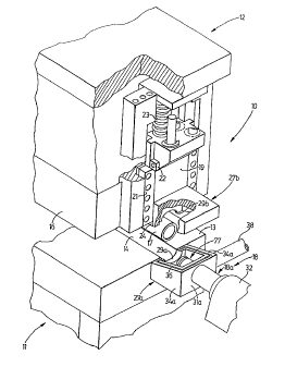
Fig. 1 is a partial perspective view illustrating
a die for expansion forming of tubing together with fill
and pressurization apparatus in open position.
Fig. 2 is partial longitudinal cross-section
through the die and apparatus of Fig. 1, showing the fill
apparatus in closed position and the pressurization device
in retracted condition.
Fig. 3 is a partial perspective and exploded view
of a blocking device used in the apparatus of Figs. 1 and
2.
Fig. 4 is a view corresponding to Fig. 2 with the
pressurization device in extended condition.
Figs. 5 and 6 are enlarged cross sections of the
sealing head of the pressurization device in non-sealing
and sealing states, respectively.
CA 02285115 1999-10-14
- 3 -
Referring to Figs. 1 and 2 an expansion forming
die 10 is shown having a lower portion 11 supported on and
fixed to the surroundings such as the shop floor and an
upper portion 12 movable up and down with respect thereto
by press structure (not shown). For example, the lower
portion 11 may be connected to a fixed frame supported on
the floor. The lower portion 11 may comprise a lower die
section 13 with a generally trough-shaped die cavity
portion 14 therein. An upper die section 16 is also
provided with a die cavity portion and when the sections
are closed together an open-ended die cavity is formed
within which a hollow tube or tubular blank 17 may be
expanded and formed. The blank 17 is placed between the
die sections before closure, and is filled with liquid
(usually water) and is pressurized using fill and
pressurization apparatus provided at each end of the die 10
and indicated at one end generally at 18. The
pressurization is sufficient to expand the blank 17 to form
a replica of the die cavity.
A clamp member 19 is mounted at each end of the
upper die section. Figs. 1 and 2 show the clamp member 19
at one end but it will be appreciated a similar arrangement
is used at the opposite end. Member 19 is supported
through a lost motion linkage comprising vertical slide
structure 21 and a stop 22 such that member 19 is slidable
vertically with respect to section 16 to a downward extent
limited by the stop 22. Compression springs 23 normally
urge the member 19 downwardly to the limiting position
shown in Fig. 1 wherein the lower end 24 of member 19
projects downwardly beneath the upper section 16.
On closure of upper section 16 to an intermediate
position, wherein the opposing surfaces of sections 13 and
16 are separated by a small distance, usually about 10 to
about 250 of the diameter of the blank 17, lower end 24 of
clamp member 19 engages section 13 and is urged upwardly
against the action of the springs 23. The resilient
CA 02285115 1999-10-14
- 4 -
reaction causes the end of blank 17 to be tightly gripped
between the adjacent end portion of the lower cavity 14 and
an arcuate cavity portion 26 formed in the lower side of
member 19.
In the case in which the blank 17 is to be formed
to a cross section which is of oblong rectangular profile
it is desirable to initially form an end of the blank 17 to
an elongated smoothly arcuate profile such as a smoothly
rounded hourglass or elliptical profile. In such case
desirably the end portion of the cavity 14 and the cavity
26 are effective to deform the end of the blank 17 to such
elongated profile. Otherwise, the member 19 and cavity 14
may grip the end of the blank 17 tightly without
substantial deformation. In the example illustrated in the
drawings, the end of the blank 17 is deformed initially to
an elliptical cross-sectional profile.
As shown in the drawings, a box-shaped high flow
- low pressure fluid conduit 27 is provided. A similar
arrangement is provided at each end of the apparatus 10.
The conduit 27 is formed by a sectional fluid conductor
comprising a first or lower conductor section 27a fixed to
the lower section 13 and a second or upper section 27b
connected to the member 19. These sections unite in the
intermediate closure position shown in Figure 2 to form a
closed box.
Each section 27a and 27b may be of similar
construction and preferably each comprises a front wall 28a
or 28b that facilitates securement of the sections 27a and
27b to the section 13 and member 19, respectively, for
example with threaded studs or the like (not shown).
These front walls are formed with a partial
cavity 29a and 29b matching the cavity portions 14 and 26
in the lower section 16 and member 19, respectively.
Usually, there is some variation or tolerance in the
CA 02285115 1999-10-14
- 5 -
lengths of tubular blanks 17 and in order to reduce the
overall length of the apparatus 10, the dimensions of the
walls 28a and 28b are such that, depending on the tolerance
on the length of the blank, the end of the blank falls at a
point along the thickness of the walls 28a and 28b. In the
event that the ends of the blank 17 are deformed to an
elongated profile on intermediate closure of the sections
11 and 12, the walls 28a and 28b react with the blank 17 to
deform it to such profile. Preferably, the cavities 29a
and 29b are each of size or extent sufficient to receive
one half of the external perimeter of the tube 17. For
example, each cavity 29a and 29b may be semi-elliptical.
The front edge of each front wall 28a and b is
substantially flush with the mating planes of the sections
13 and member 19, respectively, to facilitate placement of
the blank 17 between sections 11 and 12 and removal of the
formed blank from between the open sections 11 and 12 at
the end of the forming cycle. The front wall 28a of the
lower section 27a is relatively shallow while a rear wall
31a is relatively deep to accommodate a portion 18a of a
seal head forming part of the apparatus 18, and described
in more detail below. The portion 18a reciprocates axially
of the cavity defined between the cavity portion 14 and 26
in the intermediate closure position described above and
also with respect to a cylinder block 32 fixed with respect
to the surroundings and the portion 11 and hence also fixed
with respect to the section 27a. The portion 18a passes
through an opening 33 in the wall 31a provided with an 0-
ring seal to guard against leakage of liquid around the
portion 18a. The side walls 34a incline upwardly, toward
the upper section 27b, rearwardly from the front toward the
rear. The side walls of the upper section likewise taper
from the front to the rear as seen in side view, so that
the sections 27a and 27b mate together along a plane
inclining upwardly rearwardly. The upper surface of the
front wall 28a, rear wall 31a and side walls 34a are formed
with a groove capturing a generally C-shaped resilient
sealing gasket 36 that engages the lower surface of the
CA 02285115 1999-10-14
- 6 -
walls of the upper section 27b guarding against leakage of
liquid on closure of the sections 27a and b together.
One side wall 34a of the lower section 27a is
formed with an inlet opening 37 to which is connected a
relatively large diameter conduit 38 which is preferably a
substantially rigid tube, for example it may be a metal
pipe. As indicated somewhat schematically in Fig. 2, the
conduit 38 connects through valuing 39 to source 41 capable
of delivering liquid at a relatively high flow rate and at
a relatively low pressure.
In use, when the die portions 11 and 12 are
closed together to the intermediate position, as
illustrated in Fig. 2, the sections 27a and 27b form a box-
like conduit or enclosure 27 about the mouth of the tube 17
gripped between the section 13 and member 19 whether in a
deformed, such as elliptical, profile or in an original
round or circular condition. Valuing 39 may then be
actuated to quickly fill the tube 17 through one end with
liquid through the enclosure 27 from the source 41, at a
high volume flow rate under low pressure, for example at
slightly above atmospheric pressure. At the same time,
valuing similar to valuing 39 connected to a conduit or
enclosure similar to enclosure 27 may be actuated to vent
the opposite end of the tube to the atmosphere, such vent
then being closed at the completion of the liquid fill
operation.
The filled tube 17 may then be sealed and
pressurized using the sealing and pressurization apparatus
described below, or using known forms of sealing and
pressurization apparatus.
Modifications may of course be made to the
apparatus described above in detail. For example, while an
enclosure or conduit 27 having two sections has been
described above, the upper, moving, section 27b may
CA 02285115 1999-10-14
- 7 -
comprise two or more sub-sections moving independently or
in unison from open position to closed positions defining a
conduit or enclosure similar to the enclosure 27.
As noted above, the sealing and pressurization
apparatus comprises a cylinder block 32 fixed relative to
the surroundings, e.g. relative to a frame supported on the
shop floor and supporting the lower portion 11. The block
32 has a bore through it comprising a rear portion 42, a
somewhat narrow middle portion 43 and a wider front portion
44. The rear portion 42 provides a cylinder space housing
a cylinder lining 46 closed at a rear end by an O-ring seal
47, a cylinder head end 48, an 0-ring 49, a gland retainer
51 and a gland 52. The opposite end of the lining 42 is
provided with a seal retainer 53, an 0-ring seal 54, and is
sealed through an 0-ring 56, gland 57, and a thrust gland
retainer 58 secured to the blank 32 with threaded studs 59.
A rod 61 having a bore 62 through it passes
through the block 32. The rod is formed with an enlarged
piston portion 63 engaging snugly within the lining 46.
Inlets adjacent the middle bore portion 43 and the cylinder
head end 48 feed pressurized hydraulic fluid within the
cylinder space to opposite sides of the piston portion 63
whereby the rod 61 may be reciprocated between retracted
and advanced positions as seen in Figs. 2 and 4,
respectively.
Upper and lower mount portions 64 and 66 engage
slots in the outer side of the rear of the rod 61 and are
clamped in tight engagement in the rod 61 by fasteners such
as a threaded stud disposed on each side of the rod out of
the cross sectional plane of, and hence not seen in, Fig.
2. The sides of the portions 64 and 66 engage slidingly on
surfaces 67 extending longitudinally on the block 32 and
prevent rotation of the rod 61 about its axis. An inlet
fitting 68 is secured to the mount portion 64 and 66 with
threaded studs 69. The fitting 68 has a tapped opening 71
CA 02285115 1999-10-14
_ g _
to which can be connected, through a threaded fixture, not
shown, a flexible conduit 72 connected through valuing 73
to a pressure intensifier or other source 74 of liquid,
delivering a low flow rate of liquid at high pressures.
The conduit 72 may be of relatively small diameter since it
does not carry large volume flow rates.
The opposite or front end of the rod 61 has a
relatively narrow stepped down diameter circular end
portion 76 which carries a seal head generally indicated at
77. In the example illustrated, the head 77 is of
elliptical cross section to engage the correspondingly
deformed end of the tube 17, but in the case in which the
tube end is maintained round or circular the head 77 may of
course be of circular cross section. The head 77 in the
present instance comprises a sleeve 78 with a circular bore
slidable axially on the rod end 76 and having an outer
surface which is elliptical in cross sectional profile An
0-ring 79 is captured within the sleeve 78 to disallow flow
of high pressure liquid externally of the rod 61. The
inner side of the sleeve 78 adjacent its forward end is
formed with an annular recess 81, the rear side of which
provides a stop surface 81a.
In the preferred form as shown, an elastomeric
ring member 82 likewise with an elliptical outer profile
and a circular section bore, is disposed over a collar
member 83 having a thin annular collar portion 84 extending
inwardly a small distance beyond the inner end of the
elastomeric member 82 and normally spaced from the stop
surface 81a as seen in Fig. 5, and an inner shoulder
portion 86 having a circular inner bore and elliptical
outer profile. The collar 83 is axially slidable on the
rod 61 and preferably its forward end is smoothly convexly
rounded as seen at 87 to facilitate insertion into the open
end of the tube 17. A C-shaped nose retainer clip 88 seats
in a correspondingly shaped slot in the end of the rod end
portion 76 and maintains the shoulder portion 86 in lightly
CA 02285115 1999-10-14
- 9 -
compressed condition against the elastomeric member 82. In
such condition, the outer side of the elastomeric member 82
is preferably nested inwardly between the peripheries of
the shoulder 86 and sleeve 78 as seen in Fig. 5.
In use, the seal head 77 is inserted into the
open end of the tube 17 to be sealed, by extension of the
rod 61, as seen in Figs. 4 and 5. Blocking means, such as
the circular portion 18a are then applied to the sleeve 78
to resist its retraction while the rod 61 is retracted.
such blocking means may be, for example, as described in
the above-mentioned U.S. patent 5,235,836, or may be the
preferred form of blocking means described hereinafter in
more detail especially with reference to Fig. 3. As the
shoulder portion 86 retained by the clip 88 retracts
relative to the sleeve 78, the elastomeric member 82 is
deformed compressively to expand radially outwardly into
sealing contact with the inner side of the tube 17. The
collar portion 84 closes on the stop surface 81a as seen in
Fig. 6 to limit the deformation force applied to the seal
member 82 and to avoid risk of damage to the seal member
and excessive forces being applied to the wall of the tube
17.
Various modifications may of course be made. For
example, although with considerably less advantage instead
of having a collar portion 84 engaging a stop surface 81a
other forms of stop member on or connected to the rod 61
may be used engageable against a stop surface on or
connected to the sleeve 78. Alternatively, external forms
of compression limiting device may be used as described in
U.S. patent 5,235,836 referred to above. Moreover, instead
of sealing on the inner wall of a tube 17 the seal head 77
and sliding force-limiting collar 83 as described in detail
above may be modified as will be appreciated by those
skilled in the art to form a seal on the outer side of the
wall of the tube 17, as described and shown in the above-
mentioned U.S. patent 5,235,836.
CA 02285115 1999-10-14
- 10 -
In such case, as will be appreciated the outer
sleeve portion may engage and displace a collar similar to
the collar 83 while the inner rod portion may provide the
stop surface engaged by the collar at the limit of
compression of the elastomer seal.
In the preferred form, the blocking portion 18a
comprise a cylinder 89 as seen in Fig. 3 having a bore
therethrough having a relatively wide rear portion 91 which
accommodates the main portion of the rod 61 and a narrower
front portion 92 which accommodates the narrow front end
portion 76. The cylinder 89 is normally maintained in
engagement with the front edge of the main portion of rod
61 as seen in Fig. 5 by the compressive force exerted by
the clip 88. The bore portion 91 is formed with a slot or
keyway 93 slidably receiving a key 94 secured to the rod 61
whereby the cylinder is non-rotatable relative to the rod
61 and hence also relative to the surroundings. The
cylinder 89 is thereby prevented from twisting the
components of the seal head 77 around the axis of the rod
61 out of alignment with the aperture defined between
section 13 and member 19 or between walls 28a and 28b.
The cylinder 89 is received telescopingly within
an outer cylinder 96 which is housed within the wider front
portion 44 of the bore within the block 32, and the
cylinder 96 has a reduced diameter inner rear end portion
97 which journals on or relative to gland member 57. The
outer side of the front end of the cylinder 96 is retained
and supported rotatable within a guide bushing 98 connected
on front of the block 32.
The inner side of the outer cylinder 96 is formed
with a series of radially inwardly projecting abutment
members 99, for example three members 99, spaced
equiangularly with respect to the axis of the cylinder 96.
The outer side of a rear portion of the cylinder 89 is
formed with a like number of equally spaced axially
CA 02285115 1999-10-14
- 11 -
extending channels 101 within which the members 99 can
normally run freely as the cylinder 89 telescopes in and
out of the cylinder 96. Each channel 101 terminates at the
rear end in a circumferentially extending recess 102
S providing a radially extending stop surface 103.
For rotating the cylinder 96 about its axis, a
ring gear 104 is secured on the inner end of the outer
surface of the cylinder 96. The gear 104 is driven by a
toothed rack 106 running in a transverse slot 107 in the
block 32. A reciprocating drive 108, for example an
indexing cylinder and piston arrangement is connected to
the rack 106 whereby the rack 106 may be reciprocated to
drive the gear 104 and hence the outer cylinder 96 in
oscillatory rotation about its ring.
In a typical cycle of operation of the apparatus,
starting with the fill and pressurization apparatus in the
position shown in Figs. 1 and 2, a tubular usually
cylindrical blank 17 is placed between the die portions 11
and 12 in open condition as seen in Fig. 1. The portions
11 and 12 are then closed together to an intermediate
position so that the end of the tube 17 is deformed to an
elliptical cross section and gripped between an outer or
throat portion of the lower cavity portion 14 and the
member 19, as well as between the walls 38a and 28b as the
upper section 27b drops onto and seals with the lower
section 27a to form the box-like enclosure 27 as seen in
Fig. 2. The tube 17 is then filled with liquid through the
conduit 38 in the high flow low pressure fill operations
described above. Before this fill, the valuing 73
connected to the bore 62 of the rod 61 is closed.
Pressure is applied to the cylinder housing the
piston 63 so that the rod 61 is driven forwardly as seen in
Fig. 4 so that the seal head 77 enters the end of the tube
17 as seen in Figs. 4 and 5. As it moves forward, the rod
61 gathers the cylinder 89 which extends out of the
CA 02285115 1999-10-14
- 12 -
cylinder 96 as seen in Fig. 4. The drive 108 is operated
to rotate the cylinder 96 and engage the abutment members
99 in the recesses 102. The drive to the piston 63 is
reversed tending to retract the rod 61 rearwardly as seen
in Fig. 6. Return movement of the sleeve 78 and cylinder
89 is blocked by engagement of the abutment members 99 on
the stop surfaces 103 so that the compression and sealing
of the elastomer member 82 within the tube 17 described
above takes place. As will be appreciated, a similar
gripping, deformation, sealing and pressurization
arrangement is employed at each end of the tube 17, with
the result that the sealing effected by the seal heads 77
isolates the interior of the tube 17 from the interior of
the box-like enclosures 27 and the high flow - low pressure
circuit 41.
The valuing 73 and low flow - high pressure
source 74 are operated to apply a pre-pressure to the
interior of the tube 17, for the purpose of avoiding
pinching of the tube 17 between the upper and lower die
sections 16 and 13 on full closure as described in the
above-mentioned U.S. patent Re. 33990. The sections 13 and
16 are closed fully, and the pressure attained within the
tube 17 may be limited during die closure by a pressure
relief valve connected to the line 72 or included in the
valuing 73. During full closure, the clamp member 19 is
displaced upwardly somewhat relative to the upper die
section 16 against the action of the springs 23. The
pressure relief valve is then disabled and the high
pressure source 74 operated to apply pressure to the tube
17 sufficient to expand it permanently to the shape of the
die cavity formed between the sections 13 and 16.
The pressure within the tube 17 is relieved,
drive 108 is operated to unblock return movement of the
cylinder 89 and the piston 63 driven rearwardly to the
position of Fig. 2. The portions 11 and 12 are opened, the
formed blank 17 is removed and the above described cycle of
CA 02285115 1999-10-14
- 13 -
operation can then be repeated.