Note: Descriptions are shown in the official language in which they were submitted.
CA 02285180 2006-O1-12
INTRAVAGINAL DRUG DELIVERY SYSTEM
AND DISCHARGE COLLECTION DEVICE
BACKGROUND
The present invention relates to a system for intravaginal delivery of drugs
and other
substances, including but not limited to spermicides, germicides, virucides,
medicants, anti-
infection agents, hormones, deodorizing materials, lubricants, steroids, anti-
bacterial agents, and
other pharmacological agents, chemical, natural, or homeopathic agents, and
anesthetics. The
invention also relates to an improved device for reliably, comfortably and
conveniently
introducing drugs and/or other substances into the vagina.
The prior art has failed to provide a satisfactory system for delivering drugs
and other
substances to the vagina. Among other things, the prior art has failed to
provide an effective
intravaginal drug delivery device that can be economically mass produced,
easily handled, and
worn comfortably within the vagina. Although a number of contraceptive
CA 02285180 1999-09-28
WO 98/43562 PCT/US98/06014
devices have been designed to deliver spermicidal substances and other active
agents, such
prior art devices are all unsatisfactory, for a variety of reasons.
U.S. Patent No. 4,785,804 (Tl~k), for example, refers to a disposable cervical
cap which is pre-treated with nonoxyl-9 or other spermicides. The T1T device
has a thin
flexible dome and an integral rim. The rim has an inwardly directed annular
groove for
gripping the cervix wall to keep the cap in position. In the TlaTuek_ device,
the dome and
the rim provide a contraceptive barrier, and the spermicide is used to
increase the
contraceptive effect. An integrally molded loop is provided to remove the
cervical cap.
According to Tla-nek, a string, ring or tab could also be used to remove the
device from the
vagina. The Tla~e_k cap is unsatisfactory because among other things it
requires a removal
device which increases its complexity and cost of manufacture. In addition,
the Tla~k
device may be difficult to locate and remove from its installed position
gripping the cervix,
and the manner in which its annular groove is located snugly over the cervix
may cause
discomfort in some users.
U.S. Patent No. 4,526,578 (~y~g) discloses another disposable device for
delivering spermicide. The Yy~ug device is in the form of a dome-shaped
occlusive
diaphragm that fits snugly within the vagina, covering the cervix and part of
the anterior
vaginal wall. The prior art ~ diaphragm has an annular reservoir formed of
porous
material. Spermicide is located within the porous, reservoir. A film structure
is integrally
formed with the annular reservoir. According to Wong, the film structure may
also
incorporate spermicide. The active spermicidal agent may be added to the film
structure
during its formation.
The yy~lg device has several disadvantages. First, its annular reservoir would
be
complex and difficult to produce economically. Moreover, the diaphragm-shaped
device
would be difficult to collapse and insert by hand into the vagina. The annular
reservoir has
a circular crass-section and consequently would tend to twist if diametrically
opposite
portions were pinched toward each other. Moreover, the reservoir would tend to
slip out
from between the user's fingertips. Another problem with the y~~n,g device is
that its film
material could not be relied upon to fold into a narrow, low-profile
configuration for
2
CA 02285180 1999-09-28
WO 98/43562 PCT/US98/060.14
convenient, comfortable insertion. Moreover, the snug internal fit for which
the Wong
device is designed could cause discomfort with some users.
U.S. Patent No. 5,044,376 () discloses a contraceptive diaphragm. The
device has a tensioning spring and a receptacle for receiving a foam pad. The
pad contains
spermicide that is released by diffusion into the vagina. A retaining ring is
provided for
holding the pad in place. The pad and the retaining ring add complexity to the
Shleld~
device and would make it relatively difficult to manufacture. Another
disadvantage of the
Shield. device is that it would not be easily compressible into a low profile
configuration for
insertion. In particular, the device could not be compressed into a figure-
eight-shaped
configuration with the pad substantially located within the spring. Moreover,
the . l ldc
device is generally bulky and does not appear to have been designed for
comfort.
also discloses a drug delivery device in the form of a cervical cap.
U.S. Patent No. 4,822,616 (~im~~) discloses a vaginal ring for
time-released introduction of steroid hormones. The Zimul~rmann ring is formed
of
injection molded silicone elastomer. The cross-section of the ring is kidney-
shaped. The
Zrimtnsrmsann ring is formed in several layers. This complex, multi-layer
construction
would make it relatively di~cult and expensive to manufacture. Moreover, the
ring's flat
profile would be difficult to handle. The height of the ring is less than its
thickness.
Therefore, it would be relatively di~cult to compress the ring into a figure-
eight-shaped
position for insertion. The ring would tend to twist and slip out from between
the user's
fingers. Another disadvantage of the Z~,~ ring is that it does not appear to
have
been designed for comfort. Morcover, the prior art ring has no film covering
its central
open space. Consequently, the Zimmermanu device has reduced surface area
available for
delivering drugs or any other substances, and the device could not be used to
collect or contain fluid.
Other prior art systems for delivering substances into the vagina are shown by
U.S. Patents Nos. 4,630,602 (~tri~kman), 4,589,880 (IZuna), 4,553,972
(VickeN),
4,311,543 (~trisl~man '543), 4,286,587 (I~ng '587), 4,219,016 (I2rQ1?ish),
3
CA 02285180 1999-09-28
WO 98/43562 PCT/US98/06Q14
4,198,976 (Drobish '976), 3,854,480 (), and British Patents Nos. 260,600
(Fiessler) and 21,588 (Fib).
The present invention alleviates to a great extent the disadvantages of the
known substance delivery devices by providing a device which is easily
compressible to a
low profile insertion configuration, and which has a rim whose height is
greater than its
thickness, and which is arranged to provide an elastomeric outward holding
force to hold it
in position.
The invention may be used to deliver drugs and/or other agents topically
and/or systematically through vaginal mucosa. The invention may also be used
to effect
intravaginal drug delivery of time released and non-time released medicants
for all diseases
of the vagina and other reproductive organs and any and all diseases of the
entire female
anatomy. The invention may be used by both menstruating and non-menstruating
females.
For example, for the treatment of yeast and fungal infection, medication can
be delivered
without interruption during menstruation. Additionally, the invention may be
used for
intravaginal delivery of hormones for birth control and for treatment of the
female
anatomy, such as during menopause.
The invention may also be used for the delivery of time released and non-time
released deodorizing materials for odor prevention, for the delivery of
lubrication, and for
the delivery of steroids, and-bacterial agents or any pharmacological agent,
chemical,
natural, or homeopathic agcnts. Moreover, the invention may be used for
intravaginal
delivery of anesthetic for local surgical procedures and for general surgical
procedures and
for the delivery of pain relieving medication for intermittent and chronic
pain, as well as for
drug delivery for pregnant women for any and all prophylaxis and illnesses
particular to the
fetus and/or mother-to-be.
Moreover, the present invention may be used to provide a safe sex barrier, in
particular as a barrier during sexual contact to aid in the prevention of the
transmission of
4
CA 02285180 1999-09-28
WO 98/43562 PCT/US98/06014
diseases. The effectiveness of the invention in this regard may be enhanced by
using a
device with, or for the delivery of, non-oxynol 9 or other specific medicants.
The invention may also be used for the delivery of drugs and other substances
in
veterinary applications including primates other than humans and other
animals.
Moreover, the invention may be employed as an aid to conception for humans,
primates, and other animals. Conception can be aided by either using a
collector for
retaining sperm in the vaginal vault after intercourse or by placing sperm in
or on a delivery
device and then inserting it in the vaginal vault. This is different from and
not a substitute
for the medical procedures of artificial insemination that are required in
certain
circumstances and that are done by doctors in a clinical/hospital setting.
In one aspect of the invention, a drug delivery device is provided with a rim
which has a generally rectangular cross-section and which is readily
compressible into a
narrow, figure-eight-shaped configuration with reduced tendency to twist or
slip from
between the user's fingcrs.
In another aspect of the invention, a flexible film is attached to the rim.
The
film may be used to provide surface area for drug delivery. The film may also
be used to
close off the device to collect fluid such as menstrual discharge. The film is
preferably
collapsible so as to be substantially enclosed within the rim to provide a low
profile during
insertion and when the device is located within the vaginal canal.
In another, separate aspect of the invention, the rim and the film may be
arranged such that compressing diametrically opposed portions of the rim
toward each
other causes a leading portion of the rim to dip downwardly to facilitate
proper insertion of
the device under the cervix.
In another aspect of the present invention, the dimensions and materials of
the
device, including the dimensions and materials of the rim, are selected so as
to optimize the
device's convenience, comfort and reliabiliry. The structure of the present
invention may
be sized for comfort during wearing while still being held in position by
compression of the
vaginal wall on the rim. The comfort is achieved in part by a rim that becomes
softened or
CA 02285180 1999-09-28
WO 98/43562 PCT/US98/06914
relaxed somewhat at body temperature. In a preferred embodiment of the
invention, the
reservoir also becomes softened at body temperature, which enhances the
device's comfort.
In a preferred embodiment of the invention, a single size device may be
adequate for use for a range of sizes of vaginal canals. Even when the device
is used to
collect menstrual fluid, a tight fit may not be needed to inhibit the passage
of menstrual
fluid around the rim.
Another advantage of the present invention is that, because it may be made of
a
material that is chemically inert and non-toxic, it should not be prone to
health problems
that other products with absorbent materials seem to cause. Moreover, the
material of the
present invention may allow for adjustment to individual shapes and afford
excellent
comfort while maintaining its original form. The present invention may be
constructed of
Latex, polymers, and/or elastomers.
The present invention also relates to a discharge collection device that is
convenient to use, comfortable to wear, and reliable. The present invention
may be used to
seal off the blood environment to inhibit the growth of bacteria and entry of
air and thus
hinder the odor which results from the oxidation and decomposition of
menstrual flow.
The present invention also relates to a specimen collector to collect blood
and/or vaginal, cervical and/or uterine discharge.
Another object of the invention is to provide a device for vaginal discharge
collection and/or intravaginal substance delivery, with the device being
designed for
economical mass production, such that the device can be conveniently disposed
of after a
single use.
It is yet a further object of the present invention to provide a discharge
collector
with any of the foregoing advantages and which provides time released and non-
time
released dosages of substances for both menstruating and non-menstruating
females so that
there will be substantially no interruption of treatment, which substance may
be, for
example, medication, lubrication, deodorants, hormones and analgesics.
6
CA 02285180 1999-09-28
WO 98/43562 PCT/US98/06014
It is another object of the present invention to provide a drug delivery
device
which does not require individual fitting for each user and which may be
produced
economically enough to be used as a disposable product.
It is yet another object of the present invention to provide a drug delivery
device which is easy to insert and remove without scraping delicate tissue.
It is still another object of the present invention to provide a drug delivery
device which also provides a barrier against the blood environment.
It is a further object of the present invention to provide a drug delivery
device
which is light weight without the bulk associated with other devices and which
once
inserted cannot be felt by the user so that the user is free of the annoying
awareness
associated with other devices.
It is another object of the present invention to provide a discharge collector
with any of the foregoing advantages and which is inexpensive and therefore
available to all
women.
Other objects and advantages of the present invention will become apparent
from the following detailed description and drawings which illustrate
preferred
embodiments of the present invention.
FIG. I is a top view of a first preferred embodiment of a discharge collector
according to the present invention.
FIG. 2 is a partial cut-away side view of the collector of FIG. 1.
FIG. 3 is a top view of a second preferred embodiment of a discharge collector
according to the present invention.
FIG. 4 is a partial cut-away side view of the collector of FIG. 3.
FIG. 5 is a top view of a third preferred embodiment of a discharge collector
according to the present invention.
FIG. 6 is a partial cut-away side view of the collector of FIG. 5.
7
CA 02285180 1999-09-28
WO 98/43562 PCT/US98/06014
FIG. 7 is a top view of a fourth preferred embodiment of a discharge collector
according to the present invention.
FIG. 8 is a partial cut-away side view of the collector of FIG. 7.
FIG. 9 is a view of the collector of FIG. 3 in place in the vaginal canal.
FIG. 10 is a top view of a fifth preferred embodiment of a discharge collector
according to the present invention.
FIG. 11 is a partial cut-away side view of the collector of FIG. 10.
FIG. 12 is a perspective view of a discharge collection device according to
another preferred embodiment of the present invention.
FIG. 13 is a top view of the discharge collection device of FIG. 12.
FIG. 14 is a cross-sectional view taken along the line 14-14 of FIG. 13.
FIG. 15 is a side view of the collection device of FIG. 12 in place within the
vaginal canal.
FIGS. 16, 17 and 18 are a perspective view, a top view and a side view,
respectively, of the discharge collection device of FIG. 12, in a compressed
configuration
ready for insertion.
FIG. 19 is a perspective view of an intravaginai drug delivery ring according
to
the present invention.
FIG. 20 illustrates the percentage of metronidazole released from Kraton~
films
containing 0.100, 0.500 and 1.000 gram metronidazole.
FIG. 21 illustrates the percentage of miconazoie nitrate released from Kraton~
films containing 0.100, 0.500 and 1.000 gram miconazole nitrate.
FIG. 22 is a cross-sectional view of a device constructed in accordance with
another embodiment of the invention.
FIG. 23 is a partial cross-sectional view of a device constructed in
accordance
with another embodiment of the invention.
FIG. 24 is a partial cross-sectional view of a device constructed in
accordance
with yet another embodiment of the invention.
8
CA 02285180 1999-09-28
WO 98/43562 PCT/US98/06014
FIG. 25 is a partial cross-sectional view of a device constructed in
accordance
with yet another embodiment of the invention.
FIG. 26 is a partial cross-sectional view of a device constructed in
accordance
with yet another embodiment of the invention.
FIG. 27 is a partial cross-sectional view of a device constructed in
accordance
with yet another embodiment of the invention.
FIG. 28 is a partial cross-sectional view of a device constructed in
accordance
with yet another embodiment of the invention.
A discharge collector 10 constructed in accordance with one aspect of the
present invention is shown in FIGS. 1 and 2. The collector 10 includes a
resilient circular
rim 11. The body 14 of the collector 10 includes a cup-shaped membrane wall 15
extending downward from the rim and terminating in a reservoir 12 to form a
collection
space 19. The membrane wall 15 includes at its bottom a reservoir I2 that is a
bubble-like
protrusion extending at edge 18 from the body 14 surface defined by the
membrane
wall 15.
The collector 10 is composed of a latex rubber and may be formed by a latex
dipping process in which a mandrel is dipped into a tank of coagulating agent,
and then
dipped into a tank of liquid rubber latex which coagulates on the mandrel. It
is then
subjected to drying and curing with heat and the device is removed from the
mandrel. The
material of the preferred embodiment is elastomeric, such as a latex rubber
and similar
materials. Materials for the collector may be chosen which may be impregnated
with a
substance to be delivered during use of the device. Such materials are
generally known,
such as described in U.S. Patent No. 4,589,880. Other suitable methods of
making the
collector may be used, such as by molding.
. The rim 11 of the collector 10 is formed entirely of solid latex rubber.
However, as discussed below with reference to other preferred embodiments,
alternative
rim constructions may be used. The diameter of the rim is preferably about two
to about
9
CA 02285180 1999-09-28
WO 98/43562 PCT/US98/06014
four inches (about five to about ten centimeters). The thickness of the rim is
preferably less
than about one quarter inch (about six millimeters) to result in the greatest
degree of
comfort to the user. The thickness of the wall, which is substantially
impervious to liquid,
of the body 14 and the reservoir 12 is preferably more than about one ten
thousandth of an
inch (about two microns).
The depth of the collector 10 from the rim 11 to the bottom of the reservoir
12
is preferably about one to three inches (about two to eight centimeters). The
depth of the
reservoir 12 from the edge 18 to the bottom of the reservoir 12 is preferably
about one
sixteenth to one half of an inch (about two millimeters to about thirteen
millimeters). The
volume of the collection space 19 is preferably about one to about two ounces
(about
fifteen to about thirty milliliters).
The thickness and diameter of the rim will depend upon the stiffness of the
material used as the rim should be resilient and flexible to be inserted into
position and to
exert sufficient force to hold the collector 10 in position during use as
discussed further
below in reference to FIG. 9. The thickness of the body 14 will depend upon
the
properties of the material used so that the body 14 will have sufficient
strength and
flexibility.
Refer to FIGS. 3 and 4, there being shown a second preferred embodiment of a
discharge collector, generally designated by reference numeral 20, according
to the present
invention. The collector 20 includes a resilient circular rim 22. The body 24
of the
collector 20 is an impervious cup-shaped membrane wall extending downward from
the
rim 22 to form a collection space 29. The construction of the collector 20 is
essentially the
same as the collector 10, but the collector 20 does not include the reservoir
feature. The
device 20 may be used to collect discharge, including uterine, cervical,
vaginal and/or
mucosal discharge, and including blood and tissue sloughed off from a woman's
uterus
during menstruation.
In operation, the device 20 is inserted into the woman's vaginal canal 201
(FIG. 9) such that portions of the rim 22 are located behind the cervix 202
and behind the
pubic bone 205. In this position, the resilient rim 22 exerts a resilient,
radially outward
CA 02285180 1999-09-28
WO 98/43562 PCT/ITS98/06014
force on the wall of the vaginal canal 201. The rim 22 also contacts and
exerts a force
against the wall of the vaginal canal 201 at points around the periphery of
the rim 22,
which force is sufficient to effectively prevent menses or other discharge
from passing
between the rim 22 and the vaginal canal wall 20I . The resilient outward
force of the rim
22 is sufficient to maintain the device 20 in its illustrated position.
The outward force of the resilient rim 22 is also sufficient to effectively
prevent
discharge from passing between the rim 22 and the wall of the vaginal canal
201.
Therefore, discharge from the cervix 202 is collected within the cup-shaped
body 24. After
a period of time, the device 20 is removed from the vaginal canal 201, and
disposed of
along with the collected discharge. A new device 20 is then inserted into the
position
illustrated in FIG. 9.
The amount of discharge that can be collected within the body 24 is a function
of the device's depth 23 (FIG. 4). Increasing the depth 23 increases the
amount of
discharge that can be collected within the device 20, and therefore increases
the amount of
time that the device 20 can be used. An increased depth 23 also makes it easy
to remove
the device 20, as explained in more detail below. However, the depth 23 cannot
be so
great as to cause discomfort or make it difficult to insert the device 20 into
the vaginal
canal 201. Generally, the depth 23 of the device 20 measured from the top of
the rim 22
to the bottom of the body 24 is at least about one and one-half centimeters
and no more
than about eight centimeters. A preferred range for the depth 23 is about four
to about six
centimeters.
The cross-sectional thickness of the round rim 22 will depend upon the
stiffness
of the material used. The rim 22 should be flexible enough to be easily and
reliably
inserted into position, and yet stiff enough to exert sufficiently radially
outward force to
hold the device 20 in position and to adequately prevent discharge from
leaking around the
rim 22, i.e., between the rim 22 and the wall of the vaginal canal 201. In the
illustrated
embodiment, the round rim 22 is formed entirely of an appropriately stiff
elastomer, with a
thickness of about six millimeters.
11
CA 02285180 1999-09-28
WO 98/43562 PCT/US98106014
The wall of the cup-shaped body 24 should be thick enough to provide the
desired strength, flexibility, durability and fluid imperviousness. In the
illustrated
embodiment, the body 24 is formed of latex rubber and is about two mils thick.
The device 20 may be formed by a latex dipping process involving the following
steps: dipping a mandrel into a tank of coagulating agent; then dipping the
mandrel into a
tank of liquid rubber latex which coagulates on the mandrel; drying and curing
the
coagulated rubber latex; and removing the cured device from the mandrel. Other
suitable
methods of making the device 20, such as molding, may be used.
FIGS. 5 and 6 show a third preferred embodiment of a vaginal discharge
collector, generally designated by reference numeral 30, according to the
present invention.
The collector 30 includes a resilient circular rim 31. The body 34 of the
collector 30 is a
cup-shaped membrane wall extending downward from the rim to form a collection
space
39. The membrane wall includes at its bottom a reservoir 32 that is a bubble-
like
protrusion on the body 34 surface defined by the membrane.
The collector 30 includes a closure means in the form of two membranes 33 to
inhibit menses or other vaginal discharge from exiting the collection space
39. Membrane
33 extends across the circular area defined by the rim 31 forming, between
their edges 36,
a slit 35 which extends across the diameter of the rim 31. The edges 36 are
curved so that
the width of slit 35 is greatest at the center and the edges 36 come together
at the rim 31.
The area of the slit 35 is preferably between about five percent and about
ninety five
percent of the area defined by the rim 31. The sizes of the slit 35 and the
membrane 33
are chosen such that the slit 35 is large enough for fluid to enter the
collector 30 and the
membranes 33 inhibit the exit of fluid to the desired extent. The thickness of
the
membranes 33 is preferably greater than about one ten thousandth of an inch
(about two
microns). The membranes 33 may be used for drug delivery, and the size and
thickness of
the membranes 33 may be chosen to meet the dosage needs.
Refer now to FIGS. 7 and 8, there being shown a fourth preferred embodiment
of a discharge collector, generally designated by reference numeral 70,
according to the
present invention. In FIG. 7, a top view of the collector 70 is shown. The
collector 70
12
CA 02285180 1999-09-28
WO 98/43562 PCT/ITS98/06014
includes a resilient circular rim 71. The body 74 of the collector 70 is a cup-
shaped
membrane wall extending downward from the rim to form a collection space 79.
The
' membrane wall includes at its bottom a reservoir 72 that is a bubble-like
protrusion on the
body 74 surface defined by the membrane.
The collector 70 includes a closure means in the form of a membrane 73 to
inhibit the exit of menses or other discharge from exiting the collection
space 79. The
membrane 73 extends around the periphery of the circular area defined by the
rim 71
forming with its edge 76 a circular opening 75. The width of the membrane 73
between
edges 76 and rim 71 is preferably about five percent to about ninety five
percent of the
diameter of the rim 71.
Refer now to FIGS. 10 and 11, there being shown a fifth preferred embodiment
of a discharge collector, generally designated by reference numeral 150,
according to the
present invention. In FIG. I0, a top view of the collector 150 is shown. The
collector 150
includes a resilient circular rim 151. The body 154 of the collector 150 is a
cup-shaped
membrane wall extending downward from the rim to form a collection space 159.
The
membrane wall includes at its bottom a reservoir 152 that is a bubble-like
protrusion on
the body 154 surface defined by the membrane.
Note that the body 154 is deeper, preferably about three to about four inches
(about eight to about ten centimeters) in depth, and has a larger capacity,
preferably about
w.
two to four ounces (about thirty to sixty milliliters), than the collector 10
of FIGS. 1 and 2.
This embodiment is particularly useful for over-night use or when relatively
large volumes
of discharge are to be collected.
The collector 150 includes a closure means that includes two membranes 153
and 163. The upper membrane 153 extends over approximately half of the area
defined by
the rim 151 and has no or relatively little slack so that it extends
approximately
horizontally. The lower membrane 163 extends over more than half of the area
defined by
the rim 151. The edge 166 of the membrane 163 extends underneath the upper
membrane 153. The slit 155 formed between the edge 156 of the membrane 153 and
the
edge 166 of the membrane 163 allows discharge to drain into the collection
space 159.
13
CA 02285180 1999-09-28
WO 98/43562 PCT/US98/06014
However, as collected fluid moves upward towards exiting the device, force is
exerted
upward on the membrane 163 to cause it to contact the underside of membrane
153. In
this manner, the closure means shuts the slit 155 to inhibit the exit of fluid
from the
collection space 159.
All of the collectors illustrated in FIGS. I through I1 may be formed of the
same latex rubber material. However, the materials and the size and thickness
of the
various components of the invention should be chosen for the considerations
discussed
with respect to one or more of the preferred embodiments. These conditions may
be
applicable to each of the preferred embodiments described above, as well as
other
embodiments of the present invention, even though not individually stated for
each
embodiment in conjunction with its description above. Also, various features
of the
illustrated devices may be used with other devices. The present invention is
not limited to
the embodiments illustrated and described in detail herein.
The collectors shown in FIGS. 1-11 may be used to deliver drugs and other
substances into the vagina, and the collectors may be used exclusively for
substance
delivery. In other words, the devices may be used for both purposes or they
may be used
solely for substance delivery. With respect to use of the illustrated
collectors for the
delivery of drugs and other substances, the substances may be applied to the
collectors in a
number of ways. The substance, which may be,a therapeutic agent, may be
applied to a
collector by mixing the substance or its precursors with the material of the
collector's body,
rim, reservoir, membrane, and/or other portion during manufacturing, such as
prior to
forming the collector during a molding operation by mixing the substance with
the
ingredients, whether dry or liquid, to be molded. Another way to apply the
substance is to
inject, impregnate, or absorb it partially or completely through the material
(or cavities or
porous portions thereof) of the collector's body, rim, film reservoir, and/or
other portions
after such portions have been formed. Yet another way to apply the substance
is to coat
portions of the collector surface with the substance.
Refer now to FIGS. 12 and 13, there being shown a device 250 constructed in
accordance with another, presently preferred embodiment of the present
invention. The
14
CA 02285180 1999-09-28
WO 98/43562 PCT/IJS98/06014
device 250 may be used to collect fluid or it may be used to deliver
substances into the
vagina or it may be used for both purposes. The device 250 is formed of a
thick
elastomeric rim 252 and a highly flexible film or reservoir 254. The reservoir
254 is formed
of a thin, impervious, elastomeric film material and is sealingly connected to
the rim 252.
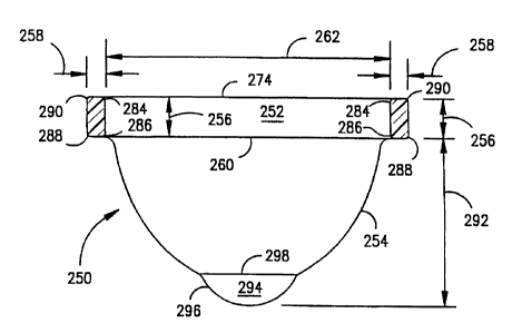
As illustrated in FIG. 14, the rim 252 has a rectangular cross section (with
substantially
parallel inner and outer sides, and with rounded edges), with its height 256
being
substantially greater than its thickness 258.
The amount of discharge typically generated during a menstrual cycle is two to
eight tablespoons (thirty to one hundred twenty milliliters). The exemplary
devices 250,
10, 20, etc. illustrated in this application are designed to be worn
internally for about four
hours. During this four hour time period, a woman typically discharges about
one
teaspoon (five milliliters) of menstrual fluid, although much larger volumes
of liquid may
be discharged during heavy flow periods.
In operation, the device 250 is inserted into the woman's vaginal canal 201
(FIG. 15) such that portions of the rectangular rim 252 are located behind the
cervix 202
and behind the pubic bone 205. In this position, the rim 252 is slightly
compressed and
therefore exerts an elastomeric, radially outwardly directed force on the wall
of the vaginal
canal 201. This force maintains the device 250 in its illustrated position
during use, and
prevents discharge from escaping between the rim 252 and the wall of the
vaginal
canal 201.
The reservoir 254 can be extended to assume a cup-shaped configuration, as
illustrated in FIGS. 12 and 13. However, when the device 250 is in its
collection position
within the vaginal canal 201 (FIG. 15), the reservoir 254 is collapsed
inwardly toward the
cervix 202 by the walls of the vaginal canal 201. In this position, i.e.,
while discharge from
the cervix 202 is being collected within the device 250, the reservoir 254
remains in its
collapsed configuration essentially coplanar with the bottom edge 260 of the
rim 252.
Thus, in FIG. 15, the reservoir 254 is essentially hidden from view behind the
rim's bottom
edge 260.
CA 02285180 1999-09-28
WO 98143562 PCT/US98/06014
Discharge (such as vaginal and/or cervical discharge) is collected within a
generally cylindrical space defined within the rim 252. This collection space
is a virtual
space in the sense that the rim 252 separates the walls of the vagina 201 to
create a
collection space where there is no space otherwise. In the illustrated
embodiment of the
invention, the inner diameter 262 of the rim 252 is approximately sixty two
millimeters,
and the collection volume is approximately thirty milliliters. The volume of
this collection
space is approximately equal to the height 256 of the rim 252 times the area
surrounded by
the rim 252. The reservoir 254 does not contribute significantly to the volume
of the
collection space, except that folds within the reservoir 254 may provide a
trickling down
effect, as explained below. While the device 250 is collecting discharge, the
primary
function of the reservoir 254 is only to seal off the bottom of the device
250. The ability of
the reservoir 254 to assume a collapsed configuration allows the device 250 to
be inserted
and worn internally with greater comfort. Another advantage of the collapsed
configuration is that it provides additional surface area for substance
delivery purposes.
To insert the device 250 into the vaginal canal 201 adjacent the cervix 202,
diametrically opposed portions 264, 266 (FIGS. 16 and 17) of the rim 252 are
pressed into
contact with each other between two of the user's fingers 268, 270 (which may,
for
example, be the user's thumb 268 and middle finger 270), such that the rim 252
assumes a
low profile, figure-eight-shaped configuration. In the low profile
configuration, the film
reservoir is substantially collapsed within the rim or located adjacent the
rim during
insertion of the device, which makes it easier and more comfortable to insert
the device. As
used herein, the term "low profile" configuration means a configuration like
that shown in
FIG. 17, where the rim 252 is compressed into a narrow figure-eight-shaped
configuration
with substantially no twisting, and with the film reservoir 254 substantially
collapsed within
the rim 252 or located adjacent the rim 252 during insertion of the device.
The thinness
and flexibility of the reservoir 254 contributes to the ability of the device
to assume the low
profile configuration during insertion.
The compression applied by the fingers 268, 270 is not released (i.e., the
portions 264, 266 remain in contact with each other) until a leading portion
272 of the rim
16
CA 02285180 1999-09-28
WO 98/43562 PCT/US98/06014
252 is in position behind the cervix 202. The compression applied by the
fingers 268, 270
is then released, allowing the rim 252 to elastomerically restore itself to
its initial, generally
circular configuration, such that the rim 252 applies a gentle, elastomeric,
radially
outwardly directed force against the wall of the vaginal canal 201.
During insertion, the relatively rigid rim 252 (at room temperature) acts as
an
applicator for the device 250. During use, the temperature of the rim 252 is
increased to
body temperature which softens the rim 252 and thereby causes the
compressibility of the
rim 252 to be reduced substantially. The softening effect provides for a more
comfortable
fit. The softening effect also makes it easier to remove the device 250.
Preferably, the
reservoir 254 is made of the same material as the rim 252. The reservoir 254
also softens
or relaxes somewhat in response to body temperature, which makes the device
250 more
comfortable to use.
Naturally, the opposed portions 264, 266 and the leading and trailing portions
272, 276 of the rim 252 are randomly determined by the user. These portions
are not
defined until the user grasps the device 250 for insertion. All that is
important in this
regard is that the portions 264, 266 that come into contact with each other
are initially
approximately diametrically opposed to each other. The leading and trailing
portions 272,
276 will then be defined on opposite sides of the user's fingers 268, 270.
The generally rectangular cross section of the rim 252 (FIG. 14) is very
important. If the thick rim 252 had a circular cross section, it would tend to
twist when
compressed into the figure-eight-shaped insertion configuration, and further
twisting could
occur during insertion of the device 250 into the vaginal canal 201. Providing
the rim 252
with a generally rectangular cross section therefore is very advantageous in
terms of
reliability and ease of insertion. Significantly, with the rectangular cross
section, the device
250 can be inserted without insertion tools. Another advantage of the
generally
rectangular cross section is that the flat inner surfaces of the opposed
portions 264, 266 do
not tend to slip past each other when the rim 252 is compressed into the low
profile
insertion configuration illustrated in FIG. I6. Another advantage of the
generally
rectangular cross-sectional configuration is that the substantially flat outer
surfaces of the
17
CA 02285180 1999-09-28
WO 98/43562 PCTlUS98106014
rim 252 at the opposed portions 264, 266 can be held stably in contact with
the user's
fingertips 268, 270. If the rim 252 had a circular cross-sectional
configuration, there
would be a greater tendency for the opposed portions 264, 266 to slip past
each other in
the insertion configuration, and the outside surfaces of the rim 252 would be
more difficult
to handle.
Another advantage of the generally rectangular configuration for the rim 252
is
that it provides increased surface area for drug delivery. In particular, the
generally
rectangular configuration provides more surface area than a circular cross-
sectional
configuration would provide for the same volume of thermoplastic material. The
increased
surface area is advantageous regardless of whether the substance to be
delivered is
impregnated into the material of the rim 252 and/or the substance is applied
to the
exterior of the rim 252, for example as a gel, cream or foam.
Further, the rim 252 and the reservoir 254 may be arranged such that
compressing the rim 252 into its figure-eight-shaped configuration (FIGS. 16,
I7 and 18)
causes the top edge 274 of the rim 252 to curve slightly downwardly, as
illustrated in
FIG. 18. The resulting down-dip curvature 278 of the rim's leading portion 272
makes it
easier to maneuver the leading portion 272 under the cervix 202 during
insertion of the
device 250 into the vaginal canal 20I. Preferably, the down-dip curvature 278
(i.e., the
angular extent to which the leading portion 272 dips downwardly relative to a
nominal
plane 280 when the rim 252 is in its fully compressed, figure-eight-shaped
configuration) is
no less than approximately five degrees and no more than approximately fifteen
degrees. If
the down-dip curvature 278 is too small, some users may have difficulty moving
the leading
portion 272 underneath the cervix 202 during insertion. If the down-dip
curvature 278 is
too great, it may be difficult to move the device 250 through the vaginal
canal 201.
The device 250 may 6e removed in a variety of ways. For example, the user
may insert her finger into the vaginal canal 201 and grasp a radially inner
surface of the
rim 252. Preferably, the device 250 is not removed by pulling on the reservoir
254. Since
the reservoir 254 is highly flexible, the user's finger can be easily pushed
through the plane
containing the bottom edge 260 of the rirn 252, allowing the user to easily
grasp the rim
18
CA 02285180 1999-09-28
WO 98/43562 PCT/US98/06014
252. The depth 292 of the reservoir 254 is a significant factor in the
removability of the
device 250. Increasing the depth 292 makes it easier for the user to insert
her finger into
proper position for removal of the device 250, i.e., adjacent the inner
surface of the rim
252. The device 250 may also be removed by placing the finger over the top
edge 274 of
the rim 252 and using the finger and the thumb to grasp the rim 252 for
removal.
As the device 250 is removed from the vaginal canal 201, the reservoir 254 is
automatically extended to its generally cup-shaped configuration (FIG. 14) by
the weight
of the collected fluid. The ability of the reservoir 254 to extend in this
manner minimizes
the risk of spilling discharge (such as menstrual fluid discharge) during
removal and
disposal of the device 250. The depth 292 of the extended reservoir 254, as
measured
from the bottom edge 260 of the rim 252 should be at least approximately
thirty
millimeters. If the depth 292 were less than approximately thirty millimeters,
there may be
significant spillage during removal of the device 250 from the vaginal canal
201. Also, if
the depth 292 were less than thirty millimeters, some users would find it
difficult to grasp
the rim 252 to remove the device 250. When the depth 292 is greater than
approximately
thirty millimeters, the danger of spillage is substantially avoided. A depth
292 greater than
approximately fifty millimeters would waste material. Excellent results are
obtained when
the depth 292 of the film reservoir 254 is approximately forty millimeters.
Further, the
device 250 may be provided in different sizes, with different depths 292. For
example, the
depth 292 may be thirty millimeters for a light flow product, forty
millimeters for a
medium flow product, and fifty millimeters for a heavy flow product.
The present invention is not limited to the specific removal techniques
discussed
above.
Further, an increased depth 292 (i.e. a depth 292 greater than thirty
millimeters) may provide increased volume for discharge collection through a
trickling
down effect. In use, the reservoir 254 is collapsed and substantially aligned
with the
bottom edge 260 of the rim 252. However, there may be folds within the
collapsed
reservoir 254 that extend downwardly beneath the edge 260, and some discharge
may
trickle down into such folds. Increasing the depth 292 contributes to this
trickle down
19
CA 02285180 1999-09-28
WO 98/43562 PCT/US98/06014
effect by increasing the number and length of such folds. Increasing the
number and
lengths of folds within the reservoir 254 may also provide more surface area
for drug
delivery purposes.
The device 250 has an uncomplicated construction so that it can be
inexpensively mass produced and marketed. Therefore, once the device 250 has
been
removed from the vaginal canal 201, it can be simply thrown away and replaced
by a new
device 250.
The rim 252 is preferably formed of an inert thermoplastic rubber, preferably
a
blend of two parts of a styrenic-olefinic block copolymer marketed by Shell
Chemical
Company under the trademark Kraton~ and one part low density polyethylene.
This
blended material is preferred because it is toxicologically acceptable for
internal wear,
readily available and economical, and readily processible. The block copolymer
is
particularly preferred because it has anisotropic flow properties, which means
that its
molecular chains can be caused to orient during plastic flow to increase
stiffness
perpendicular to the direction of injection molding. Without the anisotropic
flow
properties of the preferred material, it would be difficult to achieve the
desired stiffness
perpendicular to the injection molding direction. The low density polyethylene
is
advantageous because it increases the stiffness of the blend, improves
processibility, and
reduces the overall cost of the blended material.
The material of the rim 252 should be stiff enough to maintain its shape and
provide the desired elastomeric self restoring force and yet flexible enough
to comfortably
adjust to individual shapes. The preferred balance between stiffness and
flexibility for the
material of the rim 252 is obtained when the material has a Shore A hardness
of
approximately fifty five to approximately seventy five, preferably sixty to
seventy, according
to the following test method: ASTM D2240. Another important property of the
preferred
elastomeric material is its ability to soften and conform to the walls of the
vagina as its
temperature is increased from room temperature to body temperature.
The self restoring force of the elastomeric rim 252 must be great enough to
ensure that the rim 252 will expand with enough strength to form the desired
seal against
CA 02285180 1999-09-28
WO 98/43562 PCT/US98/06014
the wall of the vaginal canal 201, and to ensure that the device 250 will not
become
inadvertently dislodged. On the other hand, the self restoring force should
not be so great
as to make it difficult to insert the device 250. A large self restoring force
would also make
it difficult to remove the device 250. Moreover, the self restoring force
should be not be
so large as to interfere with the safety and efficacy of the device. The
preferred material for
the rim 252 exhibits a softening effect upon exposure to the temperatures
encountered in
the vaginal canal 201. This advantageous property allows the rim 252 to more
fully
conform to the distinct shape of an individual vaginal vault once inserted.
This offers
greater comfort during wear as well as added protection against potential
leakage
during use.
Thus, the rim 252 is designed to be relatively stiff at room temperature so as
to
be easy to insert. The stiffness of the rim 252 decreases after insertion, as
its temperature
increases, making the device 250 more comfortable to wear and also easier to
remove.
The rim 252 has been found to perform well in terms of self restoring force
when the rim 252 has a "compressed hoop strength" of no less than
approximately two
hundred and fifty grams and no more than approximately one thousand grams,
preferably
no less than approximately three hundred grams and no more than approximately
eight
hundred grams. As used herein, the term "compressed hoop strength" means the
force
needed to initially maintain the diametrically opposed portions 264, 266 of
the elastomeric
rim 252 in contact with each other when the rim 252 is in its figure-eight-
shaped insertion
configuration illustrated in FIGS. 16 and 17, with the rim 252 being at room
temperature
(approximately twenty three degrees Celsius).
The height 256 of the rim 252 is another important consideration. One way to
significantly increase the device's collection volume is to increase the rim
height 256.
However, the rim 252 must not be too high, or it will cause discomfort. The
conflicting
goals of increased collection volume and increased comfort are satisfactorily
balanced when
the height 256 of the rim 252 is no less than approximately five millimeters
and no more
than about fifteen millimeters. Even better results are obtained when the rim
height 256 is
no less than approximately nine millimeters and no more than approximately
eleven
21
CA 02285180 1999-09-28
WO 98/43562 PCT/US98/06014
millimeters. Within this range, the rim 252 fits snugly and comfortably behind
the pubic
bone 205. Excellent results are achieved when the rim height 256 is
approximately ten
millimeters.
The thickness 258 of the rim 252 relative to the rim's height 256 is another
important ergonomic consideration. Determining the most advantageous ratio
between
the height 256 of the rim's parallel sides to the rim's thickness 258 involves
trade-offs
between space utilization and the stiffness and self restoring force of the
rim 252. If the
height to thickness ratio were too great, the rim 252 would either be too high
(and
therefore uncomfortable) or too flexible (the elastomeric self restoring force
would be too
small) such that the rim 252 would tend to twist during insertion. If the
ratio were too
small, then the rim 252 would form an inadequately small cylindrical
collection space
and/or would be too thick and would also tend to twist. The best results are
achieved
when the rim height 256 divided by the rim thickness 258 is no less than
approximately
two and no greater than approximately three. The most advantageous height to
thickness .
ratio for the preferred embodiment is two and one-half.
An advantage of the present invention is that the diameter of the device 250
does not have to be sized to fit tightly or tailored to an individual user. In
one aspect of
the invention, the rim 252 forms a gentle seal within the vagina. Therefore,
the device 250
can be economically manufactured in a single size and still be acceptable for
most woman.
A preferred outside diameter 282 for the device 250 is seventy millimeters,
but satisfactory
results for the single size device are achieved when the diameter 282 is no
less than
approximately sixty eight millimeters and no more than approximately seventy
two
millimeters.
It may be advantageous to manufacture the device 250 in three different sizes:
( 1 ) a junior size for teenage girls; (2) an intermediate size for
nulliparous women (i.e.,
those who have not had a child) during the child-bearing years; and ( 3 ) a
larger size for
multiparous women (i.e., those who have had children). Such devices would have
outer
diameters 282 as follows: (1) junior - sixty to sixty five millimeters; (2)
nulliparous women
- sixty six to seventy four millimeters; and ( 3 ) multiparous women - seventy
five to eighty
22
CA 02285180 2006-O1-12
millimeters. If a "one size fits all" device is desired, then the outer
diameter 282 should be
approximately seventy millimeters.
The rim 252 preferably has rounded edges 284, 286, 288, 290. This helps make
it
easy to insert the device 250 into position for use without scraping delicate
tissues. Providing
the rounded edges 284, 286, 288, 290 also helps avoid tissue damage during use
of the device
250.
The device 250 can be formed by an injection molding process involving the
following steps: injection molding the rim 252; attaching a sheet of
thermoplastic elastomer
to the rim 252; and vacuum thermoforming the film reservoir 254 from the sheet
of
elastomeric material. Injection molding processes for manufacturing the device
250 are
described in more detail in U.S. Patent Number 6,241,846.
The above-described blended material is well suited to the above-described
injection
molding process because of its anisotropic flow properties. Also, the rim 252,
by virtue of its
rectangular cross section, is relatively easy to injection mold. In
particular, with the
rectangular cross section, the rim 252 can be produced with a faster cycle
time. This is
because the cross section of the rim 252 is such that the injection molded
material will
rapidly cool and solidify. A rim with the same height 256 but with a circular
cross section
would take longer to solidify.
The film reservoir 254 is formed generally as thin as practically possible.
Making the
reservoir 254 very thin makes the device 250 easier to use and more
comfortable to wear.
However, if the reservoir 254 were less than about one and one-half mils
thick, the reservoir
254 could cause discomfort and could be easily punctured. A preferred
thickness for the
reservoir 254 is about eleven mils. If the reservoir 254 were more than about
fifteen mils
thick, it might not properly redeploy (extend to its FIG. 14 position) upon
removal of the
device 250 from the vaginal canal 201.
Advantageously, the reservoir 254 has a dimple 294. During removal of the
device
250, vaginal discharge tends to flow into the dimple 294. In the illustrated
embodiment, the
dimple 294 will hold about one teaspoon (five milliliters) of discharge
23
CA 02285180 1999-09-28
WO 98/43562 PCT/US98/Ob014
(i.e., the amount of menstrual fluid typically discharged during a four hour
wear cycle).
The relatively steep side walls 296 of the dimple 294 cause the discharge to
remain within
the dimple 294, beneath the upper edge 298 of the dimple 294. The dimple 294
forms a
deep, isolated location within the device 250 during removal. The effect is to
increase the
extent to which discharge remains at the bottom of the device 250 during
removal,
reducing the likelihood of spillage.
The dimple 294 also functions as a visual indicator. That is, the upper edge
298
can be easily recognized as a point of reference by the woman removing the
device 250,
making it easy for the woman to make a comparative determination of the amount
of
discharge within the device 250. The dimple 294 may also contribute to the
trickling
down effect by increasing the number of folds within the reservoir 254 and by
increasing
the volume formed by such folds.
The dimple 250 may also be used to contain drugs or other active agents,
including drugs in the form of a gel or foam. Thus, the dimple may be used to
visually
indicate or confirm that the correct volume of gel, foam or other material has
been located
within the device 250.
A device 250' constructed in accordance with another preferred embodiment of
the invention is shown in FIG. 22. To facilitate insertion of the device 250'
into position
for use, the leading edges 288', 290' of the rim 252' are even more rounded
than the inner
edges 284, 286. Consequently, the generally rectangular cross-sectional shape
of the rim
252' is somewhat D-shaped. In other words, the outer flat surface 289 of the
rim 252'
{between the edges 288', 290' ) is shorter than the inner surface 285 (between
the edges
284, 286). In addition, the inner surface 285 may be slightly concave. The
device 250' of
FIG. 22 is otherwise constructed the same as the device 250 of FIG. 14 and may
be used in
the same ways to obtain the same advantages and benefits as those discussed
herein in
connection with the device 250 of FIG. 14.
The device 250' shown in FIG. 22 has been used by tens of thousands of
women with satisfactory results.
24
CA 02285180 1999-09-28
WO 98/43562 PCT/IJS98/06014
A device 250" constructed in accordance with yet another embodiment of the
present invention is shown in FIG. 23. The device 250" has a rim 252" formed
of two
rubber O-rings 402, 404 encapsulated in latex rubber 406. The rim 252" may be
formed
of materials that soften in response to body temperature. The rim 252" may be
formed by
dipping the O-rings 402, 404 in a liquid solution of latex rubber. The rim
252" has a
generally rectangular configuration. The height 256" of the rim 252" is about
two and
one-half times the rim thickness 258". A latex film reservoir 254" is attached
to the
bottom of the rim 252" such that the device 250" has an overall configuration
like those
of the devices 250, 250' shown in FIGS. 14 and 22. The device 250" may be used
in the
same ways to obtain generally the same advantages and benefits as those
discussed herein in
connection with the device 250 of FIG. 14.
Although the rim 252" shown in FIG. 22 has a generally figure-eight-shaped
cross-sectional configuration, the rim 252" may have other cross-sectional
configurations
in alternative embodiments. For example, the encapsulating material 406
(surrounding the
O-rings 402, 404) may be provided with the D-shaped cross-sectional
configuration of the
rim 252' shown in FIG. 22. Alternatively, the encapsulating material 406 may
be provided
with the cross-sectional rim configuration shown in FIG. 14.
A device 250A constructed in accordance with yet another embodiment of the
present invention is shown in FIG. 24. The device 250A has a rim 252A with the
same
cross sectional configuration as the rim 252" shown in FIG. 23, except that
the rim 252 A
is formed in one piece without the O-rings 402, 404. The rim 252A may be
formed of
materials that soften in response to body temperature. The rim 252A has a
generally
rectangular configuration. The height 256" of the rim 252A is about two and
one-half
times the rim thickness 258". A latex film reservoir 254" is attached to the
bottom of the
rim 252A such that the device 250A has an overall configuration like those of
the devices
250, 250' shown in FIGS. 14 and 22. The device 250A may be used in the same
ways to
obtain generally the same advantages and benefits as those discussed herein in
connection
with the device 250 of FIG. 14.
CA 02285180 1999-09-28
WO 98/43562 PCT/US98/06014
The annular recesses 406, 408 formed within the cross-sectional configuration
of the rims 252", 252A shown in FIGS. 23 and 24 may be used to contain drugs
and other
substances or medications 410. The substances 410 may be in the form of gels,
foams or
creams.
A device 250B constructed in accordance with yet another embodiment of the
present invention is shown in FIG. 25. The device 250B has a rim 252B with a B-
shaped
cross sectional configuration. The rim 252B may be formed of materials that
soften in
response to body temperature. A latex film reservoir 254" is attached to the
bottom of the
rim 252B such that the device 250B has an overall configuration like those of
the devices
250, 250' shown in FIGS. 14 and 22. The device 250B may be used in the same
ways to
obtain generally the same advantages and benefits as those discussed herein in
connection
with the device 250 of FIG. 14.
The inner annular recess 408 of the devices shown in FIGS. 23, 24 and 25
makes the devices easier to handle during insertion. When the opposed portions
264, 266
are compressed toward each other in the manner shown in FIG. 16, the
undulating
portions of the inner recess 408 engage each other reducing still further the
tendency of
the rim portions to slip past each other.
A device 250C constructed in accordance with yet another embodiment of the
present invention is shown in FIG. 26. The device 250C has a rim 252C with a
reverse
B-shaped cross sectional configuration. The rim 252C may be formed of
materials that
soften in response to body temperature. A latex film reservoir 254" is
attached to the
bottom of the rim 252C such that the device 250C has an overall configuration
like those
of the devices 250, 250' shown in FIGS. 14 and 22. The device 250C may be used
in the
same ways to obtain generally the same advantages and benefits as those
discussed herein in
connection with the device 250 of FIG. 14. A substance 410 to be delivered
intravaginally
may be located in the outwardly facing recess of the rim 252C, if desired.
Devices 250D, 250E constructed in accordance with alternative embodiments
of the present invention are shown in FIGS. 27 and 28. The devices 250D, 250E
are
similar in structure and function to the devices 250B, 250C shown in FIGS. 25
and 26.
26
CA 02285180 1999-09-28
WO 98/43562 PCT/US98/06014
However, the devices shown in FIGS. 27 and 28 have deeper and more angular-
shaped
recesses. Consequently, the outwardly facing recess of the rim 252E may
provide a
substance-containing space 40b' whose volume is easier to visualize and
control. The
inwardly facing recess 408' of the rim 252D provides the same advantage and
also provides
for a more positive engagement or interlocking between compressed portions of
the rim
252D during insertion of the device 250D.
Each of the devices illustrated in FIGS. 1 through 18 and 22 through 28 may
be used to deliver therapeutic agents, such as drugs, into the vaginal canal
201. The
substances to be de3ivered may be impregnated into the device so as to be
slowly released
while the device is positioned within the canal. The substance may be
impregnated into the
device by mixing the substance or its precursors into the material of the
device prior to
formation of the device. Alternatively, the substance may be injected or
absorbed into one
or more portions of the device after the device has been formed. The substance
may also
be coated onto one or more portions of the collection devices.
Substances that can be delivered intravaginally by the present invention
include
timed-release and bolus released, systemic and topical, medicants for all
diseases of the
vagina and other reproductive organs and any and all diseases of the entire
female anatomy
where vaginal delivery can be utilized for both menstruating and non-
menstruating females.
For example, medication for the treatment of yeast and fungal infections can
be delivered
intravaginally without interruption even during menstruation. The invention
may also be
used for the delivery of deodorizing materials for odor prevention, for the
delivery of
lubrication and for the delivery of steroids, hormones, antibacterial agents,
and other
pharmacological, chemical, natural and homeopathic agents. The invention may
also be
used for intravaginal delivery of anesthetic for local and general surgical
procedures and for
the delivery of pain relieving medication for intermittent and chronic pain.
The above-described drugs and other substances do not necessarily have to be
impregnated or absorbed into or coated on and delivered intravaginally by the
devices
illustrated in FIGS. 1 through 18, 22 and 23. The drugs and other substances
may be
delivered intravaginally by the drug delivery ring 300 illustrated in FIG. 19.
The ring 300
27
CA 02285180 1999-09-28
WO 98/43562 PCT/US98/06014
fits within the vaginal canal 201 just like the rim 252 illustrated in FIG.
14, and the
composition and dimensions of the drug delivery ring 300 may be identical to
those of the
rim 252. Therefore, the drug delivery ring 300 has the ergonomic advantages
(convenience, comfort and reliability) of the rim 252. Since the ring 300 does
not have a
reservoir 254, it may be preferable to construct the ring 300 such that it has
a compressed
hoop strength of up to approximately seven hundred grams. The rim may have any
of the
cross-sectional configurations discussed and would then have the advantages
associated
with the configurations.
Moreover, one or more membranes can be provided to augment the utility of
the ring 300 as a drug delivery device. For example, a drug-impregnated ring
may have a
membrane attached to its lower edge, thereby providing for collection of
discharge caused
by an infection. The attached membrane may itself be filled, coated or
impregnated with a
substance to be delivered intravaginally. Indeed, such a reservoir membrane
may provide
extra surface area, which is desirable for certain drug delivery modes. Or,
permeable
membranes may be stretched over the upper and lower edges of the ring, forming
a
drum-like structure.
The following examples demonstrate controlled delivery of substances from
Kraton~ films. The drug-impregnated films of the examples were cast from a
solvent and
closely approximate the dimensions (thickness, surface area, shape) of the
reservoir 254.
EXAMPLE A: A 10% (w/v) solution of Kraton~ elastomer in a suitable solvent
was prepared. To 10 milliliters of this solution was added either 0.100,
0.500, or 1.000
gram of metronidazole (2-methyl-5-nitroimidazole-1-ethanol), an antiprotozoal
used in
the treatment of bacterial vaginosis. The mixture was vortexed to produce a
homogeneous
suspension, and then poured into glass molds. Upon evaporation of the solvent,
the
resulting films were composed of 1 gram elastomer and either 0.10, 0.50, or
1.00 gram of
metronidazole distributed throughout the elastomer. The films were
approximately 0.3
millimeter thick and provided a surface area of approximately 65 cm2. The
films were
placed in a sealed jar containing a volume of simulated vaginal fluid and
shaken gently at
37°C for 24 hours. Samples of the fluid were removed at set time
intervals and analyzed
28
CA 02285180 2006-O1-12
quantitatively for metronidazole by high performance liquid chromatography
(HPLC).
Results of the elutions of the three types of films are shown graphically in
FIG. 20, with
reference characters 320, 322 and 324 representing the films having 0.10, 0.50
and 1.00 gram
of metronidazole distributed therein, respectively.
EXAMPLE B: A 10% (w/v) solution of Kraton~ elastomer in a suitable solvent was
prepared. To 10 milliliters of this solution was added either 0.100, 0.500, or
1.000 gram of
miconazole nitrate (1-[2-(2,4-dichlorophenyl)-2-[2,4-
dicholorophenylmethoxy]ethyl]-1H-
imidazole nitrate), an antifungal used in the treatment of vaginal
candidiasis. The mixture
was vortexed to produce a homogenous suspension, and then poured into glass
molds. Upon
evaporation of the solvent, the resulting films were composed of 1 gram
elastomer and either
0.10, 0.50, or 1.00 gram of miconazole nitrate distributed throughout the
elastomer. The
films were approximately 0.3 millimeter thick and provided a surface area of
approximately
65 cm2. The films were placed in a sealed jar containing a volume of simulated
vaginal fluid
and shaken gently at 37°C for 24 hours. Samples of the fluid were
removed at set time
intervals and analyzed quantitatively for miconazole nitrate by high
performance liquid
chromatography (HPLC). Results of the elutions of the three types of films are
shown
graphically in FIG. 21, with reference characters 330, 332 and 334
representing the films
having 0.10, 0.50 and 1.00 gram of miconazole nitrate distributed therein,
respectively.
The invention is not limited to the preferred embodiments described herein.
For
example, the invention is not restricted to human use. The invention may be
used to collect
discharge from non-human primates and other animals, and/or for substance
delivery for
veterinary applications. For non-human primate and other veterinary uses, the
dimensions of
the devices would be sized or adapted to fit the dimensions of the vaginal
canal of the animal
concerned.
In its broadest aspects, the invention is not limited to the collection of
menstrual fluid.
The invention may be used as a specimen collector to collect blood and/or
vaginal, cervical
and/or uterine discharge, including for diagnostic purposes.
29
CA 02285180 1999-09-28
WO 98/43562 PCT/US98/06014 _ _
The above description and drawings are only illustrative of preferred
embodiments of the present invention, and it is not intended that the present
invention be
limited thereto. Any modification of the present invention which comes within
the spirit
and scope of the following claims is to be considered part of the present
invention.
What is claimed is: