Note: Descriptions are shown in the official language in which they were submitted.
CA 02285248 1999-10-O1
WO 98/45178 PCTIKR98I00077
-1-
PREFABRICATED PALLET
Technical Field
The present invention relates, in general, to pallets
used for handling, storing, or moving materials and
packages in warehouses, factories, or vehicles and, more
particularly, to a prefabricated pallet capable of being
easily and firmly assembled by fitting a plurality of
vertical and horizontal members to each other and easily
disassembled when necessary.
Background Art
As well known to those skilled in the art, pallets
are portable platforms used for handling, storing, or
moving materials and packages (raw materials,
semiprocessed goods, or end-products) in warehouses,
factories, or vehicles. When it is necessary to move
materials and packages with such pallets using a fork-lift
truck, the pallets are not remained on the support surface
but are lifted and moved by the fork-lift truck along with
the materials and packages.
Typical pallets, used for handling, storing, or
moving materials and packages, are manufactured by
arranging a plurality of vertical and horizontal wood
members, individually having a predetermined size, so as
to allow the members to meet at right angles. Thereafter,
the vertical and horizontal members are integrated into
a single body using a plurality of nails, screws or rivets
at the crosses of the members. For example, in order to
form a pallet, a plurality of rectangular wood bars,
having the same size and configuration, are arranged in
CA 02285248 1999-10-O1
WO 98/x5178 PCT/KR98100077
-2-
a parallel and regularly spaced arrangement. Thereafter,
a plurality of wood plates are regularly arranged on the
wood bars so as to meet the wood bars at right angles
prior to fastening the wood plates to the wood bars using
a plurality of nails at the crosses.
However, such wood pallets are problematic in that
it is very difficult to manufacture them since the
vertical and horizontal members have to be arranged across
each other at right angles and are integrated into a
single body by a plurality of nails driven at the crosses
one by one. When materials and packages are removed from
such wood pallets, the pallets are not reused but are
regrettably scrapped, thus causing waste of resources and
increasing the circulation expenses of goods and being
inconvenient to users.
When such wood pallets are used for storing materials
and packages in warehouses with wet air or storing bricks
or stones in the open air, the pallets are easily wetted.
Such wet wood pallets may be deformed or rotted, thus
failing to stably support materials, packages, bricks and
stones. Such rotting wood pallets also give out a bad
smell irritating those around them.
Another problem experienced in the typical wood
pallets is that they can not be effectively used for
handling, storing, or moving materials and packages
regardless of sizes or configurations of the materials and
packages. That is, the typical wood pallets have fixed
sizes, so it is necessary to separately produce a
plurality of pallets having various sizes so as to meet
different sizes of materials and packages, and this causes
a reduction in productivity of the pallets.
CA 02285248 1999-10-O1
WO 98/45178 PCT/KR98/00077
-3-
Disclosure of the Invention
Accordingly, the present invention has been made
keeping in mind the above problems occurring in the prior
art, and an object of the present invention is to provide
a prefabricated pallet, which comprises a plurality of
vertical and horizontal plastic members and is easily and
firmly assembled by fitting the vertical and horizontal
members to each other without using any nails, screws or
rivets and is easily disassembled when necessary.
Another object of the present invention is to provide
a prefabricated pallet, of which the size is freely
changeable in accordance with the arrangement of the
vertical and horizontal members, thus allowing the pallet
to be freely used for supporting a material or package
regardless of the size of the material or package.
A further object of the present invention is to
provide a prefabricated pallet, which has a plurality of
pipe insert holes capable of allowing the pallet to be
assembled into a many-storied structure, thus enlarging
the loading capacity of the pallet.
In order to accomplish the above object, a
prefabricated pallet according to the preferred embodiment
of the present invention comprises: a plurality of
horizontal members arranged in a parallel arrangement and
individually having a plurality of vertical fitting holes;
and a plurality of vertical members arranged on and across
the horizontal members at right angles and individually
comprising a longitudinal plate part with a plurality of
fitting block parts being formed on the bottom surface of
the plate part, the fitting block parts being fitted into
the vertical fitting holes of the horizontal members, thus
assembling the vertical and horizontal members into a
CA 02285248 1999-10-O1
WO 98/45178 PCTlKR98100077
-4-
single body.
Each of the fitting block parts of each vertical
member is stepped at the outside surface of the lower
portion and has a pipe insert hole which is depressed from
the top surface of the vertical member to a depth.
Each of the vertical fitting holes of each horizontal
member has a size and configuration corresponding to those
of each of the fitting block parts, so the fitting block
parts are closely inserted into the fitting holes, thus
stably and firmly assembling the vertical and horizontal
members into a pallet without using any nails, crews or
rivets at the crosses.
Brief Description of the Drawings
The above and other objects, features and other
advantages of the present invention will be more clearly
understood from the following detailed description taken
in conjunction with the accompanying drawings, in which:
Fig. 1 is a plan view of a prefabricated pallet in
accordance with the primary embodiment of the present
invention;
Figs. 2a and 2b are a perspective view and a
longitudinal sectional view of a horizontal member
included in the pallet of this invention, respectively;
Figs. 3a and 3b are a perspective view and a
longitudinal sectional view of a vertical member included
in the pallet of this invention, respectively;
Figs . 4a and 4b are perspective views of two types
of filling plates respectively seated on two types of
openings of the pallet according to this invention;
Fig. 5 is a sectional view of the pallet taken along
the line A-A of Fig. 1;
CA 02285248 1999-10-O1
WO 98/45178 PCT/KR98/00077
-5-
Fig. 6 is a perspective view of a two-storied
prefabricated pallet in accordance with another embodiment
of the present invention; and
Figs. 7a and 7b are sectional views of the coupling
portions "A" and "B" of Fig. 6, respectively.
Best Mode for Carrying Out the Invention
Fig. 1 is a plan view of a prefabricated pallet in
accordance with the primary embodiment of the present
invention. Figs. 2a and 2b are views showing the
construction of a horizontal member included in the above
pallet. Figs. 3a and 3b are views showing the
construction of a vertical member included in the above
pallet.
As shown in Fig. 1, the pallet of this invention
comprises a plurality of horizontal members 1 and a
plurality of vertical members 2. In the pallet, the
horizontal members 1 are arranged in a parallel
arrangement, while the vertical members 2 are arranged on
the horizontal members 1 so as to meet the horizontal
members 1 at right angles. The construction of the
horizontal members 1 is shown in Figs. 2a and 2b.
Fig. 2a is a perspective view of each horizontal
member 1, while Fig. 2b is a longitudinal sectional view
of the horizontal member 1. As shown in the drawings,
each of the horizontal members 1 is a longitudinal bar
having a rectangular cross-section. The horizontal member
1 also has a plurality of regularly spaced vertical
fitting holes 3 with a plurality of ribs being remained
between the vertical fitting holes 3. Two linear grooves
4 are longitudinally formed on both sides of the top
surface at each of the ribs. In addition, an aperture 5
CA 02285248 1999-10-O1
WO 98145178 PCT/KR98/00077
-6-
is longitudinally formed at the center of the upper
portion of each rib and selectively receives a coupling
rod 13 as will be described later herein. The top surface
of the horizontal member 1 is partially depressed to a
depth at areas around the fitting holes 3, thus allowing
the vertical members 2 to be seated in the depressions at
the crosses when the horizontal and vertical members 1 and
2 are assembled into a pallet. Due to such depressions
of the horizontal members 1, the top surface of each
horizontal member 1 is level with the top surface of each
vertical member 2 when the two members 1 and 2 are
assembled into a single structure.
Each of the fitting holes 3 has a rectangular cross
section at the upper portion and a circular cross-section
at the lower portion, thus having a step at the junction
between the two portions having different cross-sections.
In such a case, each side of the rectangular cross-
sectioned portion is longer than the diameter of the
circular cross-sectioned portion and the profile of the
stepped side wall of each fitting hole 3 is best seen in
Fig. 2b. In the present invention, it is preferable to
form the horizontal members 1 using a high strength
plastic material.
Fig. 3a is a perspective view of each of the vertical
members 2 which are assembled with the horizontal members
1 into a pallet of this invention, Fig. 3b is a
longitudinal sectional view of the above vertical member
2. As shown in the drawings, each of the vertical members
2 comprises a longitudinal plate part with a plurality of
fitting block parts 6 being formed at the bottom surface
of the plate part. In the vertical member 2, a pipe
insert hole 7 is formed on the top surface of the plate
part at a position around each of the fitting block parts
CA 02285248 1999-10-O1
WO 98/45178
PCT/KR98100077
6. The longitudinal plate part also has a plurality of
stepped shoulders 8 and two types of notches 9a and 9b at
each side edge.
In each of the vertical members 2, it is preferable
to form one fitting block part 6 at a position around each
end and two fitting block parts 6 at the middle position.
Each of the fitting block parts 6 has a size and
configuration corresponding to those of each fitting hole
3 of the horizontal member 1. That is, the fitting block
lp parts 6 individually comprise a rectangular cross-
sectioned part at the upper portion and a circular cross-
sectioned part at the lower portion.
An aperture 10 is transversely formed at the upper
portion of each of the block parts 6. The above aperture
10 is aligned with the apertures 5 of the horizontal
member 1 and selectively receives a coupling rod 13. In
the present invention, it is preferable to form the
vertical members 2 using a high strength plastic material.
Figs. 4a and 4b are perspective views of two types
of filling plates respectively seated on two types of
openings of the above pallet. That is, the first filling
plates or the larger plates 11 of Fig. 4a are seated on
the peripheral openings "A" of the pallet of Fig. 1, while
the second filling plates or the small plates 12 are
seated on the central openings "B" of the pallet.
The first filling plate 11 has the same size and
configuration as those of each peripheral opening "A" of
the pallet, thus effectively covering the opening "A".
The above peripheral openings "A" are defined by the
horizontal and vertical members 1 and 2 at both sides of
the pallet. A plurality of wide and narrow protrusions
11a and 11b are alternately formed at each side edge of
the first filling plate 11. When the first filling plate
CA 02285248 1999-10-O1
WO 98/45178 PCT/KR98/00077
_g_
11 is seated on the opening "A" of the pallet, the wide
protrusions 11a are seated on the stepped shoulders 8 of
the vertical member 2, while the narrow protrusions 11b
are seated in the first notches 9a of the vertical member
2.
The second filling plate 12 has two protrusions 12a
at opposite side edges, so the plate 12 is stably seated
on a central opening "B" of the pallet with the two
protrusions 12a being seated in the second notches 9b of
two vertical members 2 positioned around the opening "B".
In such a case, the other two side edges of the plate 12,
free from such a protrusion 12a, are seated on the
depressed top surfaces of two horizontal members 1
positioned around the opening "B".
Of course, it should be understood that the pallet
of this invention may be used without having either the
first filling plate 11 or the second filling plates 12.
However, such filling plates 11 and 12 may be preferably
used when it is necessary to cover the openings "A" and
"B" of the pallet since materials or packages supported
by the pallet are too small to be prevented from passing
through the openings "A" and "B".
When the openings "A" and "B" of the pallet are
completely covered with the filling plates 11 and 12, the
pallet has a simple flat top surface with a plurality of
pipe insert holes 7. In the same manner as that described
for the horizontal and vertical members 1 and 2, the first
and second filling plates 11 and 12 are preferably formed
of a high strength plastic material.
Fig. 5 is a sectional view of the pallet taken along
the line A-A of Fig. 1 and shows the coupling structure
between the horizontal and vertical members 1 and 2.
In order to assemble the horizontal and vertical
CA 02285248 1999-10-O1
WO 98/45178 PCTlKR98/00077
_g_
members 1 and 2 into a pallet, the horizontal members 1
are arranged in a parallel arrangement prior to arranging
the vertical members 2 on and across the horizontal
' members 1 at right angles . Thereafter, the horizontal and
vertical members 1 and 2 are assembled into a pallet
through a fitting process. That is, the fitting block
parts 6 of the vertical members 2 are fitted into the
fitting holes 3 of the horizontal members 1 as shown in
Fig. 5, thus accomplishing the assembling process of the
pallet. In such a case, the rectangular and circular
cross-sectioned parts of each block part 6 are almost
completely and closely fitted into the rectangular and
circular cross-sectioned parts of each fitting hole 3,
respectively. In addition, the lower end of each block
part 6 is level with the bottom surface of the horizontal
member 1.
As described above, the pallet of this invention is
easily and firmly assembled by fitting the horizontal and
vertical members 1 and 2 to each other without using any
nails, screws or rivets.
However, the horizontal members 1 may be unexpectedly
disassembled from the vertical members 2 when the pallet
is lifted and moved along with materials and packages by
a fork-lift truck. In order to prevent such an unexpected
disassembling of the pallet, the horizontal and vertical
members 1 and 2 are somewhat precisely arranged in a way
such that the apertures 5 of the horizontal members 1 are
aligned with the apertures 10 of the vertical members 2.
Thereafter, a plurality of coupling rods 13 are inserted
into the aligned apertures 5 and 10 prior to tightening
two nuts 14 to both ends of each coupling rod 13 as shown
in Fig. 5. The horizontal members 1 are thus fixed to the
vertical members 2, so the pallet is not unexpectedly
CA 02285248 1999-10-O1
WO 98/45178 PCT/KR98/00077
-10-
disassembled when it is lifted or moved along with
materials and packages by a fork-lift truck.
In the above embodiment, the horizontal and vertical
members 1 and 2 have the same length, so the pallet,
formed by assembling such horizontal and vertical members
1 and 2 into a single structure, has a regular square
configuration with a fixed size. However, the size and
configuration of the pallet may be changed into various
sizes and configurations in accordance with use of the
pallet . That is , the pallet may be cut along the line C-C
of Fig. 1, thus being divided into two rectangular
pallets. The pallet also may be cut along the two lines
C-C and D-D of Fig. 1, thus being divided into four small-
sized regular square pallets. Of course, it should be
understood that the cutting lines of the pallet may be
freely changed in accordance with use of the pallet.
Alternately, the size of the pallet also may be
enlarged. For example, when it is necessary to enlarge
the vertical size of the pallet, the vertical members 2
are arranged in a way such that their ends are alternately
recessed. Thereafter, two additional horizontal members
1 are arranged across the alternately protruded ends of
the vertical members 2 at right angles at both sides of
the pallet. Meanwhile, when it is necessary to enlarge
the horizontal size of the pallet, the horizontal members
1 are arranged in a way such that their ends are
alternately recessed. Thereafter, two additional vertical
members 2 are arranged across the alternately protruded
ends of the horizontal members 1 at right angles.
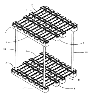
Fig. 6 is a perspective view of a prefabricated
pallet in accordance with the second embodiment of the
present invention. In the second embodiment, the pallet
has a two-storied structure. That is, the pallet
CA 02285248 1999-10-O1
WO 98/45178 PCT/KR98/00077
-11-
according to the second embodiment is formed by arranging
two pallets of Fig. 1 up and down with a plurality of
connection pipes 15 being vertically positioned between
the two pallets.
The upper and lower coupling structures for coupling
the connection pipes 15 to the upper and lower pallets are
shown in Figs. 7a and 7b.
Fig. 7a shows the upper coupling structure for
coupling the top end of each connection pipe 15 to the
upper pallet. As shown in the drawing, the top end of
each connection pipe 15 is fitted into an annular fitting
groove 16, which is defined between the lower portion of
each fitting block part 6 of the vertical member 2 and the
lower portion of each fitting hole 3 of the horizontal
member 1.
Meanwhile, Fig. 7b shows the lower coupling structure
for coupling the lower end of each connection pipe 15 to
the lower pallet. As shown in the drawing, the lower end
of each connection pipe 15 is fitted into a pipe insert
hole 7 of the vertical member 2. The lower end of the
connection pipe 15 has a transverse aperture 15a, so the
connection pipe 15 can be fixed to the pipe insert hole
7 by a coupling rod 13 and is effectively prevented from
an unexpected separation from the pipe insert hole 7.
Z5 The pallet of Fig. 6 has a two-storied structure, so
the pallet supports materials and packages on the upper
and lower pallets, thus enlarging the loading capacity.
Of course, it should be understood that such a many-
- . storied pallet of this invention is not limited to the
two-storied structure but may have three or more-storied
structure. In addition, the number of connection pipes
15, provided between the upper and lower pallets, may be
freely changed in accordance with weight of materials and
CA 02285248 1999-10-O1
WO 98/45178 PCTIKR98/00077
-12-
packages supported by the upper pallet.
The many-storied pallet of Fig. 6 also may be
provided with four side walls, which are fitted in and
held by the grooves of the outermost horizontal and
vertical members 1 and 2 of the upper and lower pallets,
thus being formed as a box-shaped pallet. Such a box-
shaped pallet almost completely covers materials and
packages, thus effectively protecting them from the
outside.
Industrial Applicability
As described above, the present invention provides
a prefabricated pallet, which comprises a plurality of
vertical and horizontal plastic members and is easily and
firmly assembled by fitting the vertical and horizontal
members to each other without using any nails, screws or
rivets and is easily disassembled when necessary.
Therefore, the pallet of this invention improves
productivity when it is assembled. When it is necessary
to move the pallets so as to reuse or store the pallets,
the pallets are easily disassembled. Such disassembled
pallets have a reduced volume and are convenient to users
while being moved.
The above pallet also may be freely changed into
various sizes by changing the arrangement of the vertical
and horizontal members, thus effectively supporting
materials or packages regardless of the size and
configuration of the materials or packages. The pallet
also may have a many-storied structure with a plurality
of connection pipes being vertically positioned between
upper and lower pallets , so the pallet has an enlarged
loading capacity.
CA 02285248 1999-10-O1
WO 98/451?8 PCT/KR98I00077
-13-
Another advantage of the pallet of this invention
resides in that the pallet is formed of a plastic material
effectively resisting against moisture, thus being not
wetted different from typical wood pallets even when the
pallets are stored in a wet environment. Therefore, the
pallet of this invention is almost completely prevented
from being deformed or rotted, thus being effectively used
for a lengthy period of time.
Although the preferred embodiments of the present
invention have been disclosed for illustrative purposes,
those skilled in the art will appreciate that various
modifications, additions and substitutions are possible,
without departing from the scope and spirit of the
invention as disclosed in the accompanying claims.