Language selection

Search

Patent 2285286 Summary

Third-party information liability

Some of the information on this Web page has been provided by external sources. The Government of Canada is not responsible for the accuracy, reliability or currency of the information supplied by external sources. Users wishing to rely upon this information should consult directly with the source of the information. Content provided by external sources is not subject to official languages, privacy and accessibility requirements.

Claims and Abstract availability

Any discrepancies in the text and image of the Claims and Abstract are due to differing posting times. Text of the Claims and Abstract are posted:

  • At the time the application is open to public inspection;
  • At the time of issue of the patent (grant).
(12) Patent: (11) CA 2285286
(54) English Title: GAS TURBINE FOR COMBINED CYCLE POWER PLANT
(54) French Title: TURBINE A GAZ POUR CENTRALE A CYCLE MIXTE
Status: Deemed expired
Bibliographic Data
(51) International Patent Classification (IPC):
  • F02C 6/18 (2006.01)
  • F01D 5/18 (2006.01)
  • F01K 23/10 (2006.01)
  • F02C 7/18 (2006.01)
(72) Inventors :
  • MATSUURA, MASAAKI (Japan)
  • SUENAGA, KIYOSHI (Japan)
  • UEMATSU, KAZUO (Japan)
(73) Owners :
  • MITSUBISHI HEAVY INDUSTRIES, LTD. (Not Available)
(71) Applicants :
  • MITSUBISHI HEAVY INDUSTRIES, LTD. (Japan)
(74) Agent: MARKS & CLERK
(74) Associate agent:
(45) Issued: 2005-01-11
(86) PCT Filing Date: 1998-02-03
(87) Open to Public Inspection: 1999-08-12
Examination requested: 1999-10-01
Availability of licence: N/A
(25) Language of filing: English

Patent Cooperation Treaty (PCT): Yes
(86) PCT Filing Number: PCT/JP1998/000434
(87) International Publication Number: WO1999/040305
(85) National Entry: 1999-10-01

(30) Application Priority Data: None

Abstracts

English Abstract


In a gas turbine for a combined-cycle power plant wherein steam for cooling is
generated in an exhaust-heat recovery boiler to which exhaust gas of a gas
turbine is
supplied, and stationary blades are cooled by the steam for cooling, a cooling-
steam
system is provided by connecting a cooling-steam supply pipe from an exhaust-
heat
recovery boiler to a cooling path formed in a first-stage stationary blade,
providing a
cooling-steam recovery pipe connecting the steam turbine to the cooling path
formed in a
second-stage stationary blade, and providing a connecting pipe for cooling-
steam which
has a relatively large cross-sectional area and connects the cooling paths in
the first-stage
and second-stage stationary blades.


French Abstract

L'invention concerne un système à vapeur de refroidissement dans une turbine à gaz, destiné à une centrale à cycle mixte. Ce système permet de produire de la vapeur de refroidissement dans une chaudière à vapeur de récupération de chaleur, dans laquelle on introduit du gaz d'échappement de la turbine à gaz, et on refroidit des aubes fixes à la vapeur de refroidissement. Ce système comporte une conduite (55) d'amenée de vapeur de refroidissement, en provenance de la chaudière à vapeur de refroidissement, qui communique avec un passage (46) de refroidissement formé dans une aube fixe (39) de premier étage, une conduite (37) de récupération de vapeur de refroidissement, en communication avec une turbine à gaz, qui communique avec un passage (49) de refroidissement formé dans une aube fixe (41) de second étage, et une conduite (47) de raccordement destinée à la vapeur de refroidissement et comportant une surface de coupe relativement grande, qui raccorde, l'un à l'autre, les passages de refroidissement (46, 49) dans les aubes fixes (39, 41) des premier et second étages.

Claims

Note: Claims are shown in the official language in which they were submitted.


5
The embodiments of the invention in which an exclusive property or privilege
is
claimed are defined as follows:
1. A gas turbine for a combined-cycle power plant having an exhaust-heat
recovery
boiler, to which exhaust gas from a gas turbine is supplied and which
generates steam for
cooling, and a stationary blade cooled by the steam for cooling, the gas
turbine
comprising:
a cooling-steam supply pipe, from the exhaust-heat recovery boiler, connected
to a
cooling path formed in a first-stage stationary blade;
a cooling-steam recovery pipe, communicating with a steam turbine, connected
to a
cooling path formed in a second-stage stationary blade; and
a cooling-steam connecting path, having a cross-sectional area larger than
that of the
cooling-steam supply pipe and larger than that of the cooling-steam recovery
pipe,
connecting those cooling paths formed in the first and second-stage stationary
blades.

Description

Note: Descriptions are shown in the official language in which they were submitted.


CA 02285286 2001-11-16
1
GAS TURBINE FOR C',OMBINED-CYCLE POWER PLANT
The present invention relates to a gas turbine, especially for a combined-
cycle
power plant.
In a gas turbine, a steam cooling system has been proposed in which blades are
cooled by steam in proportion as an inlet temperature of high-temperature
combustion
gas increases. In a combined-cycle power plant comprising an exhaust-heat
recovery
boiler in which exhaust gas from the gas turbine is used as a heat source, the
following
steps have been proposed to improve the thermal efficiency of the gas turbine
and the
combined efficiency of the plant: generating low-temperature steam for
cooling, using
the low-temperature steam in the gas turbine for cooling a turbine blade,
using the heated
cooling-steam in a steam turbine, and recovering the thermal energy. An
example of
such a conventional steam cooling stmcture of a gas turbine blade is shown in
Fig. 3.
Cooling paths 5 and 7 are formed inside of a first-stage stationary blade 1
and a
second-stage stationary blade 3 respectively, which are respectively connected
to heads 9
and 11, and those heads 9 and I 1 are connected to independent cooling-steam
supply
pipes 13 and 15, and cooling-steam recovery pipes 17 and 19. Those cooling-
steam
supply pipes 13 and 1 S are connected to an exhaust-heat recovery boiler (not
shown in
Fig. 3) and the cooling-steam recovery pipes 17 and 19 are connected to the
low pressure
turbine of the steam turbine via a separate type superheater.
Furthermore, it has been proposed that the cooling-steam flow in series with
the
cooling paths formed in each stage's turbine blades (Japanese Patent
Application, Second
Publication, No. Sho 63-40244).
As aforementioned, in a steam cooling system in which the cooling-steam
flowing
in parallel to each stage's stationary blades of the gas turbine in the steam
turbine of the
plant, is recovered, and also flows into the steam turbine, the above-
mentioned separate
type superheater is required in order to regulate the condition of the cooling-
steam.
Therefore, the power plant is complicated in structure, large, and its total
cost is high.


CA 02285286 2004-02-05
2
Furthermore, when cooling-steam flows in series to each stage's stationary
blades of the gas turbine in the steam turbine, the whole structure of the
power plant is
complicated, and the pressure drop due to the flow becomes large, so that heat
recovery efficiency in the steam turbine tends to decrease.
In view of the aforementioned, an object of the present invention to provide a
gas turbine for a combined-cycle power plant wherein the cooling-steam used
for heat
recovery has a small pressure drop and a special apparatus such as a
superheater or the
like fpr a steam turbine is not required.
To achieve the above object, the present invention provides a gas turbine for
a
combined-cycle power plant.comprising a steam cooled system having a gas
turbine
for generating steam for cooling in an exhaust-heat recovery boiler to which
exhaust
gas from the gas turbine is supplied, and cooling the stationary blades with
the steam
for cooling,The steam cooling system is constituted by connecting a cooling-
steam
supply pipe from the exhaust-heat recovery boiler to a cooling path formed in
a first-
stage stationary blade, providing a cooling-steam recovery pipe connecting a
steam
turbine to a cooling path formed in a second-stage stationary blade, and
providing a
cooling-steam connecting path having a cross-sectional area larger than that
of the
cooling-steam supply pipe and larger than that of the cooling-steam recovery
pipe, to
connect those cooling paths formed in the above first-stage and second-stage
stationary blades.
The gas turbine for the combined-cycle power plant of the present invention
generates the steam for cooling in the exhaust-heat recovery boiler to which
the
exhaust gas from the gas turbine is supplied, and cools the stationary blades
with that
steam for cooling. A cooling-steam recovery pipe from the aforesaid exhaust-
heat
recovery boiler is connected to a cooling path formed in the first-stage
stationary
blade; a cooling-steam recovery pipe connects the steam turbine to the cooling
path
formed in a second-stage stationary blade; and a cooling-steam connecting
path, which
has a relatively large cross-sectional area, is formed to connect the cooling
paths
formed in the first-stage and second-stage stationary blades. Thus the steam
for
cooling, which has passed through the cooling paths in the first-stage and
second-stage
stationary blades, can be continuously used in the steam turbine as steam for
cooling
because the above steam for cooling has a suitable temperature to drive a
medium-
pressure turbine of the steam turbine, and also the cooling-steam connecting
path
has a relatively large cross-sectional area, so that the pressure drop is as a


CA 02285286 1999-10-O1
3
whole small. Therefore, since no special apparatus such as a heating apparatus
is required,
and the steam for cooling is recovered and used, an increase in manufacturing
cost can be
avoided and also the combined efficiency of the combined cycle power plant can
be
improved.
Brief Description of Drawings
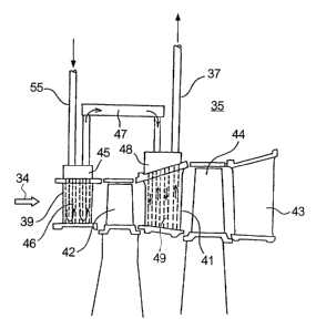
Fig. l is a conceptual system diagram showing the prominent features of one
embodiment according to the present invention.
Fig.2 is a system diagram of the combined cycle power of the embodiment
according to the present invention.
Fig.3 is a conceptual system diagram showing an embodiment of a steam cooling
system in a conventional gas turbine blade.
Best Mode for Carrying Out the Invention
The embodiment of the present invention is explained by referring to the
drawings
as follows.
A system of a combined cycle power plant 20 is explained by referring to
Fig. 2. The gas turbine 30 comprises a compressor 31, a combustor 33, and a
turbine part
35, wherein the compressor 31 compresses air, the compressed air is burned by
blowing fuel
in the combustor 33, a rotor is driven by supplying a high temperature
combustion gas to the
turbine part 35, and finally, electrical energy is extracted by driving a
generator 63.
Exhaust gas in the gas turbine 30 is supplied to an exhaust heat recovery
boiler S0, high-
pressure steam and medium-pressure steam are respectively generated in a high-
pressure
evaporator 51 and a medium-pressure evaporator 53, and those two types of
steam are
supplied to, for example, a two-stage steam turbine 61 to drive it, and
finally, electrical
energy is extracted by driving a generator 63. Then, a part of the medium-
pressure steam is
used for cooling the combustor 33 and a part of the high-pressure steam is
supplied as steam
for cooling to the turbine part 35 of the gas turbine :30 via the cooling
steam supply pipe 55.
Furthermore, the steam for cooling heated by using for cooling is supplied the
steam turbine
61 via the cooling steam recovery pipe 37 and used for driving the turbine.
In Fig. 1, the structure of the steam cooling; system of the turbine part 35
is
conceptually shown. In Fig. 1, a first stage stationary blade 39, a second
stage stationary
blade 41, and a third stage stationary blade 43 are pn~ovided as stationary
blades and their


CA 02285286 1999-10-O1
4
blade parts are set in the direction of the circumference of the stationary
blades. Moreover,
a first stage moving blade 42 behind the first stage stationary blade 39 and a
second stage
moving blade 44 behind the second stage stationary blade 41 are provided as
moving blades,
and the high temperature combustion gas, as shown by arrow 34, flows through
each stage of
blade rows and rotates by driving moving blades 42 and 44. The cooling steam
supply pipe
SS is connected to a junction 45 of the first stage stationary blade 39, and
its steam flowing
path is connected to a cooling path 46 in the first stage stationary blade 39.
The junction 45
of the first stage stationary blade 39 is connected to a junction 48 of the
second stage
stationary blade 41 via a connecting pipe 47, its ste~un path is connected to
a cooling path 49
in the second stage stationary blade 41, and finally, the steam path is
connected to the
cooling steam recovery pipe 37. Further, the cross-sectional area of the
cooling steam
connecting path of the connecting pipe 47 is set to be larger than the other
parts.
In the gas turbine 30 comprising the constituents mentioned above, the first
stage
stationary blade 39, the second stage stationary blade 41, the third stage
stationary blade 43,
etc., tend to undergo increases in temperature because of the high temperature
combustion
gas which flows into the blades contacts and heats the blades. A part of the
high-
temperature steam generated in the high-pressure evaporator 51 in the exhaust
heat recovery
boiler 50 works as steam for cooling and flows into the turbine part 35
through the cooling
steam supply pipe 55. The steam maintains its terr~perature, for example,
350°C, at a part
of the junction 45 (the inlet of the first stage statiomuy blade 39), and
cools the inside of the
first stage stationary blade 39 by flowing through the cooling path 46. The
metal in the
first stage stationary blade 39 is maintained at, for example, 850°C or
less by the above
cooling. The steam outflowing through the connecting pipe 47 is maintained at
approximately 450°C and cools the inside of the second stage stationary
blade 41 by flowing
in the cooling path 49 via the path in the branched assembly 48. As mentioned
above, the
steam for cooling is heated to, for example, approximately 560°C, and
sent to the steam
turbine 61 through the cooling steam recovery pipe :37, and used as steam for
driving the
turbine.

Representative Drawing
A single figure which represents the drawing illustrating the invention.
Administrative Status

For a clearer understanding of the status of the application/patent presented on this page, the site Disclaimer , as well as the definitions for Patent , Administrative Status , Maintenance Fee  and Payment History  should be consulted.

Administrative Status

Title Date
Forecasted Issue Date 2005-01-11
(86) PCT Filing Date 1998-02-03
(87) PCT Publication Date 1999-08-12
(85) National Entry 1999-10-01
Examination Requested 1999-10-01
(45) Issued 2005-01-11
Deemed Expired 2014-02-04

Abandonment History

There is no abandonment history.

Payment History

Fee Type Anniversary Year Due Date Amount Paid Paid Date
Request for Examination $400.00 1999-10-01
Registration of a document - section 124 $100.00 1999-10-01
Application Fee $300.00 1999-10-01
Maintenance Fee - Application - New Act 2 2000-02-03 $100.00 1999-12-22
Maintenance Fee - Application - New Act 3 2001-02-05 $100.00 2001-01-02
Maintenance Fee - Application - New Act 4 2002-02-04 $100.00 2002-01-15
Maintenance Fee - Application - New Act 5 2003-02-03 $150.00 2003-01-14
Maintenance Fee - Application - New Act 6 2004-02-03 $150.00 2003-12-17
Final Fee $300.00 2004-10-25
Maintenance Fee - Patent - New Act 7 2005-02-03 $200.00 2005-01-06
Maintenance Fee - Patent - New Act 8 2006-02-03 $200.00 2006-01-05
Maintenance Fee - Patent - New Act 9 2007-02-05 $200.00 2007-01-08
Maintenance Fee - Patent - New Act 10 2008-02-04 $250.00 2008-01-07
Maintenance Fee - Patent - New Act 11 2009-02-03 $250.00 2009-01-13
Maintenance Fee - Patent - New Act 12 2010-02-03 $250.00 2010-01-13
Maintenance Fee - Patent - New Act 13 2011-02-03 $250.00 2011-01-24
Maintenance Fee - Patent - New Act 14 2012-02-03 $250.00 2012-01-16
Owners on Record

Note: Records showing the ownership history in alphabetical order.

Current Owners on Record
MITSUBISHI HEAVY INDUSTRIES, LTD.
Past Owners on Record
MATSUURA, MASAAKI
SUENAGA, KIYOSHI
UEMATSU, KAZUO
Past Owners that do not appear in the "Owners on Record" listing will appear in other documentation within the application.
Documents

To view selected files, please enter reCAPTCHA code :


To view images, click a link in the Document Description column. To download the documents, select one or more checkboxes in the first column and then click the "Download Selected in PDF format (Zip Archive)" or the "Download Selected as Single PDF" button.

List of published and non-published patent-specific documents on the CPD .

If you have any difficulty accessing content, you can call the Client Service Centre at 1-866-997-1936 or send them an e-mail at CIPO Client Service Centre.


Document
Description 
Date
(yyyy-mm-dd) 
Number of pages   Size of Image (KB) 
Cover Page 1999-11-22 1 56
Claims 2002-08-19 1 24
Representative Drawing 1999-11-22 1 6
Abstract 1999-10-01 1 19
Description 1999-10-01 4 220
Claims 1999-10-01 1 17
Drawings 1999-10-01 3 32
Abstract 2001-11-16 1 18
Drawings 2001-11-16 3 32
Claims 2001-11-16 1 23
Description 2001-11-16 4 221
Description 2004-02-05 4 221
Claims 2004-02-05 1 23
Representative Drawing 2004-04-29 1 7
Cover Page 2004-12-08 1 40
Prosecution-Amendment 2004-02-05 4 124
Assignment 1999-10-01 3 145
PCT 1999-10-01 4 168
Prosecution-Amendment 2001-05-16 2 51
Prosecution-Amendment 2001-11-16 8 259
Prosecution-Amendment 2002-02-20 2 46
Prosecution-Amendment 2002-08-19 3 100
Prosecution-Amendment 2003-01-03 2 60
Prosecution-Amendment 2003-06-25 3 88
Prosecution-Amendment 2003-08-11 1 27
Correspondence 2004-10-25 1 30