Note: Descriptions are shown in the official language in which they were submitted.
CA 02285288 1999-09-27
TWO 98143723 PCT/US98106012
FILTER CARTRIDGE AND FILTER ARRANGEMENT
Background of the Invention
1. Field of the Invention
This invention relates to a filter cartridge capable of being used with a
detachable core and to a filter arrangement using such a filter cartridge.
2. Description of the Related Art
Many filter cartridges are equipped with an internal support member,
generally referred to as a core, for increasing the physical strength of the
filter
cartridge. The core can serve a variety of functions. It can provide the
filter
cartridge with resistance against axial, bending, or torsional loads, and it
can prevent
the filter cartridge from collapsing inwardly under radially inward forces
when the
fluid pressure is greater on the exterior than on the interior of the filter
cartridge.
The core can also be used as a structure for connecting the filter cartridge
to other
members, such as a tube sheet or fitting within a housing.
i5 In many filter cartridges, the core is permanently attached to other
portions of
the filter cartridge, such as to end caps of the filter cartridge. However,
when the
filter medium employed in the filter cartridge is intended to be discarded
when it
becomes loaded with contaminants, it is advantageous to form the filter
camidge such
that the core is readily detachable from the remainder of the filter
cartridge, enabling
the core to be reused as part of another filter cartridge or separately
disposed.
Making the core detachable from the remainder of the filter cartridge not only
decreases waste when the remainder of the filter cartridge is discarded, but
it enables
the filter cartridge to be manufactured more economically and decreases the
weight of
the filter cartridge. For strength purposes, it is frequently desirable to
make the core
of a filter cartridge of metal even though other portions of the filter
cartridge may be
nonmetallic. If a metal core is a permanent part of a filter cartridge, it may
be
impossible to dispose of the filter cartridge by incineration. On the other
hand, if a
metal core is detachable from a filter cartridge, the nonmetallic components
of the
filter cartridge may be disposed of by incineration while the metal core is
reused,
-1-
CA 02285288 1999-09-27
~VVO 98/43723 PCT/US98/06012
providing a significant decrease in the cost of disposing of the used filter
cartridge.
Summary of the Invention
The present invention provides a filter cartridge which is simple in structure
and economical to manufacture and which is without a permanent core but which
is
capable of being used with a detachable core.
The present invention also provides a filter arrangement employing such a
filter cartridge.
The term "filter cartridge" refers to a device including a filter medium which
can he installed as a pre-assembled, replaceable unit in a filter housing or
other part
of a fluid handling system. A filter cartridge according to the present
invention will
generally not include a core as a permanent part of the filter cartridge, but
preferably
it is possible to employ the filter cartridge with a detachable core formed
separately
from the filter cartridge.
According to one form of the present invention, a filter cartridge includes a
filter body having first and second ends, the filter body containing a filter
medium
and having a bore for receiving a core extending to the first end of the
filter body,
and a first end cap adjoining the first end of the filter body. The exterior
surface of
the first end cap has a sealing surface against which a seal to seal the first
end cap to
a portion of a fluid system. In a preferred embodiment, the filter cartridge
includes a
sealing member mounted on the sealing surface for sealing against a filter
housing.
The filter cartridge may also include a second end cap adjoining the second
end of the
filter body.
According to another form of the present invention, a filter arrangement
includes a filter cartridge disposed in a housing. The filter cartridge
includes a filter
body having first and second ends and a first end cap adjoining the first end
of the
filter body. A core for transporting fluid between a bore formed in the filter
body
and an exterior of the filter camidge is removably disposed inside the bore of
the
filter body. The core may be secured to the housing so that the filter
cartridge may
be removed from the housing without removing the core. The core need not be
sealed to either the housing or the filter cartridge. In a preferred
embodiment, a seal
is formed between the interior of the housing and an exterior surface of the
first end
cap.
-2-
CA 02285288 1999-09-27
~VVO 98/43723 PCTIUS98106012
According to yet another form of the present invention, a filter arrangement
includes a filter body having a filter medium and a bore communicating with an
end
surface of the filter body. A first end cap adjoining the end surface of the
filter body
has a sealing surface on an exterior thereof against which a seal can be
formed. A
core is slidably received within the bore of the filter body and has an outer
diameter
enabling the core to pass in a lengthwise direction through a bore in the
first end cap.
Because a seal between a filter cartridge according to the present invention
and
a portion of a filter housing or other component in a fluid system is formed
on an
exterior surface of a first end cap of the filter cartridge, the filter
cartridge is
economical to manufacture. For example, if the first end cap is a molded
member,
the sealing surface of the first end cap may comprise a groove for receiving a
sealing
ring formed on the exterior of the first end cap as part of the molding
process.
Therefore, costly procedures such as machining of the fast end cap to form the
sealing surface can be avoided.
A filter cartridge according to the present invention can be installed
anywhere
along a flow path of a fluid to be treated in a variety of fluid systems. For
example,
it can be installed in a housing, on the exterior of a conduit, or on a wall
or other
surface. It can be used for a variety of types of fluid processing, such as
for
filtration to remove solids from a fluid, for coalescing, for sparging, or for
other
purposes. The filter cartridge is not restricted to use with any particular
fluid and can
be used with liquids, gases, and multiphase mixtures, for example.
Brief Description of the Drawines
Figures 1 through 3 are cross-sectional elevations of different embodiments of
filter arrangements according to the present invention.
Description of Preferred Embodiments
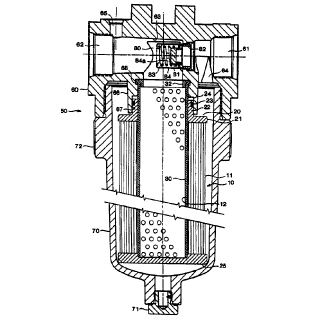
Figure 1 is a cross-sectional elevation of an embodiment of a filter
arrangement employing a replaceable filter carrzidge 10 according to the
present
invention. The filter cartridge 10 is shown disposed in a filter housing 50
surrounding a core 30 detachably connected to the housing 50. The housing 50
includes a head 60 to which the filter cartridge 10 is attached and a bowl 70
which
surrounds the filter cartridge 10 and which is detachably connected to the
head 60 to
-3-
CA 02285288 1999-09-27
WO 98143723 PCTIUS98/06012
enable the filter cartridge 10 to be installed and replaced.
The filter cartridge 10 includes a filter body 11 containing a filter medium,
a
first or upper end cap 20 disposed at one end of the filter body lI, and a
second or
lower end cap 25 disposed at the opposite end of the filter body 11.
While the filter cartridge 10 is shown vertically oriented in the figures with
the
upper end cap 20 disposed above the lower end cap 25, the filter cartridge 10
may
have any desired orientation with respect to the vertical. For example, it may
be
horizontal, or it may be disposed with the first end cap 20 lower than the
second end
cap 25.
The flow path through the filter cartridge 10 during filtration is not
restricted
to any particular direction. For example, the flow path may extend in a radial
direction of the filter cartridge 10 {either radially inwardly or outwardly),
in an axial
direction, or both radially and axially. In the illustrated embodiment, the
fluid to be
filtered normally flows radially inwardly through the filter cartridge 10 from
the
interior of the bowl 70 into the hollow core 30 at the center of the filter
cartridge 10
and out of the housing 50 through the head 60 of the housing 50. Fluid may
also
pass through the filter cartridge 10 in the opposite direction from the normal
flow
direction, such as if the filter cartridge 10 is being cleaned by
baclcwashing.
The filter body 11 is a hollow member containing a filter medium for
performing a desired type of fluid treatment, such as removing selected
materials
from the fluid being filtered, coalescing, or sparging. The overall shape of
the filter
body 11 is not restricted. In the present embodiment, it has an overall
cylindrical
shape on both its inner periphery and its outer periphery, but the peripheries
need not
be cylindrical and need not be of the same shape. For example, one of the
inner and
outer peripheries may be cylindrical while the other of the peripheries is
prismatic,
i.e., polygonal in cross section. The transverse cross section of the filter
body 11
may be constant or may vary over the length of the filter body 11. In the
presem
embodiment, the filter body 11 has a centrally located cylindrical bore 12
which
extends over the entire length of the filter body I1, but the bore i2 need not
be at the
center of the filter body 11 and it need not extend to the bottom end of the
filter body
11. The diameter of the bore I2 may vary in accordance with the desired
tightness of
fit between the filter body 11 and the core 30. It may be desirable for the
bore 12 to
contact the outer surface of the core 30 around the entire circumference of
the core
-4-
..r . , ,, .
CA 02285288 1999-09-27
~VVO 98/43723 PCTIUS98/06012
30 and over substantially the entire length of the filter body lI, since
contact between
the two surfaces can increase the life span of the filter body by preventing
flexing of
the filter body in response to pressure fluctuations which can weaken the
filter body
' over time. In the present embodiment, there is an interference fit between
the bore
S 12 and the core 30 to ensure contact between the opposing surfaces of the
two
members. However, there may instead be a loose fit between the core 30 and the
bore 12, such as a clearance fit.
The structure of the filter body 11 is not restricted. For example, it may
comprise a pleated structure with lengthwise or accordion pleats, it may be a
non-
pleated structure such as a bag filter or a fibrous tube, or it may comprise a
plurality
of sections having different structures. When the filter body 11 has
lengthwise pleats,
the pleats may extend substantially radially with respect to the longitudinal
axis of the
filter body 11, i.e., with the inner and outer ends of each pleat lying
roughly on the
same radius, or the pleats may be in a laid-over state in which the radially
outer end
of each pleat is displaced in the circumferentiai direction of the filter body
11 with
respect to the radially inner end of the pleat as described, for example, in
U.S. Patent
No. 5,543,047.
The filter medium in the filter body 11 may be configured in a variety of
ways. For example, it may be in the form of a mass of fibers, fibrous mats,
woven
or non-woven fibrous sheets, porous membranes such as supported or unsupported
microporous membranes, porous foam, and porous metals or ceramics.
In addition to a filter medium, the filter body 11 may contain a variety of
other components, such as drainage layers, diffusion layers, cushioning layers
for
reducing abrasion of the filter medium, an outer wrap member or sleeve
disposed on
the outer periphery of the filter body I1 to pmtect the filter medium, to
increase the
dirt capacity of the filter body 11, to reduce deformation of the filter body
11 during
pressure fluctuations, to act as a prefilter or support for a filter cake, or
to serve
other purposes. A preferred example of a wrap member is a strip of material
' helically wrapped around the filter body in a plurality of turns with gaps
between
adjoining turns as described, for example, in U.S. Patent No. 5,252,207. When
the
filter body has lengthwise pleats, the wrap member may be joined to the peaks
of the
pleats to restrain movement of the pleats during pressure fluctuations. The
filter body
11 may also include internal support members, such as an inner liner or an
auxiliary
-5-
CA 02285288 1999-09-27
WO 98/43723 PCT/US98/06012
core which is less substantial than the primary core 30 for supporting the
filter body
I1 during its manufacture or handling.
The upper end cap 20 disposed at the end of the filter body 11 adjoining the
head 60 of the housing 50 is an open end cap having a bore through which fluid
can
flow between the head 60 and the interior of the filter body 11. This end cap
20 may
serve a variety of functions. It can be used to seal off the upper end of the
filter
body I1, to physically protect the upper end of the filter body 11, or to
immobilize
the upper end of the filter body 11 against shifting in response to
fluctuations in fluid
pressure. In addition, it seals the filter cartridge 10 to the head 60 of the
housing 50
so that fluid can flow into the head 60 only by passing through the filter
body 11.
The illustrated upper end cap 20 includes a generally disc-shaped base 21
which covers the upper end surface of the filter body 11 and a hollow neck 22
extending outwards from the base 21 and communicating with the interior of the
filter
body 11. The neck 22 may have any desired cross-sectional shape that enables
it to
be connected to the head 60 of the housing 50. Frequently, for ease of
manufacture,
it will have a circular transverse cross section.
The base 21 will typically be sealed to the upper end surface of the filter
body
11 to prevent unfiltered fluid from bypassing the filter body 11. A seal may
be
formed in any manner suited to the materials of which the upper end cap 20 and
the
filter body 11 are formed. For example, sealing may be performed by physically
joining the upper end cap 20 to the filter body I I by a method such as
adhesive
bonding, spin welding, melt sealing, or welding. Alternatively, a seal may be
formed
by a sealing member, such as a gasket, sandwiched between the upper end
surface of
the filter body 11 and the upper end cap 20 and possibly joined to one or both
of the
filter body 11 and the upper end cap 20.
The upper end cap 20 may fit around the core 30 with any desired degree of
tightness, ranging from a clearance fit to an interference fit. As the upper
end cap 20
does not need to be sealed against the core 30, it may be convenient if there
is a
clearance fit between the upper end cap 20 and the core 30 to enable the core
30 to
easily pass through the upper end cap 20. The upper end cap 20 is illustrated
as
having a constant inner diameter, but the inner diameter may vary over the
length of
the end cap 20. For example, the region of the end cap 20 adjoining the filter
body
11 may have a somewhat smaller diameter than the region spaced from the filter
body
-6-
r. .
CA 02285288 1999-09-27
w0 98/43723 PCT/US9810G012
11, thereby reducing manufacturing costs of the end cap 20 because the region
spaced
from the filter body 11 can have looser tolerances than the region of smaller
diameter. Because there is an interference fit between the interior of the
filter body
11 and the core 30 in the present embodiment, when the core 30 is withdrawn
from
the interior of the filter body 11 and the filter body 11 is in a relaxed
state, the filter
body 11 has an inner diameter which is smaller than the minimum inner diameter
of
the upper end cap 20.
The upper end cap 20 is sealed to the head 60 of the housing 50 along a
sealing surface on the exterior of the upper end cap 20. If the upper end cap
20 is
made of a sufficiently resilient material, a seal may be formed by direct
contact
between the upper end cap 20 and the head 60 of the housing 50. More
typically,
however, a seal will be achieved by one or more sealing members, such as O-
rings,
C-rings, or gaskets, formed separately from the upper end cap 20 and mounted
on the
sealing surface of the upper end cap 20. In the illustrated embodiment, the
upper end
i5 cap 20 is equipped with a sealing member comprising an elastomeric O-ring
23
mounted in a circumferentially extending groove 24 formed in the exterior of
the neck
22 of the upper end cap 20, with the interior of the groove 24 comprising a
sealing
surface and being sealed against the O-ring 23. Other possible locations for a
sealing
member are the outer periphery of the base 21 of the upper end cap 20 or on an
axially-facing surface of the upper end cap 20. For example, the sealing
member
may comprise a gasket or a sealing ring mounted on the top surface of the base
21 of
the upper end cap 20, and an axial force may be applied to the filter
cartridge 10 to
compress the sealing member against the surface of the head 60 opposing the
base 21.
The seal produced by the sealing member between the upper end cap 20 and
the housing 50 is of su~cient integrity to prevent substances large enough to
be
captured by the filter body 11 from flowing between the upper end cap 20 and
the
housing 50. Preferably, the sealing member provides a fluid-tight seal under
the
expected operating pressures of the filter arrangement.
Because of the seal between the exterior of the upper end cap 20 and the
housing 50, it is unnecessary to form a seal between the upper end cap 20 and
the
core 30 or between the core 30 and the housing 50. This simplifies the
structure of
the filter arrangement.
Depending upon the loads acting on the filter cartridge 10, it may be
desirable
CA 02285288 1999-09-27
~VVO 98/43723 PCT/US98/Ob012
to secure the upper end cap 20 to the head 60 to prevent the filter cartridge
10 from
becoming detached from the head 60 due to its weight, vibrations, or fluid
pressures
acting in a direction to urge the filter cartridge 10 away from the head 60.
For
example, the upper end cap 20 may be secured to the head 60 by threads, a
bayonet
fit, a clamp, bolts, a snap fit, or frictional engagement. Alternatively, tie
rods or a
spring may maintain the filter cartridge 10 attached to the head 60. In the
present
embodiment, the length of the bowl 70 is such that the filter cartridge 10
cannot be
detached from the head 60 when the bowl 70 is attached to the head 60.
Therefore,
in the present embodiment, the filter cartridge 10 is attached to the head 60
only by
friction between the O-ring 23 and the head 60, and the weight of the filter
cartridge
10 is supported by the head 60 of the housing 50 and/or by the bottom surface
of the
bowl 70.
The upper end cap 20 can be made of any material compatible with the fluid
being filtered, including but not being limited to metals and polymers. The
shape of
the upper end cap 20 makes it particularly convenient to form the upper end
cap 20
by molding, and particularly plastic molding. Since the groove 24 for
receiving the
O-ring 23 is formed in the exterior of the upper end cap 20, the groove 24 can
be
formed as part of the molding process and does not need to be machined, as
would be
an interior groove. Therefore, the upper end cap 20 can be formed quite
economically.
The lower end cap 25 disposed at the end of the filter body l I remote from
the head 60 is not always necessary but is frequently desirable as a means to
seal off
the lower end of the filter body 11, to protect or immobilize the lower end of
the
filter body 1 i , or to connect the lower end of the filter cartridge 10 to
another
member, such as another filter cartridge 10. The illustrated lower end cap 25
is a
blind end cap, but it may instead be an open end cap when, for example, the
filter
cartridge IO is to be connected in series with another member or when the
filter body
I I is of an axial flow type and it is desired to axially introduce fluid to
be filtered
through the Iower end of the filter body 11.
When the bore 12 in the filter body 11 extends to the lower end surface of the
filter body 11, the lower end cap 25 will usually be sealed to the filter body
11.
Sealing may be performed by any of the various methods described with respect
to
the upper end cap 20.
_g_
__ r. ...
CA 02285288 1999-09-27
CVO 98/43723 PCT/US98/06012
Like the upper end cap 20, the lower end cap 25 can be made of any material
compatible with the fluid being filtered and having a strength suitable for
the
functions which the lower end cap 25 is to perform, including but not being
limited to
both metals and plastics. In many cases, it is convenient to form the lower
end cap
25 of a molded plastic.
The core 30 may have any structure which enables it to support the filter body
11 in the desired manner and to transport fluid between the head 60 of the
housing 50
and the interior of the filter body 11. Frequently, the core 30 will be a
tubular -
member having a hollow center and perforations, pores, or other openings in
its
periphery through which fluid can flow between the interior of the core 30 and
the
filter body 11, but the core 30 need not be hollow as long as it is capable of
transporting fluid in a desired direction. For example, the core 30 may be a
solid,
porous member through which fluid can flow axially, or it may be a solid
member
having channels formed in its exterior surface for transporting fluid in the
axial
direction of the core 30. Frequently, the core 30 will be cylindrical, but
other shapes
may be employed, such as a shape with a polygonal or oval cross section, and
the
cross-sectional shape of the core 30 may vary along its length. The core 30
may be
formed of any material compatible with the fluid being filtered and having the
desired
strength, including but not being limited to both metals and plastics. In the
present
embodiment, the core 30 comprises a perforated tube of a corrosion resistant
metal,
such as tin-plated cold-rolled steel.
The core 30 need not extend over the entire length of the filter body 11.
Preferably, it extends over a su~cient region of the length of the filter body
11 to
protect the filter body 11 from damage by radial forces. The upper end of the
core
30 may but need not extend to the exterior of the filter cartridge I0.
Similarly, the
lower end of the core 30 may be disposed entirely within the filter cartridge
10, or if
the lower end cap 25 i'~' an open end cap, the core 30 may extend through the
lower
end cap 25 to its exterior. For example, a core 30 passing through the lower
end cap
25 may be used to support a plurality of filter segments arranged end-to-end
in series.
Furthermore, if the lower end of the core 30 extends through the lower end cap
25,
the core 30 may be used as a tie rod to prevent the filter cartridge 10 from
becoming
detached from the head 60 of the housing 50.
The lower end of the core 30 may be either open or closed, and it may contact
_g_
CA 02285288 1999-09-27
~VVO 98/43723 PCT/US98/06012
or be spaced from the lower end cap 25. For example, if it is desired that the
core
30 resist upward axial forces applied to the filter cartridge 10, the lower
end of the
core 30 may abut against the inner surface of the lower end cap 25. In the
present
embodiment, the length of the core 30 is such that the lower end of the core
30 can
abut against the upper inner surface of the lower end cap 25 without the upper
end
cap 20 abutting against the head 60 of the housing 50 so that when an upwards
force
is applied to the lower end cap 25, the force can be resisted by the core 30
rather
than being applied to the filter body 11.
The illustrated core 30 comprises a single continuous tube, but it is also
possible for the core 30 to be formed from a plurality of sections joined end-
to-end in
series.
If desired, the upper end of the core 30 may be secured to the head 60 of the
housing 50 so as to remain attached to the head 60 when the filter cartridge
10 is
removed from the filter housing 50. The core 30 may be secured to the head 60
in
any convenient manner, either permanently, such as by welding, or detachably,
such
as by threaded engagement or a bayonet fit. In the illustrated embodiment, the
upper
end of the core 30 is retained between the inner periphery of a tubular
fitting 66 of
the head 60 and the outer periphery of a retaining ring 32 disposed in the
fitting 66.
The outer diameter of the retaining ring 32 is small enough for the retaining
ring 32
to be readily inserted into the f fling 66 and abut against a horizontal ledge
of the
fitting 66. The outer diameter of the retaining ring 32 increases from the
lower end
to the upper end of the retaining ring 32. Before being installed on the head
60, the
core 30 in an undefonmed state has a uniform diameter over its entire length.
To
install the core 30 on the head 60, the upper end of the care 30, in its
undeformed
state, is disposed opposite the annular space between the outer periphery of
the
retaining ring 32 and the inner periphery of the fitting 66. An axial
compressive
force is then applied to the core 30 by a suitable mechanism, such as a
hydraulic
press, to force the upper end of the core 30 into the space. For example, the
axial
compressive force can be applied to the lower end of the core 30 while the
fitting 66
is restirained against movement. As the core 30 enters the space, it is
deformed
(possibly elastically but usually plastically) by the expanding outer diameter
of the
retaining ring 32 so as to flare outwards and enter into a groove 68 extending
around
the inner periphery of the fitting 66. When the axial compressive force on the
core
-IO-
, ,..
CA 02285288 1999-09-27
TWO 98/43723 PCTNS98/06012
30 is released, the upper end of the core 30 is retained between the retaining
ring 32
and the groove 68 and is thus secured to the fitting 66 so as to be able to
resist both
tensile and compressive axial forces applied to it. While securing the core 30
to the
head 60 may simplify the installation and replacement of the filter cartridge
10 since
there is no danger of the core 30 falling from the head 60 when the filter
cartridge 10
is removed, it is also possible for the core 30 to loosely engage the head 60
or to be
unconnected to the head 60 so that when the filter camidge 10 is removed from
the
head 60, the core 30 can be removed with the filter cartridge 10. Having the
core 30
readily detachable from the head 60 is convenient when there is insufficient
clearance
beneath the housing bowl 70 to enable the filter cartridge 10 to pass over the
entire
length of the core 30 with the core 30 still attached to the head 60.
The core 30 may be used to support the filter cartridge 10 in a variety of
manners. For example, it may support the filter cartridge 10 against axial
compressive force, against bending or torsional forces, or against radial
forces. The
outer diameter of the core 30 can be selected in accordance with the function
it is
desired that the core 30 perform. As stated above, if the core 30 is intended
to
reinforce the filter body 11 against radially inward forces, the outer surface
of the
core 30 is preferably in contact with or in close proximity to the inner
periphery of
the bore 12 of the filter body 11 so that radially inward deformation of the
filter body
11 will be limited to a level which will not damage the filter body 11. On the
other
hand, if the purpose of the core 30 is simply to help position the filter
cartridge 10
with respect to the filter housing 50 or to resist non-radial forces, the core
30 need
not contact the inner periphery of the filter body 11 at any time.
The core 30 need not be sealed either to the filter cartridge 10 or to the
head
60 since the seal between the upper end cap 20 and the head 60 prevents fluid
from
bypassing the filter body 11. The lack of a need for a seal simplifies the
process of
securing the core 30 to the head 60.
The filter cartridge 10 may include various components other than those
shown in the drawings. For example, it may include a protective cage
surrounding
the filter body 11 and extending between the end caps 20, 25 for protecting
the filter
body 11 from crushing by external forces, for preventing the filter cartridge
10 from
ballooning outwards when subjected to radially outward fluid pressures, or for
providing the filter cartridge 10 as a whole with greater rigidity.
-11-
CA 02285288 1999-09-27
~VVO 98/43723 PCT/US98/06012
An example of a method of forming a filter cartridge according to the present
invention is as follows. The illustrated filter cartridge 10 includes a filter
body 11
formed from a mufti-layer sheet-like composite containing a filter layer, two
drainage
layers each comprising an extruded polymeric mesh on the upstream and
downstream
sides of the filter layer, and a cushioning layer of a highly porous, abrasion
resistant
nonwoven fabric disposed between the filter layer and one or both of the
drainage
layers. The composite is pleated with conventional corrugating equipment to
form
parallel lengthwise pleats, and the pleated composite is formed into a tubular
shape
and sealed in a conventional manner along the lengthwise edges of the
composite to
I0 form a lengthwise side seal. After the side seal is formed, a wrap member
is wound
helically around the exterior of the pleats in a plurality of turns with a
helical gap
between adjoining turns. The wrap member comprises a thin strip of a polymeric
nonwoven fabric which is joined to the radially outer ends of the pleats by a
plurality
of beads of a hot melt adhesive extending along the length of the wrap member
to
maintain the spacing between adjoining pleats. The tension on the wrap member
is
controlled to give the filter body a desired inner diameter. Two polymeric end
caps
20, 25 are then melt sealed to the lengthwise end surfaces of the filter body
11 over
the ends of the wrap member, and a polymeric O-ring 23 is mounted in a
circumferentially-extending groove 24 in the upper end cap 20 to complete the
filter
cartridge 10.
A housing for use with the filter cartridge 10 may have any structure which
enables it to guide fluid to be treated through the filter cartridge 10 in a
desired
direction. The illustrated housing 50 is designed to house a single filter
cartridge 10,
but it may instead have a structure enabling it to house a plurality of filter
cartridges
10. The bowl 70 of the housing 50 may be detachably connected to the head 60
in
any suitable fluid-tight manner, such as by threaded engagement between
external
threads formed at tha~.upper end of the bowl 70 and internal threads formed on
the
head 60. The illustrated bowl 70 is formed with flats 72 on its outer surface
which
make it easier to grasp and turn the bowl 70 when it is being connected to or
disconnected from the head 60. The bowl 70 may also be equipped with a drain
plug
71 in its lower portion. The head 60 includes the above-described hollow
fitting 66
for receiving the neck 22 of the upper end cap 20 of the filter cartridge I0.
The
fitting 66 may have any shape which enables its inner surface to seal against
the
-12-
,, .
CA 02285288 1999-09-27
WO 98/43723 PCT/US98106012
sealing ring 23 on the upper end cap 20. In the present embodiment, the
fitting 66
has a cylindrical inner surface 67 for sealing against the sealing ring 23,
but if the
neck 22 of the upper end cap 20 is noncylindrical, the inner surface 67 may
have a
' similar noncylindrical shape corresponding to that of the neck 22. The
fitting 66 in
the present embodiment is integrally formed with other portions of the head
60, but it
may be a separately formed member, such as a detachable member to enable the
head
60 to be used with different types of filter cartridges by installing a
fitting 66 having
a size and shape corresponding to the filter cartridge which is to be
employed. The
head 60 also includes an inlet 61 and an outlet 62 which open onto exterior
surfaces
of the head 60. A connecting bore 63 is formed through the head 60 between the
inlet 6I and the outlet 62. The inlet 61 communicates through a passage 64
with the
region within the bowl 70 surrounding the filter cartridge 10, while the
outlet 62
communicates with the interior of the fitting 66 through the connecting bore
63. A
spring-loaded bypass valve 80, which may be of conventional design, may be
installed in the connecting bore 63 to fluidly interconnect the inlet 61 and
the outlet
62 when the pressure differential between the inlet 61 and the outlet 62
reaches a
certain level, such as a level which could damage the filter cartridge 10 or
impose an
excessive load on pumping equipment forcing fluid through the filter cartridge
10.
The illustrated bypass valve 80 includes a poppet 81 which can move into and
out of
sealing contact with a hollow valve seat 82 disposed in the connecting bore
63. The
poppet 81 is urged into sealing contact with the valve seat 82 by a biasing
spring 83
disposed in a cage 84 having one or more openings 84a in its periphery through
which fluid can flow between the interior and exterior of the cage 84. One
side of
the poppet 81 (the right side in Figure 1) is exposed to the fluid pressure at
the inlet
61, while the opposite side of the poppet 81 is exposed to the fluid pressure
at the
outlet 62. During normal operating conditions, the difference between the
fluid
pressures at the inlet 61 and the outlet 62 is such that the poppet 81 is
closed so that
all fluid which enters the inlet 61 is directed into the bowl 70 through
passage 64 to
be filtered by the filter cartridge 10. As filtering proceeds and the filter
cartridge 10
accumulates particles present in the fluid being filtered, the pressure
differential
between the inlet 61 and the outlet 62 increases. When the pressure at the
inlet 61
exceeds the pressure at the outlet 62 by more than a predetermined value
indicating
that the filter body 11 has become loaded and needs replacement or cleaning,
the
-13-
CA 02285288 1999-09-27
~VVO 98/43723 PCT/US98/06012
poppet 81 opens against the biasing force of the spring 83 and allows fluid to
bypass
the filter cartridge 10 by flowing from the inlet 61 to the outlet 62 through
the
connecting bore 63. The opening of the poppet 81 equalizes the pressures at
the inlet
61 and the outlet 62 and prevents the filter cartridge 10 or pumping equipment
from
being damaged by too high a differential pressure. Although not shown, the
head 60
may also contain a differential pressure indicator which is subjected to the
inlet and
outlet pressures and which produces an indication, such as an electrical
output signal
or a visual indication, when the differential pressure across the filter
cartridge 10
reaches a predetermined level, such as a level causing the bypass valve 80 to
open.
The head 60 may also include an air vent 65 communicating between the
interior and exterior of the head 60. The air vent 65 can be used to permit
air or
other gas to escape from the interior of the head 60 when the housing 50 is
being
filled with fluid prior to the start of filtering operation. After venting,
the air vent 65
can be closed with an unillustrated plug or other suitable member. The air
vent 65 is
normally kept closed during operation of the filter arrangement.
Although not shown, the head 60 of the housing 50 may include a check valve
disposed between the upper end of the filter cartridge 10 and the outlet 62 to
prevent
fluid from flowing from the outlet 62 into the core 30 when the filter
cartridge 10 is
being removed from the housing 50.
When it is desired to replace the filter cartridge 10, the bowl 70 is
unscrewed
from the head 60 of the housing 50, and the filter cartridge 10 is pulled
downwards
along the core 30 until it is free of the core 30. The filter cartridge 10 can
then be
cleaned, discarded, incinerated, or otherwise disposed of in a suitable
manner. A
replacement filter cartridge 10 is then slid upwards over the core 30 until
the O-ring
23 on the upper end cap 20 of the replacement filter cartridge 10 enters into
the
fitting 66 and seals against the inner surface 67 of the fitting 66. The bowl
70 can
then be reconnected to the head 50 to enable filtering operation to resume.
Figure 2 is a cross-sectional elevation of another embodiment of a filter
arrangement according to the present invention. The filter cartridge 10 in
this
embodiment is identical to that of the previous embodiment, the principle
difference
between this embodiment and the previous embodiment being the structure of the
housing 100 of the filter arrangement. The housing 100 includes a head 110 and
a
bowl 140 detachably mounted on the head I10 for receiving the filter cartridge
10.
-14-
i ~..
CA 02285288 1999-09-27
WO 98143723 PCT/US98106012
The head 110 includes an inlet 111 which opens onto a side surface of the
exterior of
the head 110 and an outlet 114 which opens onto a top surface of the head 110.
The
inlet 111 and the outlet 114 both communicate with an inlet chamber 112 which
opens
onto the bottom surface of the head 110. The bowl 140 of the housing i00 can
be
connected to the bottom surface of the head 110 in any suitable fluid-tight
manner so
as to communicate with the inlet chamber 112. Far example, the Iower end of
the
inlet chamber 112 may be formed with internal threads 113 for threaded
engagement
with external threads formed on the upper end of the bowl 140. A hollow
fitting 120
for receiving the upper end cap 20 of the filter cartridge 10 is mounted in a
connecting bore 115 connecting the inlet chamber 112 and the outlet 114. The
fitting
120 includes a cylindrical base 121 which is screwed into internal threads
formed in
the connecting bore 115 and a tubular portion 123 which extends away from the
base
121 into the inlet chamber 112. The tubular portion 123 has a cylindrical
inner
surface 124 which receives the neck 22 of the upper end cap 20 of the filter
cartridge
10 and is in sealing contact with the sealing ring 23 mounted on the neck 22.
The
core 30 in the present embodiment is secured to the interior of the tubular
portion
i23, but as in the previous embodiment, the core 30 may be loosely received by
the
head 110, or it may be unconnected to the head 110. In the present embodiment,
the
upper end of the core 30 is held between a groove 125 formed around the inner
periphery of the tubular portion 123 of the fitting 120 and the outer surface
of a
retaining ring 136 which performs a function similar to that performed by the
retaining ring 32 of Figure 1. The upper end of the tubular portion 123 of the
fitting
120 also contains a bypass valve 130. The bypass valve 130 includes a hollow
poppet 131 which is slidabiy received in the tubular portion 123 and can slide
between a closed position, shown in Figure 2, in which the upper end of the
poppet
131 is in sealing contact with an annular valve seat 133 disposed at the upper
end of
the connecting bore 115, and an open position in which the poppet 131 is moved
downward from the closed position so that the upper end of the poppet 131 is
spaced
from the valve seat 133 and fluid can flow between the poppet 131 and the
valve seat
133 through a central opening in the valve seat 133 and into the outlet 114. A
sealing member 134 such as a sealing ring may be provided to form a seal
between
the valve seat 133 and the head 110. The poppet 131 is biased toward its
closed
position by a biasing spring 135, one end of which contacts the upper surface
of the
-15-
CA 02285288 1999-09-27
~VVO 98/43723 PCT/US98/06012
retaining ring 136, which also functions as a spring seat, and the other end
of which
is pressed against a ledge formed on the interior of the poppet 131. A sealing
ring
132 may be mounted on the exterior of the poppet 131 to form a sliding seal
between
the poppet 131 and the tubular portion 123 of the fitting 120. The interior of
the
poppet 131 is exposed to fluid at the pressure of the outlet 114, and the
exterior
surface of the poppet 131 above the sealing ring 132 is exposed to the
pressure in the
inlet chamber 112 through one or more passages 122 formed in the base i21 of
the
fitting 120 and extending between the side of the base 121 opposing the inlet
chamber
112 and the side of the base 121 opposing the valve seat 133. The spring force
of the
biasing spring 135 is selected such that under normal filtering conditions in
which the
differential pressure across the filter cartridge 10 is acceptable, the poppet
I3I will
remain closed so that fluid can flow between the inlet chamber 112 and the
outlet 114
only by passing through the filter cartridge 10. However, when the filter
cartridge 10
becomes loaded with particles in the fluid being filtered and the differential
pressure
between the inlet 111 and outlet 114 reaches a predetermined level, the poppet
131
will open by moving downward away from the valve seat 133, thereby allowing
fluid
to bypass the filter cartridge 10 and to flow from the inlet chamber 112 into
the outlet
114 through the bores 122 in the base 121. When the poppet I31 is moved to its
open position, the lower end of the poppet 131 may seat on an annular ledge
137 of
the retaining ring 136 at the lower end of the biasing spring 135.
An unillustrated differential pressure indicator for sensing the pressure
differential between the inlet chamber 112 and the outlet 114 may be inserted
into a
chamber 116 opening onto the exterior of the housing 100. The chamber 116
communicates with the inlet chamber 112 through a first passage l I7 and with
the
outlet 114 through a second passage l I8 so that a differential pressure
indicator
disposed in the chamber 116 can be exposed to both the inlet and outlet
pressures.
The differential pressure indicator may be of any type which generates an
indication,
such as an electrical output signal or a visual indication, when the pressure
in the
inlet chamber 112 exceeds the pressure in the outlet 114 by more than a
predetermined amount, indicating that the filter cartridge i0 needs
replacement.
As stated above, the core 30 does not need to be permanently connected to a
housing or other component of a fluid system. Figure 3 illustrates another
embodiment of a filter arrangement according to the present invention which is
-16-
.,. _ ~, .
CA 02285288 1999-09-27
WO 98!43723 PCT/US98/06012
identical to the embodiment of Figure 1 except that the core 30 is loosely
received in
the fitting 66 of the head 60 of the housing 50 rather than being secured to
it so that
the core 30 and the filter cartridge 10 can be installed on and removed from
the head
60 at the same time.
-17-