Note: Descriptions are shown in the official language in which they were submitted.
CA 02285397 2006-12-29
1
DEVICE FOR CLAMPING THE CABLE IN ELECTRICAL OUTLETS OR PLUGS
FIELD OF THE INVENTION
The present invention pertains to the electrical outlets or plugs for
industrial and/or
tertiary use with a device for clamping the electrical cable in such devices.
BACKGROUND OF THE INVENTION
In general, the electrical outlets or plugs for industrial and/or tertiary use
comprise a
body and a connecting jack. The latter is enclosed in the body and may have
connection openings in the case of an outlet or pins in the case of a plug
that are
turned towards one end of the body. The openings or pins of the jack are then
connected to the corresponding electric wires of a cable, which enter from the
opposite end of the body.
To prevent the detachment of the electric wires from the jack, the cable is
usually
clamped in the body. Up to now, this clamping was carried out using various
systems, but usually with a tie-type clamping cable, i.e., with a band which
is placed
in the body cir is attached to the jack and which is tightened around the
cable by
means of at least one clamping screw.
However, this system is neither easy nor practical to carry out since it
involves the
means inside the body and always requires the use of a tool, such as a
screwdriver,
both for clamping and for releasing.
SUMMARY AND OBJECTS OF THE INVENTION
The primary object of the present invention is to propose a device for
clamping the
cable in electrical outlets or plugs, which is simpler, easier, and is able to
facilitate
the clamping/release of the cable even without the availability of tools.
CA 02285397 2006-12-29
2
Another object of the present invention is to propose a device to clamp the
cable in
electrical outlets or plugs which advantageously uses such parts of the outlet
or plug
body forthe clamping, without, i.e., resorting to additional and complex
components.
Another object is to propose an electrical outlet or plug having a device for
clamping
the cable, which also incorporates means capable of preventing its accidental
release, when the cable is clamped, to prevent an unintentional and
uncontrolled
detachment of the clamping elements when they are in the release position for
the
insertion or removal of the cable in the outlet or plug.
The objects are accomplished, according to the present invention, with a
device for
clamping a cable in an electrical outlet or plug, the device comprising:
a body that encloses a connecting jack for connecting to the cable to be
clamped;
a threaded locking nut;
a grip element which is arranged in the body between the body and the
threaded locking nut on an inlet side of the cable, the grip element including
a
plurality of flexible jaws; and
a conucal connection joining the grip element to the body, the grip element
being tightened around the cable to be clamped after the locking nut is
screwed onto
the body, wherein the grip element is provided with two tongues, which are
parallel to
the jaws and are intended to be inserted and to slide in corresponding
indentations
on an outside of the body, and in which the tongues have lateral locking
teeth, which
are intended to intercept opposing teeth on sides of the indentations in order
to
prevent the detachment of the grip element when the grip element is stopped in
relation to the body, the conical connection including a substantially conical
seat
formed of grooves which are intended to accommodate the flexible jaws of the
grip
element and to prevent rotation of the grip element with the locking nut.
Also, all the elements are advantageously connected axially without cross
components, which especially simplifies their structure and facilitates their
embodiment.
CA 02285397 2006-12-29
-3
The present invention also proposes a device for clamping a cable in an
electrical
outlet or plug, the device comprising:
a body that encloses a connecting jack for connecting to the cable to be
clamped;
a threaded locking nut;
a grip element which is arranged in the body between the body and the
threaded locking nut on an inlet side of the cable;
a conical connection joining the grip element to the body, the grip element
being tightened around the cable to be clamped after the locking nut is
screwed onto
the body;
the body and the grip element are provided with complementary limiting
means to limit axial movement of the body and the grip element and to prevent
disconnection of the body and the grip element once they have been connected
and
the locking nut is unscrewed from the body;
the locking nut and the grip element are joined axially for allowing the nut
to
rotate in relation to the grip element, but to remain joined to the grip
element and,
through this, to the body when the nut is completely unscrewed and removed;
and
the locking nut and the grip element include means which interact to make
possible a unidirectional rotation for screwing and to prevent the opposite
rotation for
unscrewing when the nut is screwed onto the body for clamping the cable with
the
grip element, wherein the grip element is provided with two tongues, which are
parallel to a plurality of flexible jaws and are intended to be inserted and
to slide in
corresponding indentations on an outside of the body, and in which the tongues
have
lateral locking teeth, which are intended to intercept opposing teeth on sides
of the
indentations in order to prevent the detachment of the grip element when the
grip
element is stopped in relation to the body.
The present invention also provides a device for clamping a cable in an
electrical
outlet or plug, the device comprising:
a body that encloses a connecting jack for connecting to the cable to be
clamped;
a threaded locking nut;
CA 02285397 2006-12-29
4
a grip element which is arranged in the body bet+rjeen the body and the
threaded locking nut on an inlet side of the cable;
a conical connection joining the grip element to the body, the grip element
being tightened around the cable to be clamped after the locking nut is
screwed onto
the body; and
a seall placed in the body, the seal including a part that is made in one
piece
with the body proper and acts around the cable, adapting to the cable without
a need
for intervention, wherein the grip element is provided with two tongues, which
are
parallel to a plurality of flexible jaws and are intended to be inserted and
to slide in
correspondirig indentations on an outside of the body, and in which the
tongues have
lateral locking teeth, which are intended to intercept opposing teeth on sides
of the
indentations in order to prevent the detachment of the grip element when the
grip
element is stopped in relation to the body.
The various features of novelty which characterize the invention are pointed
out with
particularity in the claims annexed to and forming a part of this disclosure.
For a
better understanding of the invention, its operating advantages and specific
objects
attained by its uses, reference is made to the accompanying drawings and
descriptive rriatter in which preferred embodiments of the invention are
illustrated.
BRIEF DESCRIPTION OF THE DRAWINGS
In the drawings:
FIG. 1 is a perspective view showing an example of an electrical plug which is
assembled and is attached to a cable.
FIG. 2 is an exploded perspective view of a part of the plug body and the
means for
clamping the cable in a first embodiment.
FIG. 3 is a sectional view of the device of FIG. 2 with the cable in the
clamped state.
FIG. 4 is an exploded perspective view of a part of the body of the outlet or
plug, the
grip element and the locking nut in another embodiment.
CA 02285397 2006-12-29
FIG. 5 is a cross sectional view of the components illustrated in FIG. 4, but
assembled.
FIG. 6 is an axial sectional view of the clamping device but in the release
position, in
which the nut and grip element are in the withdrawn position in relation to
the body,
5 and they remiain, however, joined to this body.
FIG. 7 is an exploded view showing a part of the body of the outlet or plug,
the grip
element and the locking nut in another embodiment.
FIG. 8 is a perspective cut away view showing the connection of the grip
element
with the body of the outlet or plug according to the embodiment of FIG. 7.
FIG. 9 is a perspective view showing components of the outlet or plug of FIG.
7
assembled.
FIG. 10 is a lateral view of all the components of the outlet or plug of FIG.
7
assembled, respectively.
FIG. 11 is a Iongitudinal perspective sectional view of the unit of FIGS. 9
and 10.
DESCRIPTION OF THE PREFERRED EMBODIMENT
Referring to the drawings in particular, the present invention concerns an
electrical
plug, which includes a body or grip 11 and a holding element 12. Grip 11 and
holding
element 12 are joined to one another and enclose a connecting jack, which, in
the
case shown, is shown with the pins 13 (FIG. 1) and is indicated globally as
10. The
electric wires assembled in a cable 14, which enters the body 11 through the
free
end, are conriected to the connecting jack 10.
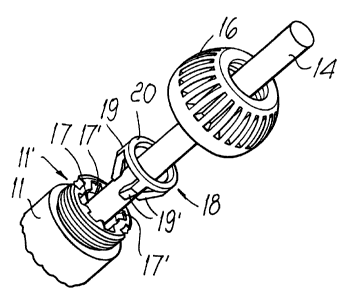
A collar 11', which has, on the outside, a threading 15 on which a locking nut
16 is
screwed and, on the inside, a seat 17 with the conical grooves 17' in the
longitudinal
direction, is provided at this end of the element of the body 11 (see FIG. 2).
CA 02285397 2006-12-29
6
A grip clamp element 18, which has the flgxible jaws 19 that extend from an
annular
portion 20, is mounted between the collar 11' and the nut 16, concentrically
to the
cable 14.
The jaws 19 have at least one conical part 19' and are turned towards the seat
17 in
the collar 11' of the body, fitting into the conical grooves 17'.
On the other hand, the annular portion 20 of the grip element 18 is turned
towards,
and interacts with, an annular striking surface 21, which is provided inside
the nut 16.
Thus, to clamip the cable 14 once the plug (or outlet) has been assembled and
wired,
it is only necessary to screw the nut 16 onto the threaded collar 11' of the
body.
Then, the jaws 19 of the grip element 18, pushed by the nut 16, interact with
the
conical grooves 17' and they are forced to tighten around the cable 14,
clamping it. It
should be noted that the connection of the jaws 19 with the grooves 17' in the
conical
seat 17 prevents the rotation of the grip with the nut during the screwing
down of
same, thus avoiding subjecting the cable to undue twisting.
In the exemplary embodiment of FIGS. 4-6, the body 111 of an electrical outlet
or
plug is shown only partially in its end part, in which it has a collar 111'
with an
external threading 115, onto which a locking nut 116 is screwed. A seat 117
which
has conical (as used herein, slanted so as to generally corresponding to a
conical
shape) grooves 117 in the longitudinal direction is also provided in the body
111, and
a grip element 118 is mounted between the collar 111' and the nut 116 for
clamping
the electric cable, which is passed through there centrally.
Similarly to that described for FIGS. 1-3, the grip element 118 has the
flexible jaws
119 that come from an annular portion 120 and that have a conical portion
119',
which is intended to be joined with the conical grooves 117 in the collar of
the body.
The annular portion 120 of the grip element 118 is turned towards, and
interacts with,
an annular striking surface 121 inside the locking nut 116.
In this embodiment, the grip element 118 is also provided with one or, more
preferably, two diametrically opposed tongues 122, 123, which are parallel to
its jaws
CA 02285397 2006-12-29
7
119 and are intended to be inserted in corresponding indentations 124, 125
provided
on the outside of the body 111. A first tongue 122 may be in the form of an
attachment to the grip element 118, lying halfway between two contiguous jaws
119,
projecting towards the outside of same. The second tongue 123 is in a position
halfway between two contiguous jaws 119, but moved outwardly in relation to
same
and extending from the annular portion 120.
The first tongue 122 is longer than the second tongue 123, and
correspondingly, the
indentation 124 intended to accommodate it is longer than the indentation 125
provided for the other tongue 123, and the longer tongue protrudes from the
opening
of the nut 116.
Two lateral locking teeth 122', 123' are provided on the sides of each tongue
122,
123, respectively.
Two opposing teeth 124', 125', which are turned towards one another, are
provided
on the sides of each indentation 124, 125, close to the free end of the collar
111',
respectively.
The tongues 122, 123 of the grip element 118 (FIGS. 4 and 6) are inserted by
force
into the respective indentations 124, 125 of the body 111, so that the element
may
slide axially in relation to the body.
However, in the direction of unthreading the grip element 118, the lateral
teeth 122',
123' of the tongues 122, 123 strike against the teeth 124', 125' on the sides
of the
indentations 124, 125 so as to stop the element proper, thus preventing its
detachment from the body 111 of the outlet or plug.
On the other hand, even the locking nut 116 remains joined in the axial
direction to
the grip element 118 and, through this, to the body 111 of the outlet or plug.
To this
end, the internal edge of the annular striking surface 121 of the nut 116 is
provided
for being inserted by force into a groove 126, which is present around a
protuberance
of the grip element lying above the annular portion 120 of same. This
connection
then makes possible the rotation of the nut in relation to the grip element
for
screwing and unscrewing onto the threaded section of the collar of the body
111 and,
CA 02285397 2006-12-29
8
as stated above, to keep the nut and grip element joined to one another and to
the
body 111.
Also accordirig to the present invention, a toothed crown 127 is provided
inside the
nut 116, close to its opening, and a stop tooth 128 that is intended to
interact with the
toothing 127 is provided on the outer face of the longer tongue 122.
The stop tooth 128 is so as to make possible the unidirectional rotation from
left to
right of the nut 116 for its screwing onto the threaded collar 111' of the
body 111 and,
on the other hand, to prevent the opposite rotation of the nut for its
unscrewing.
Thus, the nut 116 can be screwed to the boftom for the clamping of the cable
through the grip element, but cannot be loosened and be unscrewed
uncontrollably
due to an unintentional release of the cable. In fact, to unscrew the nut, it
is
necessary to act intentionally using a tool on the tongue 122 in the manner of
pushing it inwards and of keeping the stop tooth 128 disconnected from the
toothing
127 during the unscrewing operation, which thus can only be intentional.
Thus, the nut: 116, once it has been screwed down to clamp the cable by means
of
the grip element, cannot be unscrewed by unclamping the cable in an
uncontrolled
manner, and the nut and grip element remain permanently joined to one another
and
to the body of the outlet or plug.
It should also be noted that a ring seal 129, through which the cable passes
and
which guarantees the sealing around same below the grip element, may be
mounted
inside the body without being affected by the clamping and unclamping means.
In the embodiment of FIGS. 7-11 as well, the body 211 of an electrical outlet
or plug
is shown only partially in its end part, in which it has a collar 211' with an
outer
threaded section 215 onto which a locking nut 216 is screwed. A seat 217,
which has
conical grooves 217' in the longitudinal direction, which are narrowed towards
the
inside of the body, is provided in the body 211.
A grip elemerit 218 is mounted between the collar 211' and the nut 216 for
clamping
the electrical cable, which is passed through there centrally and which
extends
through a seal 229.
CA 02285397 2006-12-29
9
Here as well, the grip element 218 has flexible jaws 219, which come from an
annular portion 220 and which have a conical portion 219' intended to be
joined to
the conical grooves 217' in the collar of the body.
The annular portion 220 of the grip element 218 is also turned towards, and
interacts
with, an annular striking surface 221 inside the nut 216, so that the element
is
pushed into the body when the nut is screwed onto the threaded section 215.
In this case, the grip element 218 is provided with two tongues 222 to limit
the
unthreading of the element proper from the body 211. The tongues 222 are
identical,
diametrically opposite, placed between two contiguous jaws, and moved
outwardly in
relation to same. These tongues 222 are intended to be inserted and to slide
in
corresponding indentations 224 provided on the outside of the collar 211' of
the body
211, corresponding to two flattened sections 223. Each tongue 222 has two
lateral
locking teeth 222' while two opposing steps 224' are provided on the sides of
each
indentation 2;24, close to the free end of the collar 211'.
The tongues 222 of the grip element 218 are inserted in the respective
indentations
224 of the collar 211' so that the element may slide axially in relation to
the body.
However, in tlhe unthreading direction of the grip element 218, the lateral
teeth 222'
of the tongues 222 strike against the steps 224' on the sides of the
indentations 224
so as to stop 'the element proper, thus preventing its detachment from the
body 211
of the outlet or plug.
In addition, the locking nut 216 remains joined in the axial direction to the
grip
element 218 and, through this grip element 218, to the body 211 of the outlet
or plug.
To this end, the internal edge of the annular striking surface 221 of the nut
216 is
provided for being inserted by force into a groove 226, which is present
around a
protuberance of the grip element lying above the annular portion of same, and
this
groove 226 may be defined by a continuous collar or one with sections, as
shown in
the drawings.
The connection then makes possible the rotation of the nut 216 in relation to
the grip
element 218 for screwing and unscrewing on the threaded section 215 of the
collar
CA 02285397 2006-12-29
of the body; however, the nut and grip element are kept joined to one another
and,
through the tongues 222, to the body of the outlet or plug.
According tc> another feature, the outer surface of the nut 216 has a toothing
or
broaching 227, and the body 211, on one side of the collar 211', in the
longitudinal
5 direction, is provided with a lug, which extends above one of the lateral
flattened
sections 223 of the collar 211' and on the outside of the nut 216 when same is
screwed onto the collar proper. A stop tooth 228' (FIGS. 7-9), which is
intended to
engage with the outer toothing or broaching 227 of the nut 216, is provided on
the
internal surface of the lug 228.
10 The stop tooth 228' of the lug 228 is so as to make possible the
unidirectional
rotation (from left to right) of the nut for its screwing onto the threaded
collar 211' of
the body 211 and, on the other hand, to prevent the opposite rotation of the
nut for
its unscrewing. Therefore, the nut 216 can be screwed to the bottom for
clamping the
cable through the grip element, but it cannot be loosened and unscrewed in an
uncontrolled manner due to an unintentional release of the cable.
In fact, to unscrew the nut, it is necessary to act intentionally using a tool
on the lug
228 in the manner of moving it away from the nut to disconnect its stop tooth
228'
from the outer toothing 227 of the nut during the unscrewing operation, which,
thus,
can only be intentional.
While specific embodiments of the invention have been shown and described in
detail to illustrate the application of the principles of the invention, it
will be
understood that the invention may be embodied otherwise without departing from
such principles.