Note: Descriptions are shown in the official language in which they were submitted.
CA 02285422 1999-10-O1
WO 98!48231 PCT/EP98l02012
1
COOLER FOR PARTICULATE MATERIAL
The present invention relates to a cooler for cooling
particulate material which has been subjected to heat
treatment in an industrial kiln, such as a rotary kiln for
manufacturing cement clinker, which cooler comprises an
inlet, an outlet, end walls, side walls, a bottom and~a
ceiling, at least one stationary supporting surface for
receiving and supporting the material to be cooled, means
l0 for injecting cooling gas into the material, as well as a
reciprocating scraper system which comprises a number of
rows of scraper elements which extend transversely across
the direction of movement of the material, said elements
being moved back and forth in the direction of movement of
the material in order to convey the material forward over
the supporting surface.
In EP 0718578 a cooler of the aforementioned kind is
described. In this known cooler, the scraper elements are
made up of cross bars with a triangular cross-sectional
profile, with the bars being mutually connected via chains
and being moved back and forth on the supporting surface by
means of chain wheels f fitted at the ends of the supporting
surface. This known cooler has several drawbacks. Because
of the high temperatures which occur in the cooler, and
particularly at the inlet end of the cooler, as well as the
substantial forces which are required to convey the
material through the cooler, the chains must be designed
with relatively large dimensions. As a result, the chains
will form so-called shadow areas of equivalent size, i.e.
areas in which the chains obstruct the upward-flowing
cooling gas so that the overlying material is not cooled as
intended. Also, the cross bars in the known cooler are not
firmly fixed to restrain them from moving, neither
perpendicularly to the material's direction of movement nor
in terms of rotation about their own longitudinal axis. In
cases where a larger body of material is to be conveyed
through the cooler, one or several cross bars may therefore
CA 02285422 1999-10-O1
WO 98/48231 PCTIEP98/02012
2
be forced vertically upwards, and may come to ride on the
body. This will reduce the conveyance of material through
the cooler. In cases where a cross bar is lifted at one
side only, the cross bar will also be able to move towards
one side of the cooler, thereby giving rise to operational
disorders. Rotation of one or several of the cross bars may
have an adverse effect on the efficiency of conveyance.
Furthermore, the known cooler is vulnerable to operational
disorders, for example in event of rupture of a single
chain link, given the necessity to shut down the cooler in
order to undertake the necessary repair work. A further
disadvantage of the known cooler is that the driving system
in the form of the chains consists of wear parts which must
be replaced at regular intervals.
The purpose of the present invention is to provide a
cooler by means of which the aforementioned disadvantages
are eliminated.
This is achieved by means of a cooler of the kind
mentioned in the introduction, and being characterized in
that each row of the transverse scraper elements is firmly
f fixed to at least one drive plate oriented in the direction
of movement of the material, and in that said drive plate
extends at least across the entire length of the supporting
surface, and in that said drive plate is led either through
the supporting surface, the ceiling, one of the side walls
and/or at least one of the end walls of the cooler, where
the drive plate is connected to a drive arrangement for
movement back and forth.
Hereby is obtained a better and more uniform cooling
of the material in the cooler, a better and safer
conveyance of the material through the cooler, a higher
degree of operational reliability and a reduction of the .
wear to which the drive elements are exposed. The cooling
of the material is improved due to the fact that the drive .
system can be designed with smaller dimensions, thereby
reducing the attendant shadow area. Among other things,
this is ascribable to the fact that the drive plate,
CA 02285422 1999-10-O1
WO 98/48231 PCT/EP98/02012
3
because it extends across the entire length of the
supporting surface, will always be moving along its own
track, which means that it shall never push away material
being deposited in front of it. Also, as is the case for
_ 5 the known chain option, there will not be accumulated a
chain force throughout the cooler. The conveyance of
material through the cooler is improved due to the scraper
elements being firmly fixed to the drive plate. As a
result, the scraper elements will neither be able to move
perpendicularly relative to the materia l s direction of
movement nor will they be rotatable about their own centre
axis. The cooler attains a higher degree of operational
reliability in that, essentially, only the scraper elements
proper are exposed to wear. Should a single scraper element
break, cooler operation may be continued without any
appreciable problems until next shutdown for maintenance is
scheduled to take place. The drive plate is only subjected
to minimum wear due to the fact that, as previously noted,
it moves back and forth along its own track.
As previously mentioned, the drive plate may either be
led through the supporting surface of the cooler, its
ceiling, one of its side walls and/or at least one of its
end walls. In cases where the drive plate is led through
the supporting surface, it is preferred that the drive
plate is substantially vertical, and that at all times over
a part of its length, equivalent to the length of the
supporting surface, it extends at least down into a slot
which is provided throughout the length of the supporting
surface, and, furthermore, that over at least parts of its
length it extends down through the slot to an underlying
chamber in which the drive plate is connected to a drive
arrangement for movement back and forth.
In order to protect the drive plate and to shield the
supporting surface against drop-through of material, the
cooler may be designed so that at both sides of the drive
plate it comprises a wall element which is fixed to the
supporting surface, with said wall elements extending over
CA 02285422 1999-10-O1
WO 98/48231 PCT/EP981020I2
4
the entire length of the supporting surface and protruding
slightly less into the cooler than the drive plate, and so
that on the upper side of the drive plate and over its
entire length a plate element is fitted which is designed
_ 5 so that it extends over and beyond the upper side edge of
the wall elements. Hence the drive plate and the slot in
which the latter is guided is effectively shielded against
the material in the cooler, thereby minimizing the wear on
the drive plate and effectively restraining the material
l0 from gaining access to the slot in the supporting surface.
In such an embodiment it is only the plate element fitted
on the drive plate which moves back and forth in the
material, and it is doing so along its own track, so the
wear on said plate is insignificant.
15 To minimize the torsional forces which the drive plate
must be able to absorb, and thus to reduce the necessary
dimensions of the drive plate, it is preferred that each
row of transverse scraper elements is f fixed to at least two
substantially parallel drive plates.
20 The drive arrangement, which supports and drives the
drive plate or plates in the compartment under the
supporting surface, may comprise a drive frame which is
preferably made up of two longitudinal girders and at least
two transverse girders. The transverse girders may be
25 designed as stiffening braces to enhance the rigidity of
the drive frame. In the preferred embodiment where each row
of transverse scraper elements is fixed to two drive
plates, the drive plates are fixed to the longitudinal
girders. Each of the longitudinal girders of the drive
30 frame is movably supported at least at two locations by
means of rails fixed to the underside of the longitudinal
girders, said rails sliding in bearings, preferably linear
roller or ball bearings, which are fixed to the machine
frame at an appropriate distance. It is preferred that the
35 drive frame is supported by two bearings for each
longitudinal girder. In principle, the drive frame may be
driven back and forth by using any means appropriate for
CA 02285422 1999-10-O1
WO 98/48231 PCT/EP98102012
the purpose, but it is preferred that the drive frame be
driven by means of one or several hydraulic cylinders which
are connected to the cross girders of the drive frame.
In cases where the cooler comprises two or more rows
5 of scraper elements transversely across the cooler, it is
_ preferred that each row be driven separately. Hence the
velocity as well as the stroke length by which the single
rows are moved back and forth may be varied independently
for each row so that a desirable pattern of movement of the
material through the cooler can be obtained.
The scraper elements may be firmly fixed to the drive
plate or plates in any suitable manner, but for reasons of
maintenance it is preferred that fixation is done by
mechanical means. The fastening means may be configured in
a variety of manners, and may in what is probably the
simplest configuration consist of bolts which via drilled
holes in the scraper elements are screwed down into the
drive plate. In a similar simple configuration, the
fastening means may consist of angle irons being fixed by
means of bolts to drive plate as well as scraper element.
Given that the thermal loading and the wear exposure of the
fastening means may be quite substantial, it would be
advantageous if the fastening means is configured with due
attention being given to the these factors. Therefore, it
is preferred that each scraper element is fixed to the
upper side of each drive plate by means of a substantially
box-like element which, at its side facing the drive plate,
comprises a cut-out section which may be complementary to
the cross-sectional profile of the scraper element. On each
side of the cut-out section the box element is configured
with an at least downward terminating cavity for
accommodating the from the drive plate upwardly protruding
ears which are provided with a through-going hole which
during the mounting of the box element is situated on line
with a corresponding hole provided in the box element. In
connection with the mounting of the element, a wedge is
knocked through the holes on both sides of the scraper
CA 02285422 1999-10-O1
WO 98/48231 PCT/EP98/02012
6
element, thereby restraining the box element and thus the
scraper element against the drive plate. Subsequently, each
wedge may be locked by means of a locking pin which is
knocked into a hole subsequently drilled at least through
the relevant ear and the wedge. The scraper element may
further be restrained from axial movement by means of a pin
or pawl, which is inserted in a hole in the scraper element
and extending up through a hole in the upward-turning side
of the scraper element. To allow a minor axial movement of
the scraper element, for example in case of thermal
dimensional changes, the size of the hole in the upward-
facing side of the box element may slightly exceed the size
of the pin or pawl. This will allow the scraper element to
move freely in its longitudinal direction. In cases where
the scraper element is mounted on two or more drive plates,
it is preferred that a pin or pawl is only fitted at one of
the drive plates so that the scraper element is freely held
to allow axial dimensional changes of at the other or the
others points) of fixation.
In order to satisfy the requirement that each drive
plate at all times across the entire length of the
supporting surface extends down into its respective slot,
the drive plate must be configured with a length which
corresponds at least to the length of the supporting
surface plus the selected stroke length of the drive plate.
In cases where the supporting surface at the inlet end of
the cooler is situated closely up against the end wall of
the cooler, it will, therefore, be necessary to lead the
drive plate through an opening provided in the end wall of
the cooler. The opening may preferably be configured so
that it corresponds exactly to the cross-sectional profile
of the drive plate and the plate element lying thereon. To
capture the dust accompanying the drive plate through the
opening, a pressurized box may be fitted to the outer side
of the cooler, with the depth of said box corresponding at
least to the selected stroke length of the drive plate.
CA 02285422 1999-10-O1
WO 98/48231 PCT/EP98/02012
7
In an alternative embodiment the drive plate may be
led through the side wall of the cooler. In this case it is
preferred that the drive plate is substantially horizontal,
and that it extends at all times over a part of its length,
equivalent to the length of the supporting surface, at
least into a slot provided in one of the side walls of the
cooler, which slot has a length which corresponds at least
to the length of the supporting surface, and, furthermore,
that over at least parts of its length it extends further
out through the slot to the surrounding environment where
the drive plate is connected to a drive arrangement for
movement back and forth.
It is preferred that the cooler in this embodiment is
provided with a drive plate at both sides.
For absorbing potential thermal expansion, the drive
plates may be provided with slits provided at appropriate
intervals.
The scraper elements may consist of bars having a
substantially triangular cross-sectional profile,
preferably a right angled triangular profile, the forward
facing pushing surface of which being steeper than its
backward-facing sliding surface, and its downward-facing
surface being substantially horizontal. The forward-facing
surface is typically configured so that it extends at an
angle a of between 60 and 90° relative to horizontal,
whereas the backward-facing surface is typically configured
so that it extends at an angle (3 of between 20 and 40°
relative to horizontal. The lowermost part of the backward-
facing sliding surface may be configured steeper than the
rest of the sliding surface in order to reduce the
sharpness of the backward-facing side edge, thereby
enhancing the wear-resistant characteristics.
In addition to the movable scraper elements, the
cooler may also comprise stationary scraper elements which
are preferly fixed to longitudinal girders fitted at the
sides of the supporting sides. In a particular embodiment
of the cooler according to the invention, every second
CA 02285422 2006-02-22
8
scraper element is stationary. The movable and the stationary
scraper elements may be differently configured with a view to
obtaining a desirable pattern of conveyance of the material in
the cooler.
For operational reasons, which specifically relate to the
efficiency of the cooler, it may be advantageous to minimize at
the inlet end of the cooler the movement of the material in the
longitudinal direction of the cooler. Such a so-called stationary
inlet may, for example, be obtained by configuring the cooler
without scraper elements in the inlet end. In case agitation of
the material is desired at the inlet end, the cooler may be
configured with, for example, scraper elements which are pointing
in opposite direction at the inlet end, with equal-sided scraper
elements at the inlet end or with alternative geometries
providing a desirable pattern of conveyance.
Each of the stationary supporting surfaces may in a
preferred embodiment consist of a grate which is made up of a
number of grate plates, each of which being provided with
through-going slits or holes for injecting cooling gas through
the material from the underlying compartment. Such an arrangement
is disclosed in WO 94/08191 and WO 94/08192. The stationary
supporting surfaces in an alternative embodiment may consist of a
number of trays which are designed as a rectangular box with
bottom, side walls and end walls, and containing, during
operation, a quantity of the particulate material which is to be
cooled, and incorporating at the bottom of each tray a number of
gas supply means for injecting cooling gas into the material.
Such an arrangement is disclosed in WO 94/15161.
In cases where the supporting surface consists of a grate or
trays, it is preferred that the gas supply to each grate plate or
tray by means of flow regulators fitted in the gas supply duct of
each grate plate or tray is regulated continuously and
automatically in direct response to the gas flow condition in and
CA 02285422 2006-02-22
9
above the relevant grate plate or tray. Such an arrangement is
described in WO 97J07881.
The invention will now be described in further details with
reference to the drawing, being diagrammatical, and where
Fig. 1 shows a longitudinal section of a first embodiment of
the cooler according to the invention;
Fig. 2 shows a cross-section taken on the line 2-2 in
Fig. 1;
Fig. 3 shows a top view as seen from the line 3-3 in Fig. 1
with parts partially cut away;
Fig. 4 shows a first sectional detail of a sealing
arrangement;
Figs. 5a to 5e show details of a scraper mounting;
Fig. 6 shows in plan a second embodiment of cooler; and
Fig. 7 shows a sectional detail of another embodiment.
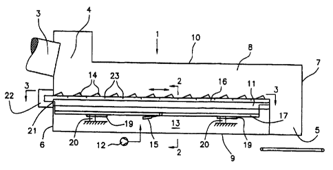
In Figs. 1, 2 and 3 is seen a cooler 1 which is placed in
direct extension of a rotary kiln 3 for manufacturing cement
clinker. The cooler comprises an inlet 4, an outlet 5, end
walls 6, 7, side walls 8, a bottom 9 and a ceiling 10. The
cooler shown also comprises a stationary grate bottom 11 which is
made up of a number of grate plates lla for supporting the cement
clinker, a fan 12 for injecting cooling gas up through the
clinker via a compartment 13 and the grate bottom 11, as well as
a row of scraper elements 14 which can be moved back and forth in
the longitudinal direction of the cooler by a driving means 15,
so that the clinker is conveyed from the inlet end of the cooler
to its outlet end. The cooler may be configured with several
parallel-positioned rows of scraper elements 14. If so, it is
preferred that each row is driven by separate driving means.
The shown cooler further comprises continuously and
automatically operating flow regulators llb which are fitted in
the gas supply duct 11c of each grate plate 11a
CA 02285422 1999-10-O1
WO 98/48231 PCT/EP98102012
for regulating the cooling gas flow up through the grate
plate in question.
In the shown embodiment the scraper elements are
mounted on two vertically positioned drive plates 16 which
5 extend down through slots 24 provided in the grate bottom
- 11, and being supported by a frame structure which is made
up of two longitudinal girders 17 and a number of cross
girders 18. The frame structure is movably supported by
means of rails 19 fixed to the lower side of the
10 longitudinal girders 17 and linear ball bearings 20 which
are fixed to the frame of the machine. It is preferred that
the frame structure is supported by exactly two bearings
for each longitudinal girder because the system thereby
does not become statically undetermined. This will prevent
build-up of internal stresses resulting, for example, from
deformations which would subject the bearings to
unnecessary stress loading.
The drive plates 16 are conf figured with a length which
corresponds to the length of the grate bottom i1 itself
plus the stroke length of the drive plates. In Figs: 1 and
3 the drive plates are shown in their fully retracted
position where each of the plates protrudes through an
opening 21 provided in the inlet end wall 6 of the cooler.
The opening is designed so that it corresponds exactly to
the cross-sectional profile of the drive plate and the
plate element placed thereon. In order to capture dust
which is conducted through the openings 21, a pressurized
box 22 through which the collected dust is returned to the
cooler is fitted at the outer side of the cooler. The box
22 is pressurized by means of air from the compartment 13
or from an external air supply source, such as a fan or a
compressor. The openings 21 may be individually sealed by
means of a sliding seal which is configured complementary
to the plate element placed on the drive plate, and riding
thereon. '
CA 02285422 1999-10-O1
WO 98148231 PCT/EP98102012
11
In connection with the maintenance work, the drive
plates may be pulled out through the end wall 6 or pulled
vertically up through the grate bottom.
As shown in Fig. 1 the drive plates are formed with
slits 23 for absorbing a potential thermal expansion in the
uppermost part of the drive plate to prevent arching of the
drive plate.
In Fig. 4 is shown an example of how the grate surface
11 can be advantageously shielded against fall-through of
material while, at the same time, the drive plate 16 is
protected against wear exposure from the material in the
cooler. In the shown example the sealing arrangement
comprises two angular wall elements 25 being fixed on
either side of the drive plate to the grate bottom 11 and
a plate element 26 which is configured as an inverted U and
which is mounted on the upper side of the drive plate where
it is retained i.a. by means of the scraper elements 14. In
the longitudinal direction of the cooler the wall elements
have the same length as the grate surface 11, whereas
20 the plate element 26 has the same length as the drive
plate. As shown in dotted lines in Fig. 4, the sealing
arrangement may further comprise two wear caps 27 which are
inserted over separate wall elements 25. The position of
the grate plates lla relative to the sealing arrangement is
25 also shown in dotted lines.
Figs. 5a, 5b and 5c show an example of how the scraper
elements 14 can be firmly fixed on a drive plate 16. In the
shown example, fixation is done by means of a block 30 as
shown in Fig. 5a which is formed with a recessed section 31
for accommodating the scraper element, and with two
through-going holes 32. As shown in Fig. 5b, the drive
_ plate 16 is formed with ears 34 which protrude upwards
through cut-out sections in the plate element 26, each
being formed with a through-going hole 35. The position of
the scraper element 14 is shown in dotted lines 36. At
stage of mounting, the scraper element 14 is mounted as
shown in Fig. 5c on the plate element 26 between two ears
CA 02285422 1999-10-O1
WO 98/48231 PCT/EP98/02012
12
34, whereafter the block is placed an top so that the ears
34, as indicated at the left side of the block, protrude up
through the cavities 33 provided in the block, the scraper
element extends through the cut-out section 31, and the
holes 32 in the block are on line with the holes 35 in the
- ears 34. A wedge 37 is then knocked through the holes 32,
35 on both sides of the scraper element 14. The wedges '37
are locked by means of locking pins 38, each of which
extends through the ear 34 and into the wedge 37. The
scraper element 14 is retained by means of a pawl 39 which
is mounted in the scraper element 14, extending up through
a hole 4o provided in the block 30.
As it appears from Figs. 5b and 5c, the scraper
elements are made up of bars with a right angled triangular
profile in section, the forward-facing pushing surface 36a
of which being steeper than its backward-facing sliding
surface 36b, and the downward-facing surface of which being
substantially horizontal. The forward-facing surface
extends at an angle a of between 60 and 90° relative to the
horizontal, whereas the backward-facing surface extends at
an angle /3 of between 20 and 40° relative to the
horizontal. The lowermost part of the backward-facing
sliding surface may be configured so that it is steeper
than the rest of the sliding surface in order to reduce the
sharpness of the backward-facing side edge, thereby
enhancing the wear-resistant characteristics.
Alternatively at least some of the scraper elements may
have their steeper face facing rearwardly, as shown in Fig.
5d; or be of isosceles triangle sectional shape, as shown
in Fig. 5e.
In Fig. 6 is seen a cooler which, in addition to the
movable scraper elements 14, also contains stationary
scraper elements 14a which are fixed to longitudinal
girders 42 fitted at the sides of the supporting surface
11. In the shown embodiment every second scraper element is
stationary. Some of the scraper elements may be omitted at
CA 02285422 1999-10-O1
WO 98/48231 PCT/EP98/02012
23
the inlet end as shown by the dashed line outline of the
elements 14 and 14a in Figs. 3 and 6.
In Fig. 7 is seen an example of how a drive plate 16
can instead be led through a slot 44 provided in the side
wall 8 of the cooler. In the shown embodiment, the scraper
element 14 is mounted on the drive plate 16 via a spacer 45
which provides the necessary space for mounting sealing
means 46. Also fitted above the drive plate 16 are sealing
means 47 for minimizing the leakage of dust and cooling gas
from the cooler.