Note: Descriptions are shown in the official language in which they were submitted.
CA 02285541 1999-10-O1
WO 98/43809 PCT/US98/06706
CARBON-CARBON PARTS HAVING FILAMENTIZED COMPOSITE
FIBER SUBSTRATES AND METHODS OF PRODUCING THE SAME
Background of the Invention
This invention relates generally to carbon-carbon substrates and methods for
producing parts using the substrates, and in particular, to a filamentized
composite
fiber substrate and method for producing a carbon-carbon part using the
substrate.
A brake disc for an aircraft or an automobile requires a material having high
heat resistance and long wear. For some applications. asbestos is used due to
its heat
resistance properties. In addition to asbestos, carbon may also be used,
although
conventional carbon-carbon brake products are expensive and historically
restricted to
aerospace or automotive racing applications.
Generally. a substrate of carbon fiber or carbon precursor may be used to
produce a conventional carbon-carbon part with sufficiently high heat
resistance values
for use in, for example, an aircraft braking system. These conventional parts
require a
complicated time consuming process to produce a part with sufficient carbon to
provide the necessa~ high temperature characteristics. These conventional
carbon-
carbon parts are expensive due to the complicated manufacturing process. There
are a
number of different types of substrates used to make conventional carbon-
carbon parts
CA 02285541 1999-10-O1
WO 98/43809 PCT/US98/06706
2
including discontinuous carbon fiber molding compound, non-woven air lay
carbon
fiber substrates, woven carbon fiber substrates, or braided carbon fiber
substrates.
To produce a conventional carbon-carbon part from a carbon fiber substrate
that may be used, for example, for an aircraft brake disc, a plurality of
carbon fiber
substrates are available. These substrates may be stacked on top of each other
to a
desired thickness and then the stacked substrates may be needle-punched
together, as is
known in the art, to join or consolidate the substrates to each other by
intermingling
carbon fibers between the layers of substrates. This consolidation of the
substrates
creates a preform. The preform may then be batch carbonized, in which the
preform is
placed in an oven at 800 to 1100 degrees Celsius, to char the fiber of the
substrate and
increase the carbon content of the preform. Next, due to shrinking caused by
the
carbonization, the carbonized preform may be die cut to obtain the desired
preform
shape. These preforms may then have additional carbon atoms deposited on the
carbon
fibers of the preforms by using a chemical vapor deposition (CVD) process. In
the
CVD process, the preform is placed in an evacuated chamber and a carbon
bearing gas,
such as methane, is introduced into the chamber which when subjected to
temperature
releases carbon atoms that settle/infiltrate into the preform. The CVD process
may
increase the carbon content and density of the preform. The preform may then
be heat
treated to reorient the carbon atoms to a more energetically favorable
configuration,
machined if necessary, and treated with an anti-oxidant to form the finished
carbon-
carbon part.
CA 02285541 1999-10-O1
WO 98/43809 PCT/US98/06706
The conventional preform process, as described above, and the conventional
carbon-carbon parts have several problems. First, the batch carbonization
process is
slow and time consuming, taking hours or days which increases the cost of the
part.
Second, the batch carbonized preforms made from conventional substrates have a
limited amount of carbon fiber surface area available so that fewer carbon
atoms
generated during the CVD process are able to settle / infiltrate into the
preform. The
lower level of carbon atom pick-up during the CVD process may require that the
preforms undergo additional CVD processing and surface grinding steps to
achieve the
desired density. Third, it is difficult due to the nature of the process to
add chemical or
material additives to the preforms for the enhancement of performance
characteristics
because the additives may only be added to the preform after the consolidation
step.
Fourth, any material removed from the preform during the shaping and die
cutting
processes cannot be re-used because there is no method for recycling this
scrap
material back into the preform manufacturing process. Thus, due to the above
four
problems carbon-carbon parts produced using the conventional preform process
are
typically too expensive to use for most commercial applications.
Another conventional substrate uses carbon fibers that are impregnated with a
suitable binder and then the impregnated substrate may be compressed under
heat and
pressure to form the near net shape preform. The preform is then batch
carbonized to
CA 02285541 1999-10-O1
WO 98/43809 PCT/US98/06706
4
char the binder via condensation of the binder into carbon. The binder may be
liquid
furfilryl alcohol polymer catalyzed with malefic anhydride. Once again, this
substrate
requires a batch carbonization process step in order to char the binder. Still
another
substrate for a carbon-carbon part uses carbon fibers, that may be oxidized
polyacrylonitrile (PAN) fibers that may then be carbonized to form the carbon
preform
that may be subjected to the chemical vapor deposition {CVD) process. This
substrate
also requires a carbonization step.
None of these conventional materials for producing carbon-carbon parts
permits the elimination of the batch carbonization step, which increases the
cost of the
final part. In addition, none of the conventional materials provide a
sufficient surface
area to permit an efficient rate of densification during the CVD process. The
conventional materials also do not provide a method for recycling scrap pieces
of the
substrate for reintroduction into the preform process. As such, conventional
carbon-
carbon parts are too expensive to be used in most conventional commercial
applications.
Thus, there is a need for a composite material substrate and a method for
producing carbon-carbon parts using a substrate which avoids these and other
problems
of the known substrates, processes and carbon-carbon parts, and it is to this
end that the
present invention is directed.
CA 02285541 1999-10-O1
WO 98/43809 PCT/US98/06706
Summary of the Invention
The invention provides a composite material substrate having primarily
filamentized carbon fibers held together by a binder that affords improved
processability over a conventional carbon substrate. The cost of the parts
produced
using the filamentized composite substrate are reduced for several reasons,
including
that the filaments, primarily carbon, in the substrate have more surface area
exposed,
so that fewer fibers are required to achieve the same densification levels and
less of the
substrate is needed for each final part. In addition, any scraps of the
substrate
generated during the process may be easily recycled back into the substrate
manufacturing process. Carbonized carbon fibers used in the filamentized
composite
substrate permit the elimination of a batch carbonization step currently used
with
conventional substrates. Due to the substrate having a higher surface area
than
conventional substrates, a higher percentage of carbon atoms are also attached
to the
filaments during the chemical vapor deposition (CVD) process, which reduces
the time
required to produce a part with a desired density. The binder used in the
substrate is
readily removed during the CVD process so a batch carbonization step is not
necessary.
The reduced cost may make these carbon-carbon parts manufactured from
filamentized composite substrates suitable for conventional commercial
applications.
The invention also provides a substrate for a preform that may have a
plurality
of discontinuous fibers, primarily carbon, held together by a binder compound
wherein
CA 02285541 1999-10-O1
WO 98/43809 PCT/US98/06706
6
the binder compound may be readily displaced during the CVD process. Thus, the
binder may hold the carbon filaments in place prior to the CVD process and
then may
evaporate during the CVD process and be replaced by the carbon atoms.
The invention further provides a substrate that may be produced using a paper
process in which the fibers, primarily carbon, and the binder may be combined
together
to form a substrate that may be used to manufacture a carbon-carbon part. The
process
for producing a filamentized composite substrate may permit additional
chemicals or
materials to be easily added to the substrate via the paper manufacturing
process, to
enhance a variety of characteristics of the substrate and the carbon-carbon
part made
from the substrate, such as its hardness, coefficient of friction, or
oxidative resistance.
In another embodiment of the invention, a completed filamentized composite
substrate
may have resin added to the substrate via a prepregging process in order to
increase the
friction/wear results. This same resin may also be used as a vehicle, such as
a high
solids solution, to distribute special additives into the filamentized
composite substrate
to enhance other properties of the substrate and the carbon-carbon part made
from the
substrate. In another embodiment of the invention, typically the preform for a
carbon-
carbon part is of a thickness greater than that of the individual filamentized
composite
substrate sheet, therefore the preform may consist of a plurality of
filamentized
composite sheet substrates. This plurality would constitute a multilayer
construction to
achieve the desired preform thickness. Thus, the filamentized composite
substrate
CA 02285541 1999-10-O1
WO 98/43809 PCT/US98/06706
7
provides an opportunity to easily tailor the through thickness properties of
the preform
by altering the properties of individual filamentized composite substrates
that are used
to manufacture the preform. As an example, the resin content of the inner
layer
substrates of a preform may be higher than those of the outer layers to
increase the
density of the preform at its interior, which may result in substantially
reduced
chemical vapor deposition (CVD) processing time.
Thus, in accordance with the invention, a carbon-carbon part having a
filamentized composite substrate is provided having a substrate of a plurality
of
discontinuous filaments, primarily carbon, and a binder that binds said
filaments
together to form a substrate, and a plurality of substrates consolidated to
form a
preform, and a plurality of carbon atoms deposited onto the filaments at a
predetermined temperature and pressure such that said binder is removed
completely
from said filaments and replaced by said carbon atoms to form a dense carbon-
carbon
part.
A method for producing a carbon-carbon part is also provided, comprising
producing a substrate, the substrate comprising a plurality of discontinuous
filaments,
primarily carbon, and a binder that binds said filaments together to form a
substrate,
producing a preform by consolidating said substrates, and depositing carbon
atoms, by
chemical vapor deposition (CVD) at a predetermined temperature and pressure
onto
CA 02285541 1999-10-O1
WO 98/43809 PCT/US98106706
8
the filaments such that said carbon atoms replace said binder within said
preform and
said carbon atoms densify said preform to form a carbon-carbon part.
Brief Description of the Drawings
Figure 1 is a diagram illustrating a conventional process for producing carbon-
carbon parts;
Figure 2 is a diagram of a conventional process for forming a preform;
Figure 3 is a flowchart illustrating an overall process for producing carbon-
carbon parts with filamentized composite substrates in accordance with the
invention;
Figure 4 is a diagram illustrating a process for generating the composite
paper
in accordance with the invention that is part of the overall process shown in
Figure 3;
Figure 5 is a diagram illustrating a first embodiment of a process for
producing
filamentized composite preforms in accordance with the invention that is part
of the
overall process of Figure 3;
Figure 6 is a diagram illustrating a second embodiment of a process for
producing filamentized composite preforms in accordance with the invention
that is
part of the overall process of Figure 3;
Figure 7 is a diagram illustrating a third embodiment of a process for
producing
preforms in accordance with the invention;
Figure 8 is a diagram illustrating a fourth embodiment of a process for
producing preforms in accordance with the invention;
CA 02285541 1999-10-O1
WO 98/43809 PCT/US98/06706
9
Figure 9 is a diagram illustrating a fifth embodiment of a process for
producing
preforms in accordance with the invention;
Figure 10 is a micrograph of a cross-section of a pressed carbon-carbon
preform made with the filamentized composite substrate in accordance with the
invention prior to the chemical vapor deposition (CVD) process step;
Figure 11 is a micrograph of a cross-section of a pressed carbon-carbon part
in
accordance with the invention after the CVD process step;
Figure 12 is a micrograph of a surface of a pressed carbon-carbon part made
with the filamentized composite substrate in accordance with the invention
after the
CVD process step;
Figure 13 is a close-up micrograph of a carbon filament coated with carbon
atoms from the CVD process;
Figure 14 is a micrograph of a cross-section of a needle-punched carbon-carbon
part showing reorientation via needle-punching of the carbon filaments from
the X-Y
direction to the Z direction, after the CVD process step;
Figure 15 is a micrograph of a surface of a needle-punched carbon-carbon part
in accordance with the invention, after the CVD process step.
CA 02285541 1999-10-O1
WO 98/43809 PCT/US98/06706
Detailed Description of a Preferred Embodiment
The invention is particularly applicable to using a filamentized composite
substrate to produce carbon-carbon parts for friction applications. It is in
this context
that the invention will be described. It will be appreciated, however, that
the system
and method in accordance with the invention has greater utility. To better
understand
the invention, a brief description of the conventional carbon fiber substrate
and the
conventional process for producing carbon-carbon parts will be provided.
Figure 1 is a diagram illustrating a conventional process 20 for producing a
carbon-carbon part, such as a brake disc for an aircraft braking system. In a
first step
22, a plurality of commercially available carbon fiber substrates may be
obtained. In
step 24, the substrates may be stacked on top of each other to a desired
thickness. The
stacked substrates may then be needle-punched, as is known in the art, to
reorient some
of the fibers from a particular substrate layer through to another substrate
layer so that
some of the fibers within and between the substrates become intermingled
through the
Z plane direction. The fibers in the stacked substrates are intermingled
together and
the interlaminar strength of the resulting preform is increased. Due to
shrinkage that
may occur during the batch carbonization step, the preform must be designed to
be
oversized. Next in step 26, the preforms may be batch carbonized in an oven,
for a
period of several hours up to a few days, at approximately 800 to 1100 degrees
Celsius
in a non-oxidizing atmosphere. During the carbonization process a condensation
of the
CA 02285541 1999-10-O1
WO 98/43809 PCT/US98/06706
11
preform material occurs causing the preform to shrink somewhat and the
resulting
carbonized preform may be die cut in step 28 to the desired size.
The carbonized preform may now be densified, in step 30, in which carbon
atoms may be added to fill in the free volume between carbon fibers resulting
in
increased part density. Generally, to add the carbon atoms, a chemical vapor
deposition (CVD) process is used in which the carbonized parts are placed in a
heated
evacuated chamber and a carbon containing gas, such as methane, is introduced
into
the chamber so that the carbon atoms from the methane may impregnate the
preform.
However, the conventional preform composed of bundled fiber filaments may have
a
limited amount of carbon fiber surface area for the carbon atoms to deposit
on, which
may reduce the rate of densification. Conventional preforms containing bundled
fiber
filaments and having non-uniform pore size openings may be prone to surface
clogging
requiring the surface to be ground followed by additional chemical vapor
deposition
(CVD) processing.
Once desired densification has been reached, in step 32, the densified part
may
be heat treated to reorient the carbon atom matrix to a more energetically
favorable
configuration. Next, in step 34, the carbon-carbon part is machined to the
desired final
dimensions. Finally, in step 36, an anti-oxidant layer may be added to exposed
CA 02285541 1999-10-O1
WO 98/43809 PCT/US98J06706
12
surfaces of the part. The anti-oxidant layer is designed to prevent surface
oxidation of
the carbon-carbon part.
Figure 2 is a diagram of a conventional process for forming a preform. A
plurality of mats 60 of bundled filament substrate on woven or discontinuous
chopped
tow may be needle-punched by a needle loom 62 to intermingle the filaments
from
each substrate together. A part cutter 64 may cut circular parts out of the
plurality of
mats. The results of the part cutting is a plurality of circular parts 66 and
a large
amount of trim 68 that cannot be easily recycled. A finished preform 70 is
shown.
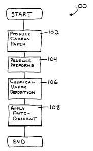
Figure 3 is a flowchart of an overall method 100 for producing carbon-carbon
parts from a filamentized composite substrate in accordance with the
invention. In a
first step 102, a composite paper substrate is produced in accordance with the
invention. The composite paper substrate will be referred to hereinafter as a
filamentized composite (FC) substrate. The FC substrate may have a plurality
of
discontinuous fibers, primarily carbon, such as polyacrylonitrile (PAN) based
carbon
fibers and/or Pitch based carbon fibers with random orientations bound by an
alcohol
based binder. The alcohol based binder, as described below, may have a
sufficiently
low flash point so that the alcohol based binder may be easily displaced from
the
carbon filaments during the CVD process. In addition, resins and material
additives
may be added to the FC substrate that enhance certain characteristics of the
finished
CA 02285541 1999-10-O1
WO 98143809 PCT/US98/06706
13
carbon-carbon part. The details of the production of the FC substrate and the
components of the FC substrate will be described below with reference to
Figure 5.
The production of the preforms may include stacking a plurality of layers of
the FC
substrate onto each other and, in a first embodiment, needle-punching the
layers
together as described below with reference to Figure 6, or in a second
embodiment,
pressing the layers together as described below with reference to Figure 7, in
a third
embodiment or, pressing and then needling the preforms as shown in Figure 8,
or in a
fourth and fifth embodiment, needling and pressing the preforms as shown in
Figure 9
and 10. Additional consolidation methods may include consolidation by
combination
of needle-punching and pressing, in either order. The cutting of preforms to
shape may
be performed either prior to consolidation, at the FC substrate stage, or
subsequent to
consolidation, at the preform stage.
With any of the aforementioned methods for producing the preforms, any scrap
material generated in cutting the shapes of the preform may be recycled. The
scraps
may be reintroduced back into the composite paper production process. The
alcohol
based binder in the FC substrate is soluble in water so that scrap material
may be
reused to make additional FC substrates. By contrast, in the conventional
process
described above, any scrap material generated during the cutting process must
be
discarded because there is no easy way of recycling the scrap material back
into the
original form required by the process. The preforms produced may have a
plurality of
CA 02285541 1999-10-O1
WO 98/43809 PCT/IJS98106706
14
substrate layers depending on the desired application thickness. The PAN based
and/or
Pitch based carbon fibers utilized are previously carbonized in an economical
continuous process and preforms produced from same fibers do not require any
further
carbonization. In addition, the binder in the FC substrate may be evaporated
cleanly
from the carbonized filaments during the CVD process, as described below, so
that the
carbonization of the binder is also not required. Therefore, the preforms
produced
using the FC substrate in accordance with the invention do not require a
carbonization
step, which reduces considerably the time necessary to produce the carbon-
carbon part
and reduces its cost.
Once the preforms have been produced from the FC substrate, the preforms
may be subjected to a CVD process 106 in which the substrates are placed
within an
evacuated heated chamber. Then, a carbon containing gas, such as methane, is
introduced into the chamber, and the carbon atoms from the gas may
settle/infiltrate
onto the filaments, filling in the free volume between the filaments to
increase the part
density. An example of a FC substrate showing the increased preform surface
area
prior to the chemical vapor deposition {CVD) process will be described below
with
reference to Figures 10-15. The polyacrilonitrile (PAN) based and/or Pitch
based
filaments and other filament types in the FC substrate may have a large amount
of
surface area so that a large amount of carbon atoms may better impregnate the
preform
reaching the desired densification at a faster densification rate than
conventional
carbon fiber preforms such as those composed of bundled carbon filament
substrates.
CA 02285541 1999-10-O1
WO 98/43809 PCT/US98/06706
In addition, the larger amount of surface area due to a higher and more
uniform surface
porosity makes the preform composed of FC substrates less prone to surface
clogging
during the CVD process. Therefore, the grinding steps) and additional CVD
steps)
required for a conventional part that has a propensity for surface pore
clogging rnay not
be required. Thus, the preforms made of the FC substrate construction, in
accordance
with the invention, may have a higher densification rate than a conventional
part and
may not require grinding steps) or an additional CVD step(s), which further
reduces
the cost of the FC substrate based carbon-carbon parts. After the CVD process
and
heat treatment process, an anti-oxidant layer may be applied to the exposed
surface of
the part in step 108 to prevent surface oxidation. After the anti-oxidant
layer has been
applied, a completed carbon-carbon part has been produced. Now, a method of
producing the composite paper will be described.
Figure 5 is a diagram illustrating a process for producing the composite paper
that may be used for the carbon-carbon parts in accordance with the invention.
In a
first step 120, a plurality of carbonized PAN based and/or carbonized Pitch
based
fibers and other type fibers and an alcohol based binder may be combined
together in
an aqueous solution. The binder may preferably by polyvinyl alcohol (PVA) as
described below. The fibers used for the paper may be discontinuous fibers
that may
be oriented in random directions which increases the strength of the paper.
The fibers
used to produce the paper may preferably be carbonized polyacrylonitrile (PAN)
based
CA 02285541 1999-10-O1
WO 98/43809 PCT/US98/06706
16
or carbonized Pitch based carbon fibers or a refractory type fiber or metallic
type fiber
or combination thereof, where preferably 50 percent of the fibers are 0.50
inches long
and 50 percent of the fibers are 1.00 inch long. The invention is not limited
to the
particular proportions of the fibers and the composite paper may be composed
entirely
of fibers as short as 0.25 inches and as long as 1.5 inches long fibers, or
some
percentage of both. The fiber filaments may preferably be about 7-10 microns
in
diameter but the range of 3-16 microns may be used. Once the alcohol based
binder
and the fibers are combined together, as with a conventional paper process, in
step 122,
the combination of the filamentized fibers and the alcohol based binder may be
placed
on a conveyor to form a web of composite material, such as the composite
paper. Then
in step 124, the water is removed from the composite paper to produce the dry
composite paper. The dry composite paper I26 may be composed of 2-12 percent
by
weight of polyvinyl alcohol (PVA) and 88-98 percent by weight of the fiber
filaments.
The preferred composite paper may have 5 percent PVA and 95 percent carbonized
PAN based carbon filaments. A plurality of discontinuous carbonized PAN
filaments
128 may be randomly oriented within the composite paper such that there may be
an
entangled mass of filaments within the composite paper held together by the
PVA
matrix to enhance handleability for further processing.
The utilization of carbonized PAN based and/or carbonized Pitch based carbon
fibers in the composite paper eliminates the batch carbonization process that
is
..__..._. _ .._.___V_~__.~_ _.. ._.. _..___... _..__ ~......_.._.._ _ _._ ..
CA 02285541 1999-10-O1
WO 98/43809 PCT/US98/06706
17
conventionally required to produce carbon-carbon parts. The PVA aids in
binding the
carbon filaments together during the stacking, needle-punching and pressing of
the FC
substrates so that no additional reinforcement is required. The PVA may also
have a
low flash point so that when the preform composed of FC substrate layers is
subjected
to the CVD process, as described above, the PVA may be completely driven off
of the
filaments due to the temperature of the CVD process and the carbon atoms of
the CVD
process may easily fill in the areas around the filaments vacated by the PVA.
Thus, the
PVA may hold the filaments together in the composite paper during the initial
stacking,
needle-punching, and pressing of the preforms, but may then be removed
entirely from
the filaments during the CVD process. The surface of the preforms made from FC
substrates, prior to and after CVD processing, will be described below with
reference
to Figures 10-15.
The combination of the filamentized fibers and the PVA also provide more
preform surface area for the carbon atoms to deposit on during the CVD process
because the PVA is completely removed from the filaments at the beginning of
the
CVD process. Therefore a maximum amount of preform surface area is exposed and
a
maximum number of carbon atoms deposit on the surfaces of the preform. This
results
in more efficient use of the fibers due to the increased surface area of the
preform and
subsequent increase in the amount of carbon atoms that may deposit (i.e.
densification)
CA 02285541 1999-10-O1
WO 98/43809 PCT/US98/06706
18
on the filaments. Thus, the time required to densify the preform is reduced
and less
fiber is required, which reduces the cost of the carbon-carbon part.
The production of the FC substrate may also be easily modified to add
additional resins and/or materials that may enhance a certain characteristic
of the
carbon-carbon part. The additional chemicals or materials may be added to the
aqueous solution to impart those same chemicals or materials to the composite
paper or
those same chemicals or materials may be imparted to the FC substrate via a
prepregging process. For example, a ceramic may be added to the FC substrate
which
may adjust the hardness of the substrate and correspondingly the hardness of
the
carbon-carbon part. As another example, boron micro-particles may be added to
the
FC substrate so that the carbon-carbon part has a lower coefficient of
friction that may
be desirable for wear type applications, such as brake discs. As another
example,
carbon micro-particles may be added to the FC substrate which increases the
carbon
content of the preform prior to CVD resulting in reduced time and cost of CVD
processing. Furthermore, in the case where the preform constitutes a plurality
of FC
substrates as in a multilayer construction, modifications to the preform
properties can
be made by altering the properties of the individual FC substrates that are
consolidated
into the preform. Now, a first embodiment of a method for producing a preform
that
may be part of the carbon-carbon part production method, in accordance with
the
invention, will be described.
CA 02285541 1999-10-O1
WO 98/43809 PCT/US98/06706
19
Figure 6 is a diagram illustrating a process 140 for producing a preform from
a
FC substrate via a needle-punching process that may be part of the production
of the
carbon-carbon part. First a plurality of FC substrate sheets 142 may be
stacked
together and fed into a needle loom 144, as is well known, and the stack of FC
substrates may be consolidated by needle-punching some of the filaments from
an X-Y
direction to a Z direction. The height of the FC substrate stack depends on
the desired
preform thickness for a particular application. Preform thickness for typical
applications may range from 0.125 inches to 2 inches. After needle-punching,
parts
may be cut out of the consolidated layers of FC substrates by a part cutter
146 to make
a sheet 148 of cut preforms 150 having the desired shape. The cut parts may
then be
separated to form a plurality of finished preforms 152 that may be densified
using the
chemical vapor deposition (CVD) process. A portion of 153 the FC substrate
sheet not
used to produce parts may be recycled in accordance with the invention. Now, a
second embodiment of a method for producing a preform that may be part of the
carbon-carbon part will be described.
Figure 7 is a diagram illustrating a second method 160 for producing a
w
composite preform from FC substrate sheets. First, a plurality of sheets of FC
substrates 162 may be fed into a part cutter 164 which cuts the substrates
into the
desired shape. For the desired thickness of the preform, the appropriate stack
height of
CA 02285541 1999-10-O1
WO 98/43809 PCT/US98/06706
cut FC substrates are fed into a presser 166 that may press the layers of FC
substrates
within the stack together to form a consolidated preform 168 that may then be
densified by the CVD process. Either of the methods shown in Figures 6 and 7
may be
used individually or in a combined process to form the preforms that are later
densified, but it is preferred that the FC substrate sheets be needle-punched
prior to
pressing because the interlaminar strength of the needle-punched preforms is
increased.
The pressing cycle for any of the embodiments for a PAN-based substrate may
have a pressing time that may be between 2 to 20 minutes, and may preferably
be
about 7 minutes. The temperature of the pressing may be between 300 to S00
degrees
Fahrenheit, and may preferably be about 400 degrees Fahrenheit. The pressure
range
of the pressing may be between 100 to 2,500 pounds per square inch (psi), and
may
preferably be about 500 psi. The pressing step may permit the binder to be
mingled
between the layers of the sandwich which may bind the layers together. The
pressing
may also decrease the free volume of the sandwich and increase the fiber
volume of the
preform. The pressing characteristics for a substrate with different filaments
may vary
depending on the configuration and/or composition of the filamentized preform
matrix.
Figure 8 is a diagram of a third embodiment for forming a preform in
accordance with the invention. As shown, a filamentized fiber substrate 180,
that may
have a plurality of layers, may be pressed by a press 182 and then needled by
a needle
CA 02285541 1999-10-O1
WO 98/43809 PCT/US98/06'706
21
loom 184 which intermingle the filamentized fibers in each layer of the
substrate.
Next, a part cutter 186 may cut each circular disc to form a consolidated
preform 188
that may then be subjected to the CVD process step.
Figures 9 and 10 are diagrams depicting a fourth and fifth embodiment of a
method of forming a preform. In both embodiments, a filamentized fiber
substrate
190, that may have a plurality of layers, may be needle punched by a needle
loom 192.
In Figure 9, the needled substrate may be pressed by a press 194 and cut into
discs by a
part cutter 196 to form consolidated parts 198. In the embodiment shown in
Figure 10,
the needled substrate may be cut into discs and then each disc may be pressed
to form
the consolidated preforms 198. Now, a sample of the pressed carbon-carbon
part, as
described above, prior to and after the CVD process will be compared to a
needle-
punched carbon-carbon part, as described above, prior to and after the CVD
process.
Figures 10-15 are micrographs depicting the cross-sections and surfaces of the
pressed and needle-punched carbon-carbon parts produced that both use the FC
substrate. Figure 10 is a micrograph showing a cross-section of a carbonized
polyacrylonitrile (PAN) based carbon fiber preform that has been pressed, as
described
above with reference to Figure 7, prior to the CVD process. As shown, the
carbon
filaments may have some polyvinyl alcohol (PVA) binder bonded to the carbon
filaments that will be driven off during the CVD process. The carbon filaments
may be
CA 02285541 1999-10-O1
WO 98/43809 PCT/US98/06706
22
generally in the X-Y direction. Figure 11 is a micrograph showing a top
surface of the
pressed carbon-carbon part after the CVD process wherein the volume around the
carbon filaments has been filled in by the CVD process. Figures 12 and 13 are
micrographs showing a close-up view of the top surface of the pressed carbon-
carbon
part. As shown, the surface may have an "onion skin" like carbon morphology
formed
around the carbon filaments. Figure 14 is a micrograph of a cross-section of a
needle-
punched carbon-carbon part after the CVD process. As shown, some of the carbon
filaments normally in the X-Y direction have been reoriented into the Z
direction due
to the needle-punching, which increases the interlaminar strength of the
carbon-carbon
part. Figure 1 S is a micrograph of a top surface of the needle-punched carbon-
carbon
part showing the "onion skin" morphology due to the deposited carbon from the
CVD
process.
A second embodiment of the carbon-carbon part produced using the FC
substrate, in accordance with the invention, will now be described. In this
embodiment, a resin, such as phenolic resin, may be added or prepregged onto
the FC
substrate that is described above. With the addition of the resin, the FC
substrate must
be batch carbonized prior to the CVD process, which has the disadvantages
described
above. However, the resin prepregged FC substrate has several advantages. The
resin
based carbon-carbon part has improved friction / wear results that are very
desirable for
friction applications. In particular, the presence of the phenolic resin in
the carbon-
_ _.~.. __.~ ._~__..~~._._..~..._ _. ..__~ ..... _ _ ..._~~_._._ ..~.~ .___.,.
CA 02285541 1999-10-O1
WO 98/43809 PCT/US98/06706
23
carbon part provides a glassy form of carbon that reduces the coefficient of
friction of
the carbon-carbon part and extends the wear life of the carbon-carbon part in
a friction
application, such as brake discs. The phenolic resin may be used as a vehicle,
such as
in a high solids solution, to introduce other wear additives and friction
reducing
elements into the FC substrate that would otherwise most likely need to be
added
during the CVD process, further complicating the already lengthy CVD process.
The
carbonized phenolic resin may also occupy some of the volume in the FC
substrate that
would otherwise need to be filled in during the CVD process. The carbonized
phenolic
resin may be concentrated to the interior thickness of the preform where
multiple FC
substrates or multilayer construction is used. This reduces the overall time
and
expense of the CVD process. The range of phenolic resins in the embodiment of
the
carbon-carbon part may be from 2 percent to 60 percent by weight, depending on
the
particular desired characteristics of the finished carbon-carbon part. Once
the resin has
been prepregged onto the FC substrate, the FC substrate, as described above,
may be
carbonized, densified through a CVD process and machined into the finished
carbon-
carbon part.
While the foregoing has been with reference to particular embodiments of the
invention, it will be appreciated by those skilled in the art that changes in
these
embodiments may be made without departing from the principles and spirit of
the
invention, the scope of which is defined by the appended claims.