Note: Descriptions are shown in the official language in which they were submitted.
CA 02285743 1999-10-08
DIRECTIONAL ENDOSCOPIC SURGICAL DEVICE
FIELD OF THE INVENTION
The invention relates to the field of surgical instruments and, more
specifically, to remotely operable surgical devices used in conjunction with
endoscopes,
gastroscopes, colonoscopes and similar elongated diagnosis and treatment
instruments used
to guide such remotely operable surgical devices to surgical sites within a
patient's body.
The invention also relates to methods for using such remotely operable
surgical devices
in conjunction with endoscopes, gastroscopes, colonoscopes and the like.
BACKGROUND OF THE IlWENTION
In obtaining a biopsy of a patient's esophageal or other tract organ tissues
via an end-viewing endoscope, the distal end of the scope must be turned to
the side to
aim the instrument in the direction of the tissues to be sampled in order to
correctly direct
a biopsy needle or forceps as such instrument emerges from the distal end
opening of the
instrument lumen of the endoscope. In addition, the conical field of view
provided by the
endoscope's optical element is generally on the order of about 90 , centered
along the axis
of the scope's distal end portion. This procedure is frequently difficult,
however, owing
to the narrowness of the esophagus. Although a side-viewing endoscope can be
used to
obtain an esophageal biopsy, the scope is nearly useless in examining the
stomach, thus
often necessitating use of both an end-viewing endoscope and a side-viewing
endoscope
during the same surgical procedure. Accordingly, a need exists for a device to
facilitate
the obtaining of an esophageal or other narrow tract organ biopsy via an end-
viewing
endoscope.
CA 02285743 1999-10-08
2
Some endoscopes include two separate biopsy channels for the simultaneous
insertion of multiple endoscopic instruments. In addition, U.S. Pat. Nos.
5,025,778 and
4,646,722 to Silverstein et al. disclose the application, to endoscope
insertion members,
of removable sheaths having expandable biopsy channels. Such endoscope sheaths
enable
any existing endoscope to be retrofitted to have multiple biopsy channels.
Such multiple
biopsy channels, however, cannot be used to their full potential, without the
existence of
flexible endoscopic instruments with distal end portions which can be turned
or directed
by an operator at the proximal ends of the instruments. One solution is to
provide each
endoscopic instrument with its own set of orientation control cables. Although
this
solution is certainly feasible, a less expensive solution would be beneficial.
Another proposed solution is disclosed in U.S. Patent No. 5,386,818, which
discloses an endoscopic instrument comprising an endoscope insertion tube
provided with
a biopsy channel and an elongate tubular member inserted into the biopsy
channel; the
tubular member being provided with a distal end portion having a spring bias
tending to
form the distal end portion into an arcuate configuration. The tubular member
is
longitudinally slidable in the biopsy channel, whereby the distal end portion
may be
alternately maintained in a relatively straightened configuration in a distal
end of the
biopsy channel and moved outside of the biopsy channel to assume the arcuate
configuration. An elongate flexible endoscopic instrument is slidably inserted
into the
tubular member so that an operative tip at a distal end of the instrument may
project
outwardly from the distal end portion upon an ejection of at least a part of
the distal end
portion of the tubular member from the biopsy channel. Such apparatus suffers
from a
number of disadvantages, however, due to the limited field of vision at the
distal end of
the scope. Because the spring-biased portion of the tubular member starts to
bend as soon
as it is extended beyond the tip of the endoscope, the end of the tubular
member quickly
directs the instrument to a location potentially outside the operator's field
of view. Upon
further movement of the tubular member distally of the scope's tip, the
tubular member
turns back on itself, directing the instrument to a position proximal to scope
tip and
completely out of view of the operator. Thus, while the instrument disclosed
in U.S.
Patent No. 5,386,818 may be satisfactory for some procedures, a surgical
instrument
which remains in the operator's field of view when directed perpendicular to
the
scope's axis would be particularly advantageous.
CA 02285743 1999-10-08
3
SUMMARY OF THE IlWENTION
An object of the present invention is to provide a surgical device utilizable
with an endoscope, gastroscope, colonoscope or other flexible or rigid
elongated
diagnostic and/or treatment tool which device is more easily guided to a
surgical or
diagnostic site within a patient's tract organ or other remote internal body
portion.
A related object of the present invention is to provide a method for
facilitating the performance of a surgical operation, e.g., the taking of a
biopsy, via an
endoscope or similar instrument.
Another, more particular, object of the present invention is to provide such
a device which is inexpensive to manufacture and easy to use.
A further object of the present invention is to provide a method and/or an
associated instrument assembly or apparatus for use in directing the distal
end of a
surgical instrument distally out of the end of an endoscope and then laterally
toward a
surgical site in controlled, repeatable fashion, and always within the scope
operator's field
of view.
Another specific object of the present invention is to provide such a method
and/or an associated instrument assembly or apparatus which reduces the costs
of
endoscopic procedures.
An improved surgical instrument assembly comprises, in accordance with
the present invention, an endoscope or other body insertion tube provided with
an
instrument channel and a sheathed elongate tubular member inserted into the
instrument
channel. The tubular member is provided with a distal end portion having a
pair of
resilient curved portions tending to direct the tip of the distal end portion
in a direction
angularly offset from the axis of the body insertion tube at its distal end.
The elongate
tubular member is longitudinally slidably positioned within a relatively
stiff, straight
sheath having mechanical properties sufficient to straighten the curved
portions of the
tubular member when the curved portions are positioned within the sheath,
proximal of
the sheath's distal end. An elongate flexible endoscopic instrument is mounted
into the
tubular member so that an operative tip is located at a distal end of the
tubular member.
Alternatively, an endoscopic instrument may be slidably housed in the tubular
member and
may be projectable outwardly from the distal end of the tubular member.
In another embodiment of the invention, the relatively stiff sheath may have
resilient curved portions preformed therein, and the tubular member/endoscopic
instrument
CA 02285743 2004-10-18
4
assembly may be straight in its unstressed or relaxed condition. The curved
portions of the sheath, in this case, would only assume their curved
configurations in the absence of a straightening force applied thereto by the
endoscope's instrument channel walls.
According to the present invention, there is also provided a device
for use in medical procedures involving the use of an elongate body insertion
tube having a longitudinally extending instrument channel there through,
comprising:
an elongate, flexible yet relatively stiff sheath sized so as to be
insertable into the channel, the sheath being provided with a distal end
portion
having a bias tending to form the distal end portion into at least a first,
proximal
bend in the absence of an external straightening force on the distal end
portion,
whereby the distal end portion may be alternately maintained in a relatively
straightened configuration in a distal end of the body insertion tube and
moved
outside of the body insertion tube to selectively assume at least a singly
bent
configuration;
an elongate tubular member inserted into the sheath, the tubular
member being longitudinally slidable in the sheath; and
an elongate surgical instrument having an operative tip, the
instrument being positioned in the tubular member so that the operative tip
extends distally from a distal end portion of the tubular member.
According to the present invention, there is also provided a method
for use in surgical procedures, comprising the following steps in the
following or
any other order:
providing a body insertion tube having a longitudinal instrument channel
therethrough;
inserting a sheathed elongate tubular member into said channel, said sheath
being formed with a distal end portion having a bias tending to form said
distal end
portion into at least a first, proximal bend in the absence of an external
straightening force
on said distal end portion;
placing a distal end portion of the tubular member within the 'sheath;
CA 02285743 2007-03-16
4a
providing an elongate flexible surgical instrument in said tubular member,
said instrument having a distal operative tip;
inserting a distal end segment of said body insertion tube into a patient;
upon insertion of said distal end segment into a patient, pushing said
sheathed tubular member in a distal direction to eject at least a part of said
sheathed
tubular member from said channel, thereby selectively causing said distal end
portion of
the sheath to assume at least a singly bent configuration by action of said
bias; and
moving the tubular member distally with respect to the sheath to eject at
least said operative tip from a distal end of the sheath.
According to the present invention, there is also provided a surgical
assembly comprising:
an elongate body insertion tube having a longitudinally extending instrument
channel therethrough;
an elongate, flexible yet relatively stiff sheath inserted into the channel;
an elongate tubular member inserted into the sheath, the tubular member
being provided with a distal end portion having a bias tending to form the
distal end
portion into at least a first, proximal bend in the absence of an external
straightening force
on the distal end portion, the tubular member being longitudinally slidable.in
the sheath,
whereby the distal end portion may be alternately maintained in a relatively
straightened
configuration in a distal end of the sheath and moved outside of the sheath to
selectively
assume at least a singly bent configuration; and
an elongate surgical instrument having an operative tip, the instrument being
positioned in the tubular member so that the operative tip extends distally
from the distal
end portion of the tubular member.
According to the present invention, there is also provided a device
for use in medical procedures involving the use of an elongate body insertion
tube having a longitudinally extending instrument channel therethrough,
comprising:
an elongate, flexible yet relatively stiff sheath sized so as to be
insertable into the channel;
CA 02285743 2007-03-16
4b
an elongate tubular member inserted into the sheath, the tubular
member being provided with a distal end portion having a bias tending to form
the distal end portion into at least a first, proximal bend in the absence of
an
external straightdning force on the distal end portion, the tubular member
being
longitudinally slidable in the sheath, whereby the distal end portion may be
alternately maintained in a relatively straightened configuration in a distal
end of
the sheath and moved outside of the sheath to selective assume at least a
singly bent configuration, the tubular member comprising a distal end portion
having a bias also tending to form the distal end portion into at least a
second,
distal bend in the absence of an external straightening force on the distal
end
portion, the distal end portion being capable of being alternately maintained
in a
relatively straightened configuration in a distal end of the sheath and moved
outside of the sheath to selectively assume at least a singly bent or a doubly
bent configuration; and
an elongate surgical instrument having an operative tip, the
instrument being positioned in the tubular member so that the operative tip
extends distally from the distal end portion of the tubular member.
According to the present invention, there is also provided a method
for use in surgical procedures, comprising the following steps in the
following or
any other order:
providing a body insertion tube having a longitudinal instrument channel
therethrough;
inserting a sheathed elongate tubular member into said channel, said tubular
member being formed with a distal end portion having a bias tending to form
said distal end portion into at least a first, proximal bend in the absence of
an external
straightening force on said distal end portion;
placing the distal end portion entirely within the sheath;
providing an elongate flexible surgical instrument in said tubular member,
said instrument having a distal operative tip;
CA 02285743 2007-03-16
4c
inserting a distal end segment of said body insertion tube into a patient;
upon insertion of said distal end segment into a patient, pushing said
sheathed tubular member in a distal direction to eject at least a part of said
sheathed distal
end portion from said channel; and
upon ejection of said part of said distal end portion from said channel,
moving the sheath proximally with respect to the tubular member to unsheath
said distal
end portion, thereby selectively causing said distal end portion to assume at
least a singly
bent configuration by action of said bias.
Preferably, the method of performing endoscopic, gastroscopic,
colonoscopic or similar procedures comprises, in accordance with the present
invention, the steps of (a) providing an endoscope or the like having an
instrument channel, (b) providing a sheathed elongate tubular member
insertable into the biopsy channel, the tubular member being formed with a
distal end portion having a pair or resiliently curved portions tending to
direct the
tip of the distal end portion in a direction angularly offset from the axis of
the
body insertion tube at its distal end, (c) providing an elongate flexible
endoscopic instrument mounted in or slidably insertable into the tubular
member, the instrument having an operative tip at a distal end, (d) inserting
a
distal end segment of the insertion tube into a patient, (e) pushing the
sheathed
tubular member in a distal direction to eject at least a part of the sheathed
distal
end portion thereof from the instrument channel, in the patient, and (f) while
maintaining the distal end of the sheathed tubular member within the
operator's
field of view, advancing the tubular member with respect to the sheath,
thereby
selectively causing one or both curved portions of the tubular member to be
ejected distally from the sheath and thereby causing the end of the tubular
member to deflect a predetermined angle with respect to the longitudinal axis
of
the scope under the action of the action of the tubular member's resilient
bias
force. Subsequent steps include (g) operating on internal tissues of the
patient
with the operative tip.
According to preferable features of the present invention, the
method further comprises the step of disposing a portion of the sheathed
tubular
CA 02285743 2007-03-16
4d
member within the instrument channel prior to the introduction of the
endoscope
or similar body insertion tube into the patient. This step is particularly
useful
where the instrument channel is a permanent part of the endoscope or body
insertion tube. In addition, the endoscopic instrument may be inserted into
the
tubular member prior to the disposition of the sheathed tubular member inside
the instrument channel of the body insertion tube.
Alternatively, the endoscopic instrument or the like may be inserted
into the sheathed tubular member inside the instrument channel of the scope or
other device.
Preferably, where the endoscope or body insertion tube is flexible
and provided with actuator means for controlling a distal end orientation
thereof,
the method further
CA 02285743 1999-10-08
comprises the step of operating the actuator means to turn the distal end of
the body
insertion tube upon at least partial insertion of the body insertion tube into
the patient,
positioning the distal end portion of the tubular member within the turned
portion of the
body insertion tube, and advancing the tubular member with respect to the
sheath, thereby
5 causing the tubular member to become oriented in a predetermined direction
as a result
of the tendency of the curved portions thereof to follow the turn of the
distal end of the
body insertion tube.
The extent to which the tubular member projects from the relatively stiff
sheath will determine the angle between the distal end portion of the tubular
member and
the axis of the endoscope or body insertion tube at the distal end thereof,
i.e., whether
one or both curved portions are advanced beyond the distal tip of the sheath.
Thus, to
control the angular orientation of the instrument with respect to the axis of
the endoscope
once the distal end of the sheath is projecting distally of the endoscope's
distal end; the
operator controls the relative-axial positions of the tubular member and the
sheath,
independent of how far beyond the distal end of the instrument channel the
sheath is
advanced.
Other embodiments of the invention may include an elongate tubular
member having more than two curved portions, i.e., three or more such curved
portions.
In this manner of construction, the oblique angle of approach is more finely
controllable,
according to the number of curved portions ejected distally from the sheath.
A device and method in accordance with the present invention greatly
facilitates the performance of endoscopic, gastroscopic, colonoscopic and
other similar
tract organ or remote surgery by facilitating the guiding of a surgical
instrument to a
surgical site.
BRIEF DESCRIPTION OF THE DRAWINGS
These and other objects of the present invention will be apparent from the
drawings and detailed descriptions herein, in which:
FIGURE 1 is a schematic side perspective view of an embodiment of the
invention;
FIG. 2 is a cross sectional view of the device of FIG. I taken along line
2-2;
CA 02285743 1999-10-08
6
FIG. 3 is a partial schematic side perspective view of the embodiment of
FIG. 1;
FIGS. 4-5 are partial sectional views of the embodiment of FIG. 1 at
different steps of operation of the apparatus according to the invention;
FIGS. 6-7 are partial sectional views of the embodiment of FIG. 1 at
different steps of a surgical procedure performed according to the invention;
FIG. 8 is a partial schematic sectional view of an embodiment of the
invention at a step of a surgical procedure according to the invention;
FIG. 9 is a partial schematic sectional view of a prior art surgical device;
and
FIG. 10 is a partial schematic sectional view of an embodiment of the
invention in use; and
FIG. 11 is a partial schematic view of an alternative embodiment of the
invention.
DETAILED DESCRIPTION OF THE INVENTION
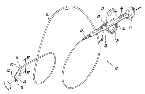
A directional surgical device 10 is seen in FIG. 1 as having particular use
in connection with an endoscope, gastroscope, colonoscope or other elongated
flexible
surgical appliance. In the illustrated embodiment of the invention, the device
10 is a
biopsy forceps tool, although any small endoscopic or similar type of
instrument may find
advantageous utility according to this invention. The directional surgical
device 10
includes remotely actuatable forceps jaws 12 hingedly mounted at the distal
end of a
sheathed elongate tubular member 14.The tubular member 14 is connected at its
proximal
end to an instrument control handle 20. The control handle is conventional in
all respects
and is commercially available from numerous suppliers.
Slidably mounted on the tubular member 14 is a relatively stiff sheath 16
having a length which is slightly shorter than the length of the tubular
member 14, the
purpose of which will be further explained below. The overall length of the
device 10
will vary according to the particular surgical tool and the particular body
insertion tube
for which it is intended. In the presently described embodiment, the overall
length is
about 180 centimeters.
A fitting 17 is attached to the proximal end of the sheath 16 for providing
a gripping or holding point by which to manipulate the relative axial position
of the sheath
CA 02285743 1999-10-08
7
16 with respect to the tubular member 14. The fitting 17 is preferably
removably but
firmly connectable to the control handle 20, such as by frictional engagement
of mating
parts, by mating Luertype connector parts, or by any other known mechanism.
The control handle 20 includes finger rings 22, 23 integrally molded with
a generally cylindrical housing 24 and an axially slidable control shaft 26
passing through
the housing 24 for operation of the forceps jaws 12, the shaft 26 having a
thumb ring 27
at its proximal end. The proximal end of the tubular member 14 is fixedly
connected to
the distal portion of the control shaft 26. In conventional fashion, a pull or
control wire
30 (see FIG. 2) passes through a central lumen 32 within the tubular member
14, and is
connected at its distal end to the proximal ends of the forceps jaws 12, and
at its proximal
end to a screw clamp 28 or other securing mechanism which is integrally formed
with or
otherwise part of the housing 24 of the control handle 20. The forceps jaws 12
are, in
turn, hingedly connected to a forceps jaw mounting body 29 which is rigidly
connected
to the end of the tubular member 14.
By the just-described construction, which is illustrative only, and in a
manner extremely well known to those of ordinary skill in the art, relative
axial movement
of the pull wire with respect to the tubular member 14, by moving the thumb
ring 27
proximally and distally with respect to the finger rings 22, 23, respectively,
causes the
forceps jaws 12
to open and close. It will be readily understood by those of ordinary skill in
the art that
numerous other instrument actuation mechanisms may be employed in other
embodiments
of the invention. The invention does not reside in the use of any particular
instrument or
actuation method, but instead concerns the nature, construction and use of the
tubular
member 14 and the longitudinally slidable sheath 16 thereover, as will be
explained in
greater detail below.
Moreover, the control handle 20 may include an electrical connector 25 or
other conductive attachment device for providing surgically useful electrical
energy, such
as low or high voltage direct current or alternating current, or radio-
frequency (rf) or
microwave energy, or any other therapeutic energy, from an external source of
such
energy to the particular surgical instrument mounted on the distal end of the
tubular
member 14. Other such surgical instruments might not include any moving parts,
and
therefore would not require the particular type of actuating handle described
above in
connection with the presently described embodiment.
CA 02285743 1999-10-08
8
In still other cases, the surgical instrument might not even be mounted on
the tubular member 14, and may simply be insertable into the tubular member 14
after
the distal end portion of the tubular member 14 has been appropriately
positioned by the
device operator. According to the requirements of still other embodiments, one
or more
fluid flow paths, with associated fluid flow controls, may be provided in a
suitable control
handle in accordance with the invention. Some examples of surgical instruments
which
may be constructed according to the principles of the invention are
sclerotherapy needles,
hemostasis probes, electrosurgical needles and other electrodes, infusion or
aspiration or
biopsy needles, graspers, scissors or other cutters, cauterization snares or
probes, laser
fiber optics, etc., without limitation.
The tubular portion 14 may be rotatable about its own longitudinal axis, as
shown by the arrows in FIG. 1.
As illustrated in FIG. 6, the sheathed tubular member 14 is insertable
through an instrument channel of an endoscope or other body insertion tube 40
which is
conventionally also provided with a fiber-optic illumination source, a fiber-
optic image
system including a viewing lens at the insertion tube's distal end, and some
steering
mechanism such as tensioning cables for controlling the orientation of the
distal end of the
insertion tube 40. All of the mechanical and functional details of the
insertion tube 40 are
entirely conventional in this described embodiment of the invention.
As seen in cross section in FIG. 2, the outer, relatively stiff sheath 16
closely houses the elongate tubular member 14 which, in the presently
described
embodiment, is a polytetrafluoroethylene (PTFE) jacketed (jacket: ref. no. 34)
0.016 inch
diameter 302/304 stainless steel spring temper wire coil 35. Torque
transmitting
capability may be provided to the wire coil by, for example, joining (e.g., by
spot-welding) adjacent coils at given
coil intervals, such as every third coil or the like. Alternatively, other
tubular
constructions may be employed, such as braided tube constructions, which have
good
torque transmission characteristics.
The control wire 30 is also stainless steel in this embodiment of the
invention.
The sheath 16 preferably comprises an extruded tube made of
polyetheretherketone (PEEK) resin having an inside diameter of about 0.081
inch and
CA 02285743 1999-10-08
9
tubing wall thickness of about 0.005 inch. A preferred PEEK material is
VICTREX
450P, available from ICI Americas, Inc., of Wilmington, Delaware. Other
suitable
materials for the sheath 16 include TECOPLASTO Op-570-341 resin available
from
Thermedics, Inc., of Woburn, Massachusetts, and PEBAXO polyether block
amidethermoplastic elastomers suitable for extrusion molding applications,
available from
Atochem North America, Plastics Additives Division, of Cleveland, Ohio. The
sheath 16
and the PTFE jacketed coil 35 forming the tubular member 14 have such surface
lubricity
characteristics that the tubular member 14 relatively easily slides proximally
and distally
within the sheath 16, which relative ease of sliding motion is an important
feature of the
invention.
Referring to FIGS. 1 and 3-5, the tubular member 14 is shown as being
provided with a first, proximal bend 50 and a second, distal bend 52 in the
same angular
direction and plane as the proximal bend 50. It is expected by the inventors
that the
optimum angles and positions of these bends 50, 52 relative to the surgical
tool will vary
according to the different uses of particular surgical instruments. However, a
presently
preferred embodiment includes a distal bend 52 located approximately one
centimeter
proximal of the surgical instrument's tip, with the proximal bend 50 located
about four
centimeters proximal of the distal bend 52. The distal bend angle a is
preferably in the
range of about 25 to 60, and the proximal bend angle 0 is preferably in
the range of
about 15 to 45 . The tubular member 14 assumes the doubly bent shape
illustrated in
FIG. 3 only when both the distal bend 52 and proximal bend 50 have been
ejected from
the distal end 55 of the sheath 16.
In the relative axial positions of the components shown in FIG. 4, the distal
bend 52 is present but the proximal bend 50 is not, the tubular member 14
having been
straightened by distal advancement (in the direction of the arrow) of the
relatively stiff
sheath 16. In many particular applications, the operator will elect to extend
only the distal
bend 52 beyond the distal end of the endoscope, while maintaining the proximal
bend 50
within a curved end portion of the scope, either inside or out of the sheath
16, as will be
explained further below.
By continued distal advancement of the sheath 16 over the tubular member
14, both the proximal bend 50 and the distal bend 52 are straightened within
the sheath
16 (see FIG. 5). The physical characteristic of the sheath 16 that it is
sufficiently flexible
to pass inside the curved instrument channel of an endoscope, yet sufficiently
stiff to
CA 02285743 1999-10-08
straighten the bends placed in the tubular member 14, is an important feature
of the
present invention.
It will be understood that other embodiments of the invention be include
elongate tubular members having more than, or less than, two bends in their
distal end
5 portions. For example, certain surgical tools may be most advantageously
positioned at
a known, specific angle. For applications requiring the greatest degree of
angular
accuracy, a single bend may be preferable to two or more bends. For certain
other
applications, a plurality of separate bends may be useful in permitting the
operator to
select the particular oblique angle of approach within a wider range of
options, depending
10 upon the number of curves ejected from the distal end of the sheath.
Now turning to FIG. 9, there is shown a prior art device aimed at solving
many of the same problems addressed by the present invention, which device is
described
in detail in U.S. Patent No. 5,386,818. That device comprises a tubular membei
90
having a distal end portion 94 provided with a spring bias or memory tending
to form the
distal end portion into an arcuate configuration, e.g., a substantially U-
shaped
configuration. The degree of bending of the distal end portion 94 of the
tubular member
90 is determined bycontrolling the degree of ejection of the distal end
portion 94 from the
biopsy channel of an endoscope 92. The more tubular member 90 is pushed in the
distal
direction, the greater the angle that a tip 96 of the tubular member 90 bears
with respect
to a longitudinal axis of the biopsy channel. Upon the attainment of a desired
angle of
approach, an elongate flexible endoscopic instrument is slidably inserted
through the
tubular member 90 so that an operative tip 98 at a distal end of the
instrument projects
outwardly from distal end portion 94. Thus, tubular member 90 serves as an
instrument
guide for controlling the orientation of the operative tip 98 with respect to
the endoscopic
insertion tube 92.
As further seen in FIG. 9, the prior art device suffers several disadvantages
in use. As shown in dashed lines 91, the endoscope operator's distal field of
vision is
typically on the order of 90 , centered along the scope's longitudinal axis.
Upon pushing
the pre-curved tubular guide member 90 distal of the end of the endoscope's
biopsy
channel, the tubular member tip 96 quickly passes out of the operator's field
of view.
Merely advancing the tubular member 90 further distally does not solve this
problem, for
while the tubular member tip 96 may thus come back into view, it is only
positionable in
its fully U-shaped configuration, and cannot conveniently be used to deliver
the instrument
CA 02285743 1999-10-08
11
operative tip 98 to the wall of the tract organ at an oblique angle.
Furthermore, since the
curving action of the distal end portion 94 occurs as soon as the portion 94
begins to
emerge from the biopsy channel, this feature of the prior art device may only
be useful
at surgical sites permitting access by the full outside diameter of the
endoscope.
In contrast, referring to FIGS. 6, 7 and 10, the improved surgical
instrument assembly of the present invention allows an oblique angle approach
to tract
organ surgical sites which are too small to be conveniently accessible by the
full outside
diameter of the endoscope, and with the surgical instrument tip always
maintained in the
operator's field of view. FIGS. 6 and 7 illustrate particular steps in the
diagnostic or
treatment procedure, as now explained. An endoscope or body insertion tube 40
having
a longitudinal instrument channel therethrough has been provided. A sheathed
elongate
tubular member 14 has been inserted into the biopsy or instrument channel,
with the
sheath 16 advanced distally so that the sheath 16 fully houses the entire
distal end portion
68 of the tubular member 14, including an operative tip 69 mounted on the
distal end of
the tubular member (see FIG. 6). A distal end segment of the endoscope 40 has
been
inserted into a patient's esophagus 70. The sheathed tubular member 14 has
been pushed
in a distal direction to eject at least a part of the sheathed distal end
portion 68 thereof
from the instrument channel, in the patient. Finally, as shown in FIG. 7,
while
maintaining the distal end of the sheathed tubular member 14 within the
operator's field
of view, the tubular member 14 has been advanced distally with respect to the
sheath 16
(by moving the sheath 16 proximally as shown by the arrows 72,73), thereby
selectively
causing both curved portions 50, 52 of the tubular member 14 to be ejected
distally from
the sheath 16 and thereby causing the end of the tubular member 14 to deflect
a
predetermined angle with respect to the longitudinal axis of the scope under
the action of
the tubular member's resilient bias force. Subsequent steps (not shown)
include operating
on internal tissues of the patient with the operative tip 69.
Numerous variations of this procedure are possible, all being well within
the scope of the invention. Depending upon the nature of the surgical
procedure, the
particular body insertion tube and the surgical instrument involved, the order
of steps by
which the final operative positioned is achieved will vary greatly. For
example, the
sheathed tubular member may be inserted into an already-positioned endoscope.
In some
cases where the surgical instrument is removably insertable into the tubular
member, the
sequential time or step at which the instrument is inserted into the tubular
member will
CA 02285743 1999-10-08
12
be a matter of operator's choice. The variations are as numerous as there are
different
preferences for performing different procedures using, e. g. , endoscopes,
bronchoscopes,
colonoscopes, gastroscopes,
uteroscopes, laparoscopes and the like.
As shown in FIG. 10, the operative ti.o 69 r.emains well within the
operator's field of view, both when inside the sheath 16 and when in its
angled
configuration for approaching the surgical site. With a suitably long device,
the sheathed
tubular member 14 may be extended a considerable distance distally beyond the
end of the
body insertion tube 40, before withdrawing the sheath 16 to angle the
operative tip 69.
Since the outside diameter of the sheath 16 is so much less (a preferred
device according
to the invention fits within a 5 French instrument channel) than that of the
body insertion
tube or endoscope 40, the operator may deliver the operative tip 69 to
surgical sites which
might be otherwise inaccessible to the endoscope, or to the prior art device
described and
illustrated in U.S.Patent No. 5,386,818.
A further feature of the invention is the ability, provided to the endoscope
operator, to position the plane of the proximal bend 50 and distal bend 52 in
a desired
angular position about the longitudinal axis of a steerable or deflectable
endoscope or
similar device having a controllable, deflectable end portion. In such an
endoscope 80 as
is illustrated in FIG. 8, the distal end portion 82 thereof may be steered or
deflected to
navigate a corner 83 or bend in the patient's internal anatomy, as is
conventionally done.
Upon achieving the illustrated configuration of the scope 80, the operator may
then
withdraw proximally the sheath 84 from the distal end portion 86 of the
tubular member
87 so as to unsheath the distal bend 88 and the proximal bend 89 therein. The
bias forces
in the tubular member 87 as a result of the bends 88, 89 therein, coupled with
the
lubricous characteristics of the PTFE jacket, permit the device to rotate on
its own axis
toward the most relaxed angular orientation, in which the plane of the bends
88, 89
coincides with the plane of the curved endoscope distal end portion 82, which
planar
orientation is known to the operator. The operative tip 85 may then be
advanced distally
and ejected out of the instrument channel, or else, once properly angularly
oriented, the
tubular member distal end portion 86 may be resheathed and advanced to a
surgical site
in the operator's field of view in the sheathed condition. In a situation
where the surgical
site is close to the endoscope's distal end, the operator may simply extend
the distal end
portion 86 only so far as to eject the distal bend 88 from the instrument
channel, while
CA 02285743 1999-10-08
13
maintaining the proximal bend 89 within the curved end portion of the
endoscope. Such
use also provides rotational angular control and predictability of operative
tip direction for
the operator. In this way, additional control over the position of the distal
end of the
surgical device of the present invention is achieved.
Referring, finally, to FIG. 11, an alternative embodiment of the invention
is illustrated and now described. In this embodiment, which may be
particularly
advantageous for certain surgical procedures, at least one angular bend is
formed in a
distal end portion of the sheath itself, while the flexible tubular member
carrying or
delivering the operative tip or other surgical instrument to the surgical site
is generally
straight, in the absence of any external forces. The presently preferred
version of this
embodiment includes two bends. The sheath is maintained in a generally
straightened
condition while inside the instrument channel of the endoscope or similar body
insertion
tube, by the straightening forces applied thereto by the walls of the
instrument channel.
Upon further distal advancement of the sheath in the scope's instrument
channel and
beyond the distal end of the endoscope, the sheath will selectively assume
either its singly
bent or doubly bent configuration depending upon how far out of the instrument
channel
the sheath is advanced. Upon the operator's positioning of the distal end of
the sheath in
the desired position and at the desired oblique angle of
approach to the surgical site, the slidably housed tubular member may be
advanced
distally with respect to the sheath in order to advance the operative tip
thereon or therein
to the site.
As was the case for the previously described embodiments, the sheath of
FIG. 11 may be positioned so that the proximal bend is positioned within a
curved end
portion of the endoscope or similar body insertion tube, with the effect that
the proximal
bend will tend to follow the curve of the scope's distal end portion. In this
manner, the
distal bend of the sheath will be predictably oriented in a direction which is
controllable
by the operator.
It is to be understood that the drawings and descriptions herein are
preferred by way of example to facilitate comprehension of the invention and
should not
be
construed to limit the scope thereof.
While the invention has been particularly shown and described with
reference to the preferred embodiments thereof, it will be understood by those
skilled
= CA 02285743 1999-10-08
14
changes in form and detail may be made departing from the spirit and scope of
in the art
that various therein without the invention.