Note: Descriptions are shown in the official language in which they were submitted.
CA 02285762 2004-O1-19
7690'7-17
SMART BINARY SWITCH FOR USE WITH AN
ELECTRONIC PATIENT MONITOR
RELATED APPLICATIONS
This application claims priority from U.S. patent number 6 , 3 0 7 , 4 7 6 .
FIELD OF THE INVENTION
This invention relates generally to monitoring systems and more particularly
concerns
devices and systems used to monitor seated or lying patients in homes or in
medical
environments such as hospitals, institutions, and other care-giving
environments.
BACI~OROUND OF THE INVENTION
It is well documented that certain individuals, including elderly and post-
surgical
patients, are at a heightened risk of falling. There are many reasons for this
but, broadly
speaking, these individuals are often afflicted by gait and balance disorders,
weakness,
dizziness, confusion, visual impairment, and postural hypotension (i.e., a
sudden drop in
blood pressure that causes dizziness and fainting), all of which are
recognized as potential
contributors to a fall. Additionally, cognitive and functional impairment, and
sedating and
psychoactive medications are also well recognized risk factors
A fall places the patient at risk of various injuries including sprains,
fractures, and
broken bones - injuries which in some cases can be severe enough to eventually
lead to a
fatality. Of course, those most susceptible to falls are often those in the
poorest general health
and least likely to recover quickly from their injuries. In addition to the
obvious physiological
consequences of fall-related injuries, there are also a variety of adverse
economic and legal
consequences that include the actual cost of treating the victim and, in some
cases, caretaker
liability issues.
In the past, it has been commonplace to treat patients that are prone to
falling by limiting
their mobility through the use of restraints, the underlying theory being that
if the patient is not
free to move about, he or she will not be as likely to fall. However, research
has shown that
restraint-based patient treatment strategies are often more harmful than
beneficial and should
generally be avoided - the emphasis today being on the promotion of mobility
rather than
immobility. Among the more successful mobility-based strategies for fall
prevention include
interventions to improve patient strength and functional status, reduction of
environmental
hazards, and staff identification and monitoring of high-risk hospital
patients and nursing home
residents.
Of course, monitoring high-risk patients, as effective as that care strategy
might appear
to be in theory, suffers from the obvious practical disadvantage of requiring
additional staff if
76907-17
CA 02285762 2004-O1-19
the monitoring is to be in the form of direct observation. Thus, the trend in
patient monitoring
has been toward the use of electrical devices to signal changes in a patient's
circumstance to a
care-giver who might be located either nearby or remotely at a central
monitoring facility, such
as a nurse's station. The obvious advantage of an electronic monitoring
arrangement is that it
frees the care-giver to pursue other tasks away from the patient.
Additionally, when the
monitoring is done at a central facility a single nurse can monitor multiple
patients which can
result in decreased staffing requirements.
Generally speaking, electronic monitors work by first sensing an initial
status of a
patient, and then generating a signal when that status changes, e.g., he or
she has sat up in bed,
left the bed, risen from a chair or toilet seat, etc., any of which situations
could pose a potential
cause for concern in the case of an at-risk patient. Electronic bed and chair
monitors typically
use a pressure sensitive switch in combination with a separate monitor /
microprocessor. In a
common arrangement, a patient's weight resting on a pressure sensitive mat
(i.e., a "sensing"
mat) completes an electrical circuit, thereby signaling the presence of the
patient to the
microprocessor. When the weight is removed from the pressure sensitive switch,
the electrical
circuit is interrupted, which fact is sensed by the microprocessor. The logic
that drives the
monitor is typically programmed to respond to the now-opened circuit by
triggering some sort
of alarm - either electronically (e.g., to the nursing station via a
conventional nurse call
system) or audibly (via a built-in siren). Some examples of monitoring devices
that operate in
this general fashion may be found in U.S. Letters Patent Nos. 4,179,692,
4,295,133.
4,700,180, 5,633,627, and 5,640,145.
Additionally, many variations of this arrangement are possible and electronic
monitoring devices that track changes in other patient variables (e.g.,
wetness / enuresis,
patient activity, etc.) are available for some applications.
However, present mats and other sensing devices for use in patient monitoring
suffer
from a number of disadvantages. For example, a problem with present mats and
monitoring
systems is that they do not provide a means for the monitor to identify the
particular type of mat
attached thereto. A monitor manufacturer might wish to do this for any number
of reasons.
For example, providers of medical equipment can be held liable for damages
caused to a patient
because of a failure in their monitoring system, a fact that argues for a
method of making
certain that mat attached thereto is fully compatible with the monitor.
Additionally, a monitor manufacturer would like to have some assurance that
the mats
that are attached to his or her unit meet basic standards of quality, as the
monitor could blamed
- at least initially - for a failure in a mat that allows a patient to leave
the bed unnoticed.
Further, for quality control purposes, it might be desired in some
applications to be able to
track the length of time that a particular mat has been in place, thereby
assisting the health care
provider in identifying mats that might be nearing the end of their useful
lives.
CA 02285762 1999-10-12
BEDCHK-67034
Still further, it would be useful in some circumstances to be able to
automatically
identify whether the switch that is connected to the monitor is of the proper
type for this
application. For example, pressure-sensitive chair monitors should not be used
to sense
wetness in beds and vise versa. Where the possibility exists that the mats
designed for
different applications might be interchanged, it would be of benefit to the
manufacturer of the
mats and / or electronic monitors to be able to recognize that fact and notify
the caregiver
accordingly.
Finally, it is a problem with present mats and monitoring systems that they do
not
provide any means of automatically determining whether or not the electrical
connection
between the monitor and mat is sound. It is well known to those skilled in the
art that the
wiring that interconnects the mat and monitor is exposed to various stresses
that can result in
impaired functionality or even equipment failure. For example, if the
interconnecting wire is
not making continuous contact at one end or the other, the monitor will see an
"open" circuit,
whether or not the patient is actually present in the bed. To test the
interconnection, it is
necessary to put weight on the mat, which would usually be done by placing the
patient upon
it, thereby closing the detection circuit which event can then be sensed by
the monitor. Where
there is problem in the connection, the patient will have to be roused out of
bed so that the mat
can be changed. This disturbs the patient and takes additional caregiver time.
It would be a
tremendous advantage in some situations to be able to have the electronic
monitor quickly and
automatically indicate to the caregiver when there is there is no electrical
continuity between the
mat and the monitor.
Heretofore, as is well known in the bed monitor arts, there has been a need
for an
invention to address and solve the above-described problems. Accordingly, it
should now be
recognized, as was recognized by the present inventors, that there exists, and
has existed for
some time, a very real need for a smart mat and monitoring system that would
address and
solve the above-described problems.
Before proceeding to a description of the present invention, however, it
should be noted
and remembered that the description of the invention which follows, together
with the
accompanying drawings, should not be construed as limiting the invention to
the examples (or
preferred embodiments) shown and described. This is so because those skilled
in the art to
which the invention pertains will be able to devise other forms of this
invention within the
ambit of the appended claims.
3
CA 02285762 2004-O1-19
76907-17
SUMMARY OF THE INVENTION
In accordance with a first aspect of the instant
invention, there is provided a binary switch-type device
(e. g., a "mat") for use in patient monitoring situations
which contains, in addition to a conventional patient
detection circuit, identification circuitry that can be read
by an attached electronic monitor in order to determine the
type of mat that is attached thereto (i.e., a "smart" mat).
Additionally, and by way of example only, the identification
circuitry also provides a means for the electronic monitor
to recognize certain types of electrical interconnection
failures, to identify mats that are nearing the end of their
useful lives, to warn the caregiver when a mat that is
designed for one operating environment/application is used
in another, etc.
In another aspect of the invention, there is
provided a device for detecting a presence or an absence of
a patient, comprising: (a) a binary switch, the binary
switch being responsive to at least two conditions, (al) a
first condition corresponding to the presence of the patient
on the binary switch, and, (a2) a second condition
corresponding to the absence of the patient from the binary
switch; (b) a validation circuit; (c) a first electrical
connection, the first electrical connection being in
electrical communication with the binary switch; (d) a
second electrical connection, the second electrical
connection being in electrical communication with the
validation circuit; and, (e) an electronic patient monitor
in electrical communication with the first electrical
connection and the second electrical connection, wherein,
(e1) the electronic patient monitor is responsive to at
least the binary switch and the validation circuit, and,
4
CA 02285762 2004-O1-19
76907-17
(e2) the electronic patient monitor has a microprocessor in
electrical communication with at least the second electrical
connection, the microprocessor at least for reading the
validation circuit and being responsive thereto.
In yet another aspect of the invention, there is
provided a method by which an electronic patient monitor may
identify a patient sensor attached thereto, wherein is
provided the aforementioned device, the microprocessor
programmed to perform the steps of: (a) causing a signal to
be generated; (b) transmitting the signal to the validation
circuit; (c) sensing a response to the signal from the
validation circuit; (d) comparing the sensed response with
at least one predetermined response; and, causing the
electronic monitor to indicate an alarm condition if the
sensed response does not at least approximately correspond
to at least one of the at least one predetermined responses.
In a further aspect of the invention, there is
provided a method identifying a patient sensor, wherein is
provided an electronic patient monitor in electrical
communication with a binary switch, the binary switch having
a validation circuit associated therewith, comprising the
steps of: (a) causing a signal to be generated within the
electronic patient monitor; (b) transmitting the signal to
the validation circuit; (c) sensing a response to the signal
from said validation circuit; (d) comparing the sensed
response with at least one predetermined response; and, (e)
causing the electronic monitor to indicate an alarm
condition if the sensed response does not at least
approximately correspond to at least one of the at least one
predetermined responses.
In a still further aspect of the invention, there
is provided a device for sensing a condition of a patient,
4a
CA 02285762 2004-O1-19
76907-17
comprising: (a) a binary switch, the binary switch being
responsive to at least two conditions, (al) a first
condition corresponding to an initial state of the patient,
and, (a2) a second condition corresponding to a changed
state of the patient; (b) a validation circuit; (c) a first
electrical connection, the first electrical connection being
in electrical communication with the binary switch; (d) a
second electrical connection, the second electrical
connection being in electrical communication with the
validation circuit; and (e) an electronic patient monitor in
electrical communication with the first electrical
connection and the second electrical connection, wherein,
(e1) the electronic patient monitor is responsive to at
least the binary switch and the validation circuit, and,
(e2) the electronic patient monitor has a microprocessor in
electrical communication with at least the second electrical
connection, the microprocessor at least for reading the
validation circuit and being responsive thereto.
In the preferred embodiment, unused electrical
wires in the connecting line between the binary switch and
monitor are used to allow access by a microprocessor within
the electronic monitor to an integrity/identification/
verification/validation circuit which is preferably made a
part of the mat. This circuit might take many forms
including simple resister or capacitor circuits, or more
complex circuits that might involve use of an integrated
circuit. In any case the ultimate goal is the same:
identification and/or recognition by the monitor of the mat
that has been attached thereto. This identification might
take place at any time, but preferably will take place at
Least when the unit is powered up or reset. It might also
be performed at scheduled time intervals or random times,
depending the needs of the particular application.
4b
CA 02285762 2004-O1-19
76907-17
The foregoing has outlined in broad terms the more
important features of the invention disclosed herein so that
the detailed description that follows may be more clearly
understood, and so that the contribution of the instant
inventor to the art may be better appreciated. The instant
invention is not to be limited in its application to the
details of the construction and to the arrangements of the
components set forth in the following description or
illustrated in the drawings. Rather, the invention is
capable of other embodiments and of being practiced and
carried out in various other ways not specifically
enumerated herein. Further, the disclosure that follows is
intended to cover all alternatives, modifications and
equivalents as may be included within the spirit and scope
of the invention as defined by the appended claims.
Finally, it should be understood that the phraseology and
terminology employed herein are for the purpose of
description and should not be regarded as limiting, unless
the specification specifically so limits the invention.
While the instant invention will be described in
connection with a preferred embodiment, it will be
understood that it is not intended to limit the invention to
that embodiment. On the contrary, it is intended to cover
all alternatives, modifications and equivalents as may be
included within the spirit and scope of the invention as
defined by the appended claims.
4c
CA 02285762 1999-10-12
BEDCHK-67034
BRIEF DESCRIPTION OF THE DRAWINGS
Other objects and advantages of the invention will become apparent upon
reading the
following detailed description and upon reference to the drawings in which:
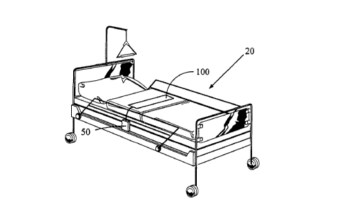
Figure 1 illustrates the general environment of the instant invention.
Figure 2 contains a schematic diagram of two preferred embodiments of the
instant
invention: Figure 2A illustrates a mat which incorporates the validation
circuit internally and
Figure 2B illustrates a mat in which the validation circuit is external.
Figure 3 contains a flow chart that illustrates some of the principal steps in
the preferred
electronic monitor control logic.
5
CA 02285762 1999-10-12
BEDCHK-67034
DETAILED DESCRIPTION OF THE INVENTION
General Background
According to a preferred aspect of the instant invention, there is provided a
patient
sensor for use with an electronic bed patient monitor, wherein the sensor
incorporates
additional circuitry which is accessible by the electronic monitor and that
can be read thereby.
In more particular, two preferred uses of the sensor circuitry include the
identification by the
monitor of the type of mat connected thereto and the diagnosis of some
connectivity-type
problems.
Turning first to Figure 1 wherein the general environment of the instant
invention is
illustrated, in a typical arrangement a sensing mat 100 is placed on a
hospital bed 20 where it
will lie beneath a weight-bearing portion of the reclining patient's body,
usually the buttocks
and / or shoulders. Generally speaking, the mat 100 / monitor 50 combination
works as
follows. When a patient is placed atop the mat 100, the patient's weight
compresses the mat
100 and closes an electrical circuit 215, which closure is sensed by the
attached electronic
patient monitor 50. When the patient attempts to leave the bed, weight is
removed from the
sensing mat 100, thereby breaking the electrical circuit 215, which
interruption is sensed by
the attached electronic patient monitor 50. The patient monitor then signals
the caregiver per its
pre-programmed instructions. Note that additional electronic connections not
pictured in this
figure might include a monitor 50 to nurse call station connection, a monitor
50 to computer
connection, and a monitor power cord - although the monitor 50 can certainly
be configured
to be battery operated.
Preferred Hardware Arrangement
A first preferred embodiment of the instant mat 100 and an associated
electronic patient
monitor 50 are illustrated in Figure 2A. In that figure, the patient monitor
50 is shown as
including a microprocessor 210, which microprocessor controls the sensing and
response of
the monitor 50 to changes in the patient detection circuit 215. As was
explained previously,
the patient detection circuit 215 preferably consists of an electronic circuit
that changes states
when a patient's weight is placed upon the mat 100, e.g. it might change from
an "open"
circuit to a "closed" circuit or vice versa. More generally, this circuit
might be continuously
responsive to any other environmental condition such as patient activity,
wetness, etc.
However, the heart of the instant invention is the validation circuit 220,
which is preferably
made to be a part of the sensing mat 100 as indicated in Figure 2A.
As is illustrated in Figure 2A, in the preferred embodiment the mat 100 and
monitor
50 are interconnected by a single RJ-11 type electrical connector 225 through
which pass four
electrical lines: one pair 230 in electrical communication with the patient
detection circuit 215
and the other pair 235 in electrical communication with the validation circuit
220. Note that
6
CA 02285762 2004-O1-19
76907-17
this is just a preferred embodiment and that other arrangements might include
more than four
electrical lines (or fewer) and it is well within the ability of one skilled
in the art to devise such
alternative arrangements. Additionally, connector 225 could be separated into
two separate
connectors without changing the spirit of the instant invention and it would
be well within the
ability of one skilled in the art to modify the monitor 50 accordingly.
Microprocessor 210 reads electrical lines 230 through detection port 286 and
responds to changes in that circuit according to its pre-assigned
instructions. Typically, the
microprocessor 210 will be programmed to initiate some sort of alarm if a
change (e.g.; a
discontinuity) is detected in the patient detection circuit 215, which change
would most likely
indicate that the patient has left the bed 20. The alarm triggered by the
monitor 50 might be
either a local alarm (e.g., generated within the monitor 50 itself) or a
remote alarm in the hall or
at a nurses station. This portion of the mat 100 / monitor 50 combination is
of a conventional
design.
The particular patient monitor circuit 215 which used within the mat 100 is
immaterial
to the operation of this invention, although it must generally be in the form
of a binary switch, a
binary switch or sensor being one that is capable of sensing at least two
conditions and
responding to same via distinct electronic signals. Although a pressure
sensitive switch is the
binary switch of choice for use in the preferred embodiment, other types of
switches could
work as well. Examples of binary switches / mats which would be suitable for
use with the
instant invention include those found in U.S. Letters Patent 5,623,760,
5,554,835, 4,484.043,
4,545,910, and US 5,945,914, for a toilet seat monitor. So,
for purposes of this disclosure, the term "mat" will be
taken to mean conventional bed and chair mats, as well as
other sorts of sensors which detect patient conditions and
are useful in patient monitoring.
However, of most interest for purposes of the instant invention is the
validation circuit
220 and its many applications in patient monitoring. Turning again to Figure
2A, in this
figure the basic electronic interconnections for a mat 100 that has been
equipped with the
validation circuit 220 of the instant invention have been illustrated. Two
unused lines 235 that
are normally available within an RJ-11-type connector 225 are preferably used
to establish an
electrical connection between the monitor CPU 210 and the validation circuit
220. The
monitor 50 senses the state of validation circuit 220 by way of validation
port 287.
Additionally, provision has been made in the preferred embodiment for
inclusion of a date /
time chip 295 which can be read by the CPU 210 and used to"date stamp" various
events that
are sensed thereby. Details of one possible hardware arrangement that would
accommodate
this sort of operation may be found in U.S. patent
No. 6,441,742, which is a continuation
7
7 6 9 0 7 -17 ~ 02285762 2004-O1-19
of US 6, 111, 509.
Note that, although the preferred embodiment of the instant invention is
designed to be
used with an electronic patient monitor containing a microprocessor, that is
not an essential
element of the instant invention and it is certainly possible and within the
ability of one of
ordinary skill in the art to construct a simple analog patient monitor that is
responsive to the
patient detection circuit and identification circuits, but which contains no
computer components.
Thus, when the term "electronic patient monitor" is used herein, that term
should be interpreted
in its broadest sense to include both patient monitors that have - and those
that do not have -
controlling microprocessors.
The precise hardware that would be included within the monitor 50 to query the
validation circuit 220 will be a function of the sort of electrical circuit
that has been installed
there: In the simplest situation, the circuit could consist of a simple closed
electrical loop. The
monitor 50 could use this loop to perform a continuity check between the
monitor ~0 and the
mat 100. Then, if no electrical current can be detected through the circuit,
it is likely that the
mat 100 / monitor ~0 connection has been damaged in some way, or that the mat
~0 is not
properly plugged into the monitor. Either way, the caregiver should be
immediately notified so
that corrective action may be taken before the patient is placed on the mat
100. Note that this
continuity test - and the other tests described below - may be performed
independently of
whether a patient is actually present on the mat. This is a significant
advance over the existing
state-of the-art in patient monitors.
By way of a next simple example of a circuit that would be appropriate for use
with the
instant invention, validation circuit 220 might consist of a precision
resistor of, say, 100 ohms
that is placed across the leads 235. The monitor CPU 210 would then cause a
known current
to be applied to the leads 23~ on the monitor end and, thereafter, measure the
resulting voltage
(which is related to the resistance in the validation circuit 220 via a well
known equation).
Then, if the resistance of the circuit as measured at the monitor is not
within, say, 1 % of 100
ohms, the CPU 210 will sound an alarm to notify the caregiver that there is
some problem with
the mat. Obviously, if the measured resistance is too high, that would
indicate a break in the
electrical connection between the monitor 50 and validation circuit 220.
Resistances that
deviate from the expected resistance might indicate physical damage to the
circuit or poor
connectivity between mat 100 and monitor ~0.
In an alternative embodiment, the resister might be chosen in such as way as
to
communicate some information to the monitor. For example, a 30 ohm resister
might be used
with mats having a 30-day useful life, and a 100 ohm resister with a 100 day
mat, etc.
Obviously, this sort of arrangement would make it possible for an
appropriately designed
s
CA 02285762 1999-10-12
BEDCHK-67034
monitor 50 to track the usage time of a mat that has been continuously
connected thereto and
signal when the mat 100 nears the end of its recommend period of use.
Alternatively, the validation circuit 220 might instead be formed from a
capacitor, an
inductor, or some combination of one or more of each component. In this case,
the CPU 10
can sense the presence of the validation circuit 220 by testing the reactance
of the circuit
formed thereby. As was described previously, if the measured reactance of the
circuit does not
match a predetermined value - which might indicate a poor electrical
connection or that a mat
of the improper type has been connected to the monitor 50 - an alarm would be
sounded.
As a final example of the sort of circuit that would be appropriate for use
with the
instant invention, the inventors contemplate that it could prove to be useful
in some applications
to install a ROM chip, or even a flash RAM chip, within the mat 100. The ROM
chip could
contain and dispense a wide variety of information including, by way of
example, a mat serial
number, a mat manufacture date / lot number, and various other parameters that
would define
the sorts of uses to which this mat might be put. Flash RAM, on the other
hand, could contain
all of the foregoing and, additionally, values that might be modified by the
monitor 50. One
obvious example of the sort of information that might be placed in flash RAM
would be a
running total of the amount of time that the mat 100 has been in service.
Communications
between the monitor 50 and the chip would preferably be handled via the I2C
communications
protocol which has become the predominant standard for low cost inter-chip
communications
(i.e., "Inter-IC", which is a standard means of providing a two-wire
communication link
between integrated circuits). Detailed information on the chip and the I2C
protocol may be
found in the Microchip Nonvolatile Memory Products databook.
As illustrated in Figure 2A, the validation circuit 220 is preferably made a
part of -
and included within - the mat 100 (e.g., Figure 2A). However, it is
anticipated by the
instant inventors that the validation circuit 220 could be incorporated within
the RJ-11-type
connector 225 for some applications or even designed to be a separate module
which is
positioned between the mat 100 and the monitor 50 (e.g., Figure 2B, part 221).
In any case,
the physical location of the validation circuit is immaterial to the instant
application, except
that its functionality may vary somewhat depending upon where it is positioned
with respect
to the mat 100.
General Method of Operation
In normal operation - and if the mat 100 is used with a patient monitor 50
having a
microprocessor - the principle steps in the monitor's logic flow are generally
as indicated in
9
CA 02285762 1999-10-12
BEDCHK-67034
Figure 3. Note that, depending on the exact model of electronic monitor, there
will be a
variety of switches on its exterior that allow the attendant to arm or disarm
the device,
temporarily suspend its operation, change its response parameters or hold and
delay~times,
etc. Although these sorts of activities are not considered within Figure 3,
those skilled in the
art will understand how the figure could easily be modified to illustrate
them.
After the monitor 50 is first powered-up 305 (or reset) it will typically
perform some
basic hardware diagnostics and initialize local program variables (steps 310
and 315). Next,
the monitor 50 will preferably perform an initial query of the validation
circuit (320) using
methods such as those suggested previously. In its broadest sense, this query
may be
thought of as a "signal" that is transmitted to the validation circuit 320.
The signal might be
as simple as the application of a specific voltage across the electrical lines
235, or it could be
the more complicated signaling scheme required by the I2C protocol.
Needless to say, the precise type of "query" employed by the monitor 50 will
depend
on - and need to be matched to - the general nature of the validation circuit
220. From the
initial query, the CPU 210 will obtain a test result (320) of some sort. By
comparing (step
325) the results of the query 320 with expected outcomes that have been
supplied by, for
example, the manufacturer, the monitor will be able to identify certain kinds
of electrical
problems and distinguish some sorts mats from others. For those instances when
the result
of the query is not as expected, an alarm will preferably be sounded 330. The
alarm might be
limited to the loudspeaker of the local monitor 50 or transmitted further to
the nurses station.
Assuming that the initial check of the mat 50 yields a favorable result, the
monitor 100
will then normally begin tracking the condition of the patient detection
circuit 215 in the mat
(steps 335 and 340) and will generate a response when the patient circuit 215
is interrupted
(steps 340 and 345). As part of the on-going tracking effort, additional /
intermittent testing
of the validation circuit 320 could be performed (steps 350 and 320) at time
intervals
specified by the user (steps 350 and 355). Although the validation circuit 220
could be
continuously monitored, that would normally not be required and, in the
preferred
embodiment, the mat integrity / validation would be redetermined at intervals
of, say, five
minutes.
CA 02285762 1999-10-12
BEDCHK-67034
Of course, sounding an alarm might not be the end of the matter. In some
cases, the
monitor 50 might be programmed to briefly sound an alarm to simply warn the
caregiver that,
for example, a mat 100 is nearing the end of its useful life and should be
replaced. The alarm
would automatically cease after a relatively short period of time for these
sorts of warnings.
In other cases, a simple "acknowledgement" switch could be provided that would
turn off the
alarm and let the caregiver continue as before using the same equipment. On
the other hand,
when the problem is more serious (e.g., when mat 100 has been placed into an
environment
for which it was not designed) that situation might require the caregiver to
manually override
the alarm, an operation that would preferably be logged within the monitor 50
and / or
transmitted to the central monitoring station. Finally, in some extreme
circumstances the
monitor 50 might disable itself and sound a continuous alarm until the
connected mat 100 is
removed. Circumstances where that might be necessary include instances where
the monitor
has detected a lack of electrical continuity between the monitor 50 and the
mat 100. Clearly,
many variations of this arrangement are possible and have been contemplated by
the instant
inventors.
Conclusions
Although the preceding text has occasionally referred to the electronic
monitor of the
instant invention as a "bed" monitor and the sensing switch a "mat", that was
for purposes of
specificity only and not out of any intention to limit the instant invention
to that one
application. In fact, the potential range of uses of this invention is much
broader than bed-
monitoring alone and might include, for example, use with a chair monitor, a
toilet monitor, or
other patient monitor applications, each of which is configurable as a binary
switch, a binary
switch being one that is capable of sensing at least two conditions and
responding to same via
distinct electronic signals. In the preferred embodiment, those two conditions
would be the
presence of patient and the absence of a patient from a monitored area.
Although a pressure
sensitive switch is the binary switch of choice for use in the preferred
embodiment, other
types of switches could work as well for some applications including, for
example, sensors
that detect moisture. Additionally, it should be noted that the use of the
term "binary" is not
intended to limit the instant invention to use only with sensors that can send
only two signal
types. Instead, binary switch will be used herein in its broadest sense to
refer to any sort
11
CA 02285762 1999-10-12
BEDCHK-67034
sensor that can be utilized to sense the condition or location of a patient,
even if that sensor
can generate a multitude of different signals.
Thus, it is apparent that there has been provided, in accordance with the
invention, a
patient sensor and method of operation of the sensor that fully satisfies the
objects, aims and
advantages set forth above. While the invention has been described in
conjunction with
specific embodiments thereof, it is evident that many alternatives,
modifications and
variations will be apparent to those skilled in the art and in light of the
foregoing description.
Accordingly, it is intended to embrace all such alternatives, modifications
and variations as fall
within the spirit of the appended claims.
12