Note: Descriptions are shown in the official language in which they were submitted.
' - CA 02285774 1999-10-08 '
1
ADZ 2 008
EBS MODULATOR WITH DIRECT ERHAOST CAPABILITY
Background of the Invention
This invention relates to a proportional
modulator for controlling air pressure in a braking system
and particularly to a modulator of simplified design
having direct exhaust capability.
Electropneumatic braking systems (EBS) use a
fluid modulator that converts an electrical signal from an
electronic control unit into a pneumatic signal that
actuates vehicle brakes. A conventional electropneumatic
proportional brake for regulating pressure is shown and
described in U.S. Patent No. 5,123,718, the details of
which are incorporated herein by reference. An electrical
signal is conveyed from a foot pedal and input to an
electronic control unit which provides an electrical
signal to an armature of a solenoid actuator of the
modulator. Energizing the armature controls movement of
a piston extending outwardly from the solenoid valve
assembly. The piston includes a seal that engages a valve
seat formed on a hollow spool valve. Opposite external
end surfaces of the spool valve include seal members, such
as O-rings, that are sealed relative to the modulator
housing in a deactuated position of the spool valve. Thus
in the deactuated position, supply pressure from a source
of pressurized air is communicated to an inlet port of the
modulator and does not reach the brake or delivery port.
Instead, the delivery port remains in communication with
an exhaust port, i.e., the brakes are in a release
position.
A diaphragm includes a pilot passage
therethrough which maintains the delivery port in
communication with a small diameter exhaust port formed in
the modulator housing. More particularly, when deactuated
' ' - CA 02285774 1999-10-08 °
- 2 -
the piston is retracted relative to the solenoid valve.
Thus, the piston is disposed in a normally open position.
In this manner, the delivery port is in communication
through a small diameter passage formed in the hollow
spool valve with the small diameter exhaust port.
During a brake application, a pulse width
modulated electrical signal is provided to the solenoid
armature. This urges the piston to a closed position with
the valve seat on the end of the spool valve. The piston
l0 also moves the spool valve so that the external seal on
the spool valve is opened and supply pressure communicates
therethrough to the delivery port. As will be
appreciated, the diaphragm is also unseated as a result of
the pressure from the supply port. The pressure from the
supply port also communicates through a small diameter
opening through the spool valve. The pressure, in turn,
acts against the piston so that a proportioning action
occurs.
When the brake is released and the piston is
retracted within the armature, the spool valve engages its
seat and pneumatic pressure through the supply port is
terminated. The pressure at the delivery port lifts the
diaphragm valve so that a quick exhaust may be made
through the large diameter exhaust opening in the
modulator housing.
The conventional EBS proportional modulator
assembly described above is relatively complex and has
many components. The diaphragm used as a quick release
also adds an undesired differential across the supply and
delivery ports. In addition, it is desirable to eliminate
the small diameter exhaust port opening through which the
brake port normally communicates through the spool valve.
Accordingly, a need exists for a quick release
valve of an ABS/EBS module that exhausts a large control
volume in a short period of time without adding a
differential across the supply and delivery ports. It is
' ~ ~ ' CA 02285774 1999-10-08 -
- 3 -
desirable that such a valve not be as complex as that
known in the art.
Summary of the Invention
The present invention provides an EBS modulator
having a quick exhaust function with a simplified
structure that eliminates the complexity and cost
associated with prior. arrangements.
According to the present invention, a preferred
modulator includes a housing having a supply port,
delivery port, and an exhaust port communicating with a
valve chamber formed in the housing. A valve member
received in the housing controls flow between the ports
and includes an internal passage dimensioned to provide
quick exhaust capability.
According to another aspect of the invention, an
actuator is responsive to an electrical signal and
cooperates with the valve member for regulating flow
between the ports.
A primary advantage of the present invention is
found in the simplified structure using a reduced number
of valve components.
Another advantage of the invention resides in
the reduced size of the valve.
Still another advantage of the invention is
provided by the ability to manufacture the simplified
modulator structure using standard manufacturing
components and techniques.
Yet another advantage is found in a quick
release function that eliminates the differential or
hysteresis due to an exhaust diaphragm.
Still other advantages and benefits of the
invention will become apparent to those skilled in the art
upon a reading and understanding of the following detailed
description.
CA 02285774 1999-10-08
- 4 -
Brief Description of the Drawings
The invention may take physical form in certain
parts and arrangements of parts, a preferred embodiment of
which will be described in detail in the specification and
illustrated in the accompanying drawings which form a part
hereof, and wherein:
Figure 1 is a schematic representation of a
braking system in accordance with the subject invention;
Figure 2 is an elevational view, partly in
cross-section of a conventional solenoid operated,
proportional modulator valve;
Figure 3 is a cross-sectional view of a
proportional modulator formed in accordance with the
subject invention; and
Figure 4 is a graphical representation of the
quick exhaust function of the proportional modulator.
Detailed Description of the Preferred Embodiment
Referring now to the drawings wherein the
showings are for the purposes of illustrating the
preferred embodiment of the invention only and not for
purposes of limiting same, Figure 1 schematically
illustrates an ABS/EBS braking system in which a brake
cylinder to applies a braking force to a wheel (not
shown). The brake cylinder is in communication with a
source of pressurized air 12 through a modulator valve 2o.
As will be described in greater detail below, the valve 20
is electrically actuated and receives a control signal
from an electronic control unit (ECU) 22. The onboard ECU
22 receives various electrical signal inputs from one or
more sensors 24 and a signal from a foot pedal 26. The
electronic signals are input to the microprocessor and, in
response, a suitable control signal is provided through
line 28 to the modulator valve 20. The sensors, for
example, monitor wheel skid conditions (antilock brake
, , . . . .
CA 02285774 1999-10-08
- 5 -
systems or ABS systems) and/or wheel slippage such as a
traction control system. The pressure supplied to the
brake cylinder may also be monitored and a suitable signal
provided to the electronic control unit 22 to prevent
overpressure conditions. General details of these types
of units are well known in the art so that further
description herein is deemed unnecessary to a full and
complete understanding of the present invention.
Turning now to Figure 2, the prior art
configuration generally described in the Background
section above is illustrated. More particularly, a
modulator 20 includes a solenoid actuator 30 having a
piston 32 with an O-ring seal 34 at one end. The piston
extends into valve cavity or supply chamber 36 in the
modulator housing where the seal selectively engages valve
seat 38 on one end of a spool valve 40. The spool valve
is a hollow cylindrical arrangement having first and
second seals 42, 44 defined at opposite ends thereof. A
central, small diameter passage 50 extends through the
spool valve and provides communication between a first or
delivery port 52 and a small diameter exhaust port 54. In
this arrangement, the diameter of the spool passage is on
the order of 0.090 inches. In addition, an inlet or
supply port 56 selectively communicates with the delivery
port 52 for applying a pneumatic braking force to the
brake cylinder associated with the wheel (not shown). A
second or enlarged diameter exhaust port 7o is also
provided and is in selective communication with the
delivery port 52 via diaphragm 72. The diaphragm includes
a bleed or pilot opening 74 that provides constant
communication between the delivery port and the supply.
chamber 36.
When an operator depresses the foot pedal, an
electrical signal is ultimately provided to the armature
of the solenoid actuator. This urges the piston 32
rightwardly from its spaced association with the seat 34
(i.e., the valve is normally open) and into engagement
' CA 02285774 1999-10-08
- 6 -
with the left-hand end of the spool valve 40.
Communication, therefore, between the exhaust port 54 and
the delivery port 52 is closed. The spool valve then
continues traveling rightwardly where seal member 44 is
moved from its sealed position to an open position in
which pressurized air from the supply port 56 communicates
with the delivery port 52 and pressure increases in the
brake cylinder. At the same time, the pressurized air
also communicates through the small diameter passage 50 of
the spool valve. This pressure counteracts the rightward
movement of the piston caused by the energized armature
and provides a proportioning action on the piston 32. In
this manner, the proper pressure or proportioned pressure
is provided to the delivery port 52.
Upon release of the foot pedal, pressure in the
chamber 36 urges the piston leftwardly since the armature,
is no longer energized. This pressure, along with the
biasing force provided by spring 80, urges the spool valve
leftwardly to close off communication between the supply
and delivery ports and opens the exhaust seat 38. In
addition, differential pressure across the exhaust
diaphragm lifts the diaphragm so that communication is
established between delivery port 52 and the quick exhaust
port 62. Again, more particular details of this type of
valve structure are shown and described in U.S. Patent No.
5,123,718.
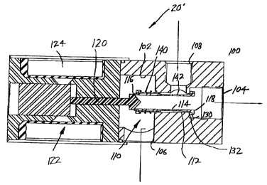
Turning now to Figure 3, a greatly simplified
proportional modulator valve 20' is shown. It includes a
housing 100 having a cavity or chamber 102. A first or
delivery port 104 is in selective communication with a
single, second or exhaust port 106 and a third or supply
port 108. A valve assembly 110 includes a hollow
cylindrical spool valve 112 having a passage 114 that
extends from a first end 116 to a second end 118. For
purposes of comparison, the passage 114 has a diameter of
0.378 inches - approximately four times the diameter of
the spool passage of the prior art. The first end of the
CA 02285774 1999-10-08
_ 7 _
spool valve defines a valve seat for piston 120 of
solenoid actuator 122.
As described in conjunction with the prior art
arrangement of Figure 2, the solenoid actuator includes
a
coil 124 that receives a signal from an electronic control
unit. Thus when the coil is energized, the piston 120 is
urged rightwardly into engagement with the first end 116
of the spool valve. Until that time, the piston is spaced
from the first end of the spool valve so that the delivery
and exhaust ports i04, 106 are in direct communication.
through the enlarged diameter passage 114 of the spool
valve. Movement of the spool valve rightwardly from the
position shown in Figure 3 allows the seal 130 to move
from its valve seat 132 defined in the housing. This
establishes communication between the supply pressure port
108 and the delivery port 104. When the supply port is
connected to the delivery port, pressurized air also
passes through the central opening 114 and against the
face of the piston that engages the first end of the spool
2o valve. This pressure urges the piston leftwardly against
the energization force of the armature so that a
proportioned amount of pressurized air reaches the
delivery port.
A biasing member such as spring 140 is
interposed between the housing and the first end of the
spool valve. As shown, the spring is disposed along an
external surface of the spool valve at a region leftwardly
of the reduced diameter region 142 that defines the supply
pressure passage when the spool valve is moved off of the
seat 132. The enlarged diameter passage 114 through the
spool valve provides not only a direct exhaust, but a
quick exhaust for communication between ports 104, 106.
As will be appreciated, the opening has a diameter just
less than the seat area 116 defined at the first end of
the spool member. This arrangement allows a number of
components to be eliminated from the current design shown
in Figure 2. For example, the diaphragm and quick exhaust
CA 02285774 1999-10-08
_ g
port 62 of Figure 2 are entirely eliminated. Moreover,
the spool valve is a simpler structure and the stationary
sleeve used in the current design in which the spool valve
reciprocates is also eliminated.
Most importantly, a major distinction is the
relative sizes of the openings through the spool valves.
As will be appreciated, it is this diameter that controls
the quick exhaust function since the spool valve passage
provides an open communication path between the delivery
and exhaust ports. The small diameter exhaust port 54 in
the arrangement of Figure 2 is also eliminated. Instead,
a single exhaust port 106 is provided in the embodiment of
Figure 3. This allows the exhaust port 106 to be sized so
as not to restrict the exhaust function and thus provides
a quick acting response when braking action is released
and the delivery and exhaust ports are in open
communication upon retraction of the piston.
In addition, the design of Figure 3 still
provides a quick exhaust. By quick exhaust is meant the
time in which pressure decreases, for example, from 95 psi
to 5 psi. Measured test results are graphically
illustrated in Figure 4 and exhibit a quick exhaust on the
order of 0.23 seconds for the current design. The
simplified design of Figure 3 meets or exceeds the exhaust
time of the current design at a measured quick exhaust
time of 0.186 seconds.
The invention has been described with reference
to the preferred embodiment. It is understood, however,
that a number of other changes could be made to the
preferred arrangement without departing from the scope and
intent of the subject invention. For example, alternative
electrical actuators could be used instead of the solenoid
actuator. Likewise, alternative seal arrangements could
be used such as a ball seal or elastomeric poppet as
opposed to the O-ring type designs. However, such
adaptations and variations of the valve would be apparent
CA 02285774 1999-10-08
_ g _
to one skilled in the art and still fall within the scope
of the invention as defined in the accompanying claims.