Note: Descriptions are shown in the official language in which they were submitted.
02285986 19b013
99--. , . 1-
IlVIPSTENT CONFIGURATYONS
BACKGROUND OF THE IlWE'NTION
1. ield of the Invention
This invcmion relates to stents of improved configuration which
incorporate coiled articulatioDs whieh unwind to form bracing structures or
scaffolding upon expansion.
rief I2escrinis9f e Pri r Art
Stents are radially expandable endoprosthcsis which are typicaUy
intravascular itnplants capable of being implanted transluminally and enlarged
radially
afier being introduced percutaneously. They have also been implanted in
urinary
tracts and bile ducts. They are used to reinforce body vessels and to prevent
restenosis following angioplasty in the vascular svstem. They may be self-
expanding
or expanded by an internal radial force, suich as when mounted on a balloon.
An example of a stent is shown in EP 0 421729 which discloses a stent
with segments connected together by coiJed hinges.
In the past, stents have assumed many conflgura.tions and been made of
many rnatcrials, including metals and plastic. Ordinary metals such as
stainless steel
have been used as have shape memory metals such as nitinol and the like.
Stents have
also been made of biodegradable plastic materials. They have been formed from
wire,
tube stock, etc.
SLTNLMAtY OF THE INVBIYTION
This invention provides a new configuxation for stents which may be
adapted by all of the various types of prior art stents referred to
hereinabove. There
are numerous advantages to the new conftguradon. It limits recoil and adds
resistance
to compression for the expanded stent, among other things. It is
longitudinally
flexkle in both the unexpanded and ezpanded conditions. It has several
embodiments.
An importaut part of the new configuration includes a coil or coil-like
structure comprised of joined clements which are coiled or bent and which
unwind,
uncoil or unbend to a more or less straightened condition on expansion of the
stent.
Such structnres are hereinafte,r referttd to collectively as coils, spirals or
coil-like
structures. These structures provide regions of low strain in tfie sbem during
A~.fFA't>~fl S#1EfT
CA 02285986 1999-10-13
WO 98/48733 PCT/US98/08275
-2-
expansion.
These elements may be joined to each other or to any radially expansive
members of any kind, annular serpentine members being preferred.
Brief Description of the Fi res
Figure 1 is a flat view of one pattern embodiment of a stent
configuration of the invention (unexpanded);
Figure 2 is a detail of a portion of Figure 1;
Figure 3 is an end view of a stent of the Figure 1 pattern according to
the invention showing it in tubular configuration;
Figure 4 is a showing of a stent in the embodiment of the preceding
Figures in perspective and in an unexpanded configuration;
Figure 5 is a showing of the stent of Figure 4 fully expanded with
details of the front and rear of the stent;
Figures 6, 7 and 8 are showings of the stent of Figure 4 in various
stages of expansion with only details of the front of the stent shown for
simplicity;
Figure 9 is a plan view showing another embodiment of the invention;
Figure 10 is a showing of a modified embodiment;
Figure 11 is a showing of another embodiment;
Figure 12 is a detail of a portion of Figure 11;
Figure 13 is a showing of the stent of Figures 11 and 12 in an expanded
configuration;
Figure 14 is a showing of another embodiment;
Figure 15 is a showing of still another embodiment;
Figure 16 is a showing of yet another embodiment;
Figure 17 is a showing of still another embodiment;
Figures 18-28 show various coil-like arrangements of the invention;
Figure 29 shows another embodiment of the invention;
Figure 30 shows yet another embodiment; and
Figure 31 shows still another embodiment of the invention.
CA 02285986 1999-10-13
WO 98/48733 PCTIUS98/08275
-3-
DETAILED DESCRIPTION OF THE PREFERRED EMBODIMENTS
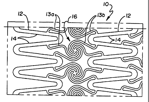
One preferred embodiment of the invention is illustrated in Figures 1-8.
It comprises a metal tube-like structure 10 as best shown in Figures 3 and 4,
such as
nitinol or stainless steel, which has been etched or laser cut to the
configuration shown
in the plan view of Figures 1 and 2 and in a short version as shown in Figure
4. The
configuration is made up of a series of serpentine annular expandable elements
or
segments 12 which form loops 14 to allow for radial annular expansion.
Segments 12
may be other configurations but serpentine is preferred. Elements 12 are
interconnected by pairs of elongated members 13a and 13b which are attached at
one
end to successive loops 14 of a segment 12 and which are joined at their other
ends to
adjacent pairs of elongated members 13a and 13b, as best seen in detail in
Figure 2.
Members 13a and 13b are preferably of narrower gauge than members 12 and are
joined together in a coiled or spiral arrangement as shown generally at 16.
Spiral 16
forms a structure about which members 13 may uncoil or unwind in a
counterclockwise direction or clockwise direction to a substantially straight
condition,
depending on the spiral winding direction, upon radial expansion of members
12. In
this embodiment spirals 16 are formed in alternate wound structures so that
some
unwind in one direction and some in the other direction. Of course, in any
embodiment the spirals can be formed so that they all unwind in one direction,
either
clockwise or counterclockwise and they may have more or fewer members 13.
Also,
more or less spirals may be included between the segments. The uncoiling is
accompanied by a straightening action with respect to members 13 as is
described in
more detail in connection with Figures 4-8. It can be seen from Figures 4
through 8
that the resultant configuration in an expanded stent of this configuration is
comprised
of a plurality of cells, the perimeter of each of which is defmed by a pair of
members
or struts defined by the loop portion 14 of segment 12 and a pair of members
or struts
13. The cells are joined at 16 as best seen in Figure 8. More specifically the
cells are
of two kinds as shown in Figure 8. A first pair of cells are A and B made up
of a
segment 12 and two struts 13a for cell A or 13b for cell B. A second pair of
cells are
C and D made up of an inward loop portion 14 of segment 12 and a strut 13a and
a
strut 13b for cells C and D.
CA 02285986 1999-10-13
WO 98/48733 PCT/US98/08275
-4-
When a stent of the invention, such as that shown in Figures 1-4
undergoes expansion, such as from the embodiment of Figure 4, it will appear
as
shown in Figure 5 in the fully expanded condition. Figure 5 shows the stent in
perspective.
The unwinding action which the coil elements 16 undergo upon stent
expansion is best seen in Figures 6-8 which show only the front side surface
of the
stent for simplicity and clarity.
As radial expansion begins (seen in Figure 6) it can be appreciated that
the coil elements 16 undergo an unwinding or straightening action by a pulling
force
on all of the members 13. Specifically, as expansion occurs, elements 13
undergo a
straightening action as can be seen in the early stages of expansion in Figure
6.
Upon further expansion (seen in Figure 7), spirals 16 undergo further
unwinding, i.e., elements 13 undergo further straightening.
Finally in Figure 8, substantial full expansion provides substantially 15
straightened elements 13 which in that condition limit stent recoil and
increase the
resistance to compression of the stent.
Figure 9 shows a modified embodiment in which elements 13a and 13b
contact segment 12 at the end of its loops 14. Also note in this embodiment
that the
coils 16 are all wound in the same direction.
Figure 10 shows an embodiment of the invention in which the spiral
members 13 are more bent and less curvilinear but still form a coil-like
configuration
16. The remainder of the configuration is similar to that of Figure 9. In
Figure 10,
elongate members 13 are shown prior to expansion of the stent. When the stent
is
expanded, members 13 unwind counter-clockwise and straighten somewhat. At full
expansion members 13 straighten still further and straighten substantially so
as to
provide resistance to compression of the stent and low recoil. The expanded
configuration displays a cell configuration similar to that seen in Figure 8.
Other embodiments are shown in subsequent Figures with different coil
arrangements. For example, the embodiment of Figures 11-13 shows coiled
arrangements 16 which are wound in the same direction and elements 13 attached
at
the end of loops 14 while some adjacent coils between segments are
interconnected by
members 15.
CA 02285986 1999-10-13
WO 98/48733 PCT/US98/08275
-5- =
Figure 14 shows some elements 13 in a spiral 16 contacting the end of
loops 14 and some contacting segment 12 proper. Also, some adjacent coils are
interconnected by members 17.
Figure 15 shows a flattened or elongated coil arrangement 16 and
elements 12 are angled with respect to the longitudinal axis of the stent. In
previous
embodiments, these elements or segments have been arranged parallel to the
axis or
horizontal. Elongated spirals as in Figure 13 and coils of previous Figures
may be
mixed together. (Not shown).
In the embodiments already discussed, annular expandable segments
such as segments 12 are interspersed with coil arrangements 16. However, as
can be
seen in Figure 16, at least a substantial portion or all of the stent body can
be merely
comprised of spiral arrangements 16 connected to each other. Actually, all of
the
body may consist of spirals. In this embodiment, the elements 13 interconnect
between spirals over substantially the entire body of the stent. Optionally,
the ends-
may include segments 12 as shown.
The embodiment shown in Figure 17 shows segments 12 alternately
angled in opposite directions and with legs thereof of different length and
elements 13
contacting the segments at different locations, i.e., as at the loop portion
14 and at the
segment portion proper.
Figures 18-28 demonstrate examples of what is meant by the terms coil,
spiral and coil-like herein. Of course, additional members may be included in
the
coils.
Figure 29 shows segments 12 in a configuration other than the annular
serpentine configuration of previous Figures.
Figure 30 shows alternate segments 12 in serpentine annular
configuration interconnected by double rows of interconnected coil
configurations 16.
Figure 31 is included to demonstrate that coils 16 may be included on
the ends of a stent 10.
= While this invention may be embodied in many different forms, there
are described in detail herein specific preferred embodiments of the
invention. This
description is an exemplification of the principles of the invention and is
not intended
to limit the invention to the particular embodiments illustrated.
CA 02285986 1999-10-13
WO 98/48733 PCT/US98/08275
-6-
The above Examples and disclosure are intended to be illustrative and
not exhaustive. These examples and description will suggest many variations
and
alternatives to one of ordinary skill in this art. All these alternatives and
variations
are intended to be included within the scope of the attached claims. Those
familiar
with the art may recognize other equivalents to the specific embodiments
described
herein which equivalents are also intended to be encompassed by the claims
attached
hereto.
F:\WPWORK\OFA\6336-APP.214