Note: Descriptions are shown in the official language in which they were submitted.
CA 02286027 1999-10-OS
DESCRIPTION
COIN SORTER
TECI~ICAL FIELD
The present invention relates to a coin sorter which sorts inserted coins
into authentic or counterfeit and coins sorted as authentic by denomination,
and more particularly to a configuration for fitting independent components of
the coin sorter.
BACKGROUND ART
Generally speaking, coin sorters identify each of inserted coins as
authentic or counterfeit, further identify the denominations of coins
identified
as authentic, and sort these inserted coins by channelling each of these coins
into different coin passages.
Such coin sorters consist of various independent components such as a
main plate which constitutes the body of the device, and a front cover which
covers the front surface of the main plate in such a manner that it is capable
of
being opened and closed freely.
The main plate, being one of these independent components, is
equipped with a coin inlet through which the coins are inserted, and
electronic
coin identifying means which is referred to as a coin sensor and identifies
inserted coins as authentic or counterfeit and the denominations of authentic
coins. A coin sorting lever located on the main plate is operated in
accordance
with signals transmitted by the electronic coin identifying means, which
indicate that inserted coins are authentic or counterfeit and further indicate
the
denominations of authentic coins, so that the inserted coins are each
1
CA 02286027 1999-10-OS
channelled into different coin passages, thus sorting them into authentic or
counterfeit and further sorting authentic coins by denomination.
As mentioned above, the main plate also has other independent
components such as coin passages which serve to guide the coins by
denomination and a sorting lever. These components are normally covered
with the front cover so as not to be exposed. At the front cover, a portion of
the coin passages may be formed on the rear side thereof.
One of the functions of this front cover is to allow the front of the main
plate to be opened up to reveal the coin passages, sorting lever and other
components disposed on the front cover during servicing and maintenance of
these components, with the object of facilitating the operation of servicing
and
maintenance. The front cover of a conventional type is an independent
component, and is configured in such a manner that it is fitted on to the main
plate by engaging claws formed on either side of it with apertures formed on
either side of the main plate.
The abovementioned coin sorter is equipped also with a metal gate rail
serving directly to receive coins which drop down from the coin inlet, and
guide them towards the coin passage in which is located the electronic coin
identifying means referred to as a coin sensor, which serves to identify coins
received in this manner as authentic or counterfeit, and further identify the
denominations of authentic coins. Coins passing along the coin passage in
which the electronic coin identifying means is located are identified during
their passage by the electronic coin identifying means as authentic or
counterfeit, and authentic coins are further identified by denomination.
Inserted coins passing through the abovementioned coin passage are
further guided into a plurality of coin passages which branch off from the
abovementioned coin passage. At each of the points where the plurality of
2
CA 02286027 1999-10-OS
coin passages branch off is located a coin sorting lever, being another
independent component, which is operated in accordance with coin
identification signals transmitted from the electronic coin identifying means,
and serves to channel the inserted coins into each of the plurality of the
branch
coin passages, thus sorting coins as authentic or counterfeit and further
sorting
authentic coins by denomination.
The coin sorting lever is an independent component and is driven by a
solenoid which operates in accordance with coin identification signals
transmitted from the electronic coin identifying means.
The gate rail, which is another independent component of the coin
sorter, and the solenoid which drives the coin sorting levers have
conventionally been configured in such a manner that screws are used to
attach them in prescribed positions on the coin sorter.
In other words, the gate rail, which is an independent component, is
attached by means of screws on to the gate plate which serves to open and
close the coin inlet. Meanwhile, the solenoid, which drives the coin sorting
levers, is attached by means of screws to the rear surface of the main plate
which constitutes the body of the coin sorter.
Now, inasmuch as the conventional coin sorter is configured in such a
manner that the front cover is attached by engaging claws formed on either
side of it with apertures formed on either side of the main plate, it presents
problems because the operation of attaching it is extremely troublesome. Not
only that, but when the front cover is to be removed from the main plate
during maintenance and servicing, it is necessary to disengage the engaging
claws from the apertures, and this also is a troublesome operation.
Moreover, inasmuch as the conventional coin sorter is configured in
such a manner that the gate rail and solenoid, which are independent
3
CA 02286027 1999-10-OS
components thereof, are attached in prescribed positions on the coin sorter
with the aid of screws, the operation of attaching and detaching them is
complicated, so that the number of processes required for assembling the
device is increased, and the number of operations which need to be performed
during maintenance and servicing thereof is also increased. This in turn makes
the device more costly, and increases the expenditure involved in maintenance
and servicing.
In a view of the abovementioned circumstances, it is an object of the
present invention to provide a coin sorter which is easy to attach and detach
independent components thereof to and from it.
DISCLOSURE OF THE INVENTION
With the aim of solving the abovementioned problems, the first coin
sorter to which the present invention pertains is a coin sorter comprising a
main plate which constitutes a body of the device, and a front cover which
covers a front surface of the main plate in such a manner as to be capable of
being opened and closed freely, characterized in that the coin sorter further
comprises a shaft provided on one edge of the front cover; and bearing means
provided on one edge of the main plate in such a manner that the shaft is
fitted
into the bearing means from one direction by virtue of a snap action and
rotatably supported by the bearing means, whereby the front surface of the
main plate is covered with the front cover in such a manner as to be capable
of
being opened and closed freely by rotating the front cover about the shaft.
With the configuration in which a shaft formed on one edge of the front
cover is inserted by virtue of a snap action into bearing means formed on one
edge of the main cover, and is supported by it in such a manner that the front
cover is capable of being rotated freely around the shaft means, the front
cover
4
CA 02286027 1999-10-OS
can be attached and detached in a simple operation, thus reducing the number
of manufacturing processes involved especially in the operation of assembling
the coin sorter, and considerably improving ease of assembly, while at the
same time greatly facilitating the operation of maintaining and servicing the
device.
The second coin sorter to which the present invention pertains is a coin
sorter characterized in that a snap-type gate rail supporting means is
provided
below a coin inlet, whereby a gate rail which directly receives coins falling
down from the coin inlet and guides the coins towards a prescribed coin
passage is fitted into and supported by the gate rail supporting means by
virtue
of a snap action.
Further, the third coin sorter to which the present invention pertains is a
coin sorter characterized in that the main plate which constitutes a body of
the
device is formed with a snap-type solenoid supporting means, whereby a
solenoid for driving a coin sorting lever which serves to channel inserted
coins
towards different coin passages is fitted into and supported by the solenoid
supporting means by virtue of a snap action.
With the configuration of the second and third coin sorters to which the
present invention pertains, the independent components which constitute the
device, and especially the gate rail and the solenoids which drive the coin
sorting levers, are supported by virtue of a snap action in prescribed
positions
on the coin sorter in such a manner as to be capable of being attached and
detached freely means that the gate rail and solenoids can be attached and
detached in a simple operation, reducing the number of manufacturing
processes involved especially in the operation of assembling the coin sorter,
and considerably improving ease of assembly, while at the same time greatly
facilitating and accelerating the operation of maintaining and servicing the
5
CA 02286027 1999-10-OS
device. In this way it is possible to reduce the costs both of manufacturing
the
coin sorter, and of maintaining and servicing it.
BRIEF DESCRIPTION OF THE DRAWINGS
Fig. 1 is a front view of the first coin sorter to which the present
invention pertains;
Fig. 2 is an exploded perspective view of principal portions of the first
coin sorter to which the present invention pertains;
Fig. 3 is a perspective view of principal portions of the first coin sorter
to which the present invention pertains;
Fig. 4 is an exploded perspective view of the latching means;
Fig. 5 is a perspective view of the latching means;
Fig. 6 is a side view illustrating the action of the first coin sorter to
which the present invention pertains;
Fig. 7 is a side view illustrating the action of the first coin sorter to
which the present invention pertains;
Fig. 8 is a sectional view of the principal part of the coin sorter viewed
along the line E-E in Fig. 7;
Fig. 9 is a view showing the front cover closed in Fig. 8;
Fig. 10 is a sectional view of the principal part of the coin sorter viewed
along the line F-F in Fig. 7;
Fig. 11 is a front view of the second and third coin sorters to which the
present invention pertains;
Fig. 12 is an exploded perspective view of principal portions of the
second and third coin sorters to which the present invention pertains;
Fig. 13 is a perspective view of principal portions of the second and
third coin sorters to which the present invention pertains;
6
CA 02286027 1999-10-OS
Fig. 14 is a sectional view of the principal part viewed along the line B-
B in Fig. 13;
- Fig. 15 is a partially cut-away rear view of principal portions of the
second and third coin sorters to which the present invention pertains;
Fig. 16 is an exploded perspective view of principal portions of the
second and third coin sorters to which the present invention pertains; and
Fig. 17 is a perspective view of principal portions of the second and
third coin sorters to which the present invention pertains.
BEST MODE FOR CARRYING OUT THE INVENTION
There follows a detailed description of a first embodiment of the coin
sorter to which the present invention pertains.
Fig. 1 is a front view of the first coin sorter to which the present
invention pertains.
This coin sorter 1 is a compact model of the sort which may especially
be installed between pin-ball and other gaming machines. It handles only a
relatively small number of denominations of coin, identifying and sorting two
types of coin of differing diameters, and identifying any other coins as
counterfeit.
The coin sorter 1 comprises a main plate 3, on the upper surface of
which is formed a coin inlet 2. The upper front surface of the main plate 3 is
covered with a gate plate 4, which can be opened and closed freely, while the
lower front surface is covered with a front cover 5.
In the part of the main plate 3 which is covered with the gate plate 4 is
formed a coin passage, which is not illustrated in the drawing but which
serves
to guide coins inserted through the coin inlet 2. This coin passage is
equipped
with an electronic coin identifying means, which serves to identify inserted
7
CA 02286027 1999-10-OS
coins as authentic or counterfeit, and further to identify the denominations
of
authentic coins. Meanwhile, in the part of the main plate 3 which is covered
with the front cover 5 are formed coin sorting levers, which are not
illustrated
in the drawing but which serve to sort the inserted coins, and different coin
channels which guide the coins sorted by means of these coin sorting levers
according to their denomination.
On the right-hand side Sa of the front cover 5 protrudes integrally a
shaft 6, while on the right-hand side 3a of the main plate 3 facing this shaft
6
is formed integrally bearing means 7 into which by virtue of a snap action the
shaft is inserted from one direction and thus supported.
Meanwhile, on the left-hand side Sb of the front cover 5 and on the left-
hand side 3b of the main plate 3 facing it are formed latching means 10 which
similarly by virtue of a snap action serve to support the left-hand side Sb of
the
front cover 5 on the main plate 3.
There follows a detailed description of the abovementioned shaft 6
formed on the front cover 5, and the bearing means 7 formed on the main plate
3.
Fig. 2 is an exploded perspective view of principal portions of the first
coin sorter to which the present invention pertains, and illustrates the shaft
6
and the bearing means 7 into which the shaft 6 is inserted and thus supported.
More precisely, it depicts the front cover 5 detached from the main plate 3
and
allowed to stand upright in relation to the main plate 3.
The shaft 6 is formed on the leading edge of a tongue Sc, which has a
roughly L-shaped cross section and extends from the right-hand side Sb of the
front cover 5. One centrally located portion of the peripheral surface 6a
thereof is provided with an engagement member 6b which protrudes towards
the main plate 3.
8
CA 02286027 1999-10-OS
Meanwhile, the bearing means 7 comprises three tongues 20, 21, 22
located on the right-hand side 3a of the main plate 3, and a pair of bearing
- members 23, 24 formed in positions on either side of these three tongues 20,
21, 22. It should be added that this pair of bearing members 23, 24 and the
three tongues 20, 21, 22 are formed integrally with the main plate 3.
On the upper surfaces of the pair of bearing members 23, 24 are formed
depressions 23a, 24a having half moon-shaped cross section into which are
inserted the corresponding ends 6c, 6d of the shaft 6 in such a manner as to
be
supported. Arc-shaped portions 20a, 22a are formed parallel to the peripheral
surface 6a of the shaft 6 on the sides of each of the three tongues 20, 21, 22
with the exception of the tongue 21 which is located in the center, the
purpose
being to support part of the peripheral surface 6a of the shaft 6.
In addition, inclined surfaces 20b, 22b are formed on the upper portions
of the tongues 20, 22 so that when the shaft 6 is inserted and supported on
them, they come into contact with the peripheral surface 6a thereof, causing
the tongues 20, 22 to deflect with a snap action in a clockwise direction
around their bases.
On the centrally located tongue 21 is formed an engagement aperture
21 a with which the aforesaid engagement member 6b provided on the
peripheral surface 6a of the shaft 6 engages when the shaft 6 is rotated to a
prescribed angle, and which serves to restrict rotation beyond this prescribed
angle. Additionally, there is located on the main plate 3 in a position facing
this engagement aperture 21a an engagement member 3c, which similarly
serves to restrict rotation of the shaft 6 beyond this prescribed angle.
As may be seen from Fig. 2, the action of the shaft 6 and the bearing
means 7 formed on the front cover 5 and main plate 3 respectively is as
follows. If the front cover 5 is caused to move vertically downwards as
9
CA 02286027 1999-10-OS
represented by the arrow A while still standing upright in relation to the
main
plate 3, what happens first is that the peripheral surface 6a of the shaft 6
comes into contact with the inclined surfaces 20b, 22b of the tongues 20, 22,
thus causing the tongues 20, 22 to deflect with a snap action in a clockwise
direction around their bases. It continues to move downwards, and as Fig. 3
demonstrates, the ends 6c, 6d of the shaft 6 fit into the depressions 23a, 24a
of
the bearing members 23, 24. At the same time, the tongues 20, 22 shown in
Fig. 2 spring back to their initial position, so that the peripheral surface
6a of
the shaft 6 is supported by the arc-shaped portions 20a, 22a of the tongues
20,
22, while being held within the depressions 23a, 24a.
In other words, lowering the abovementioned front cover 5 from a
upright position (from one direction) in relation to the main plate 3 allows
the
shaft 6 to be inserted by virtue of the snap action of the pair of tongues 20,
22
into the depressions 23a, 24a of the pair of bearing members 23, 24 and to be
supported there, further allowing the front cover 5 to be supported in such a
manner as to be capable of rotating freely around the shaft 6.
Meanwhile, as Fig. 3 shows, if the front cover 5 is caused to move
vertically upwards as represented by the arrow B while still standing upright
in relation to the main plate 3, what happens is that the tongues 20, 22,
which
engage with the peripheral surface 6a of the shaft 6 through the medium of the
arc-shaped portions 20a, 22a depicted in Fig. 2, deflect from their initial
position in a clockwise direction around their bases. As a result of this, the
peripheral surface 6a of the shaft 6 is released from the support of the arc-
shaped portions 20a, 22a of the tongues 20,22, allowing the front cover 5 to
be
detached easily from the main plate 3.
As will be clear from Fig. 3, any attempt to rotate the front cover 5 in a
clockwise direction around the shaft 6 from an upright position in relation to
CA 02286027 1999-10-OS
the main plate 3 results in contact between the engagement member 6b located
on one portion of the peripheral surface ba and the engagement member 3c
formed on the main plate 3, thus restricting rotation of the front cover 5 in
a
clockwise direction.
If an attempt is made from the state illustrated in Fig. 3 to rotate the
front cover 5 slightly around the shaft 6 and then release the front cover 5,
both the interior peripheral surfaces of the depressions 23a, 24a in the
bearing
members 23, 24 and the arc-shaped portions 20a, 22a engage with the shaft 6,
preventing it from being released and making it impossible to attach or detach
the front cover 5 from that direction.
Consequently, attachment and detachment of the front cover 5 can be
effected only in one direction where the front plate 5 is upright in relation
to
the main plate 3, as illustrated in Fig. 2.
Meanwhile, as the enlarged disassembled perspective view depicted in
Fig. 4 shows, the latching means 10 which serves to support the left-hand side
Sb of the front cover 5 on the left-hand side 3b of the main plate 3 as
illustrated in Fig. 1 comprises a pair of arms 30, 31 which extend towards the
left-hand side 5b of the front cover 5 in such a manner as to be capable of
being deflected in a horizontal direction by virtue of a snap action, engaging
claws 30a, 31a which are formed on the leading edges of the arms 30, 31 and
have a roughly L-shaped cross section, and a pair of engaging claws 40, 41
which are formed on the main plate 3 in positions facing the engaging claws
30a, 31a of the arms 30, 31.
On the lower surfaces of the pair of engaging claws 30a, 31a and on the
upper surfaces of each of the pair of engaging claws 40, 41 are formed
inclined surfaces 30b, 31b, 40a, 41a which by coming into contact with each
other serve to deflect the pair of arms 30, 31 in a direction of making closer
to
11
CA 02286027 1999-10-OS
each other.
As is demonstrated by the arrows C in Fig. 4, when the front cover 5 is
pressed towards the main plate 3 and the inclined surfaces 30b, 31b of the
pair
of engaging claws 30a, 31a are allowed to slide into contact against the
inclined surfaces 40a, 41a of the pair of engaging claws 40, 41, the
abovementioned latching means 10 causes the pair of arms 30, 31 to deflect
towards each other, thus decreasing the distance between them.
If the front cover 5 is pressed further against the main plate 3 so as to
release the contact between the inclined surfaces 30b, 31b of the pair of
engaging claws 30a, 31 a and the inclined surfaces 40a, 41 a of the pair of
engaging claws 40, 41, the deflected pair of arms 30, 31 return to their
initial
positions by virtue of a snap action. Thus, as Fig. 5 shows, the pair of
engaging claws 30a, 31a on the front cover 5 and the pair of engaging claws
40, 41 on the main plate 3 engage with each other, which serves to allow the
left-hand side Sb of the front cover S to be supported on the left-hand side
3b
of the main plate 3.
In other words, the pair of engaging claws 30a, 31a on the front cover 5
engage with the pair of engaging claws 40, 41 by virtue of the snap action of
the pair of arms 30, 31.
It should be added that the abovementioned pairs of engaging claws 30a,
31 a and 40, 41 can easily be released from each other if the operator grasps
the pair of arms 30, 31 and causes them to deflect towards each other as
illustrated by the arrows D in Fig. 5.
There follows a detailed description of the operation of attaching and
detaching the front cover 5.
First of all, in order to attach the front cover 5 to the main plate 3, the
front cover 5 is made to stand upright in relation to the main plate 3 of the
coin
12
CA 02286027 1999-10-OS
sorter l, which is placed horizontally as depicted in Fig. 6, where the same
parts are allocated the same numerals or symbols as in Figs. 1-3. The front
cover 5 is then lowered as represented by the arrow A, thereby causing the
shaft 6 formed on the front cover 5 to be inserted into the bearing means 7 on
the main plate 3 in such a manner as to be supported there. Thus, by virtue of
the snap action the front cover 5 is easily attached to the main plate 3.
Meanwhile, when the shaft 6 of the front cover 5 has been inserted into
the bearing means 7 of the main plate 3 and is supported by it as in Fig. 7,
the
engagement member 6b located on the peripheral surface of the shaft 6 and the
engagement member 3c formed on the main plate 3 are positioned so as to
come into contact with each other, as may be seen from Fig. 8, which is a
sectional view of the principal part along the line E-E in Fig. 7. As a
result,
rotation of the front cover 5 in a clockwise direction around the shaft 6 from
the initial position depicted in Fig. 8 is restricted, and only rotation in an
anticlockwise direction is permitted. This means that it is impossible to open
the front cover 5 further than necessary in a clockwise direction around the
shaft 6.
If the front cover is rotated in an anticlockwise direction around the
shaft 6 from the position illustrated in Fig. 8, and the main plate 3 is
closed,
the engagement member 6b located on the peripheral surface of the shaft 6
comes into contact with the engagement aperture 21a formed in the tongue 21,
with the result that excessive rotation of the front cover 5 in an
anticlockwise
direction around the shaft 6 is also restricted.
The left-hand side of the front cover 5 is attached by virtue of a snap
action to the left-hand side of the main plate 3 by means of the latching
means
10 illustrated in Figs. 4 and 5.
It should be added that when the shaft 6 of the front cover 5 has been
13
CA 02286027 1999-10-OS
inserted into the bearing means 7 of the main plate 3 and is supported by it
as
in Fig. 7, the peripheral surface 6a of the shaft 6 is supported by the arc-
shaped portions 20a, 22a of the tongues 20, 22, so as to prevent the shaft
from
becoming detached from within the depressions 23a, 24a (Fig. 2) as shown in
Fig 10 which is a sectional view of the principal part of the coin sorter
viewed
along the line F-F in Fig. 7.
In the above embodiment, the invention to which the present application
pertains has been described in detail as applied to a compact model of the
sort
which may especially be installed between pin-ball and other gaming
machines, and which handles only a relatively small number of denominations
of coin, identifying and sorting two types of coin of differing diameters, and
regarding any other coins as counterfeit. However, in addition to the above
embodiment, the present invention may also be applied to a larger coin sorter
for sorting a large number of denominations such as may be installed inside
automatic vending machines and similar apparatus.
There follows a detailed description of an embodiment of a second and
third coin sorters to which the present invention pertains.
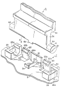
Fig. 11 is a front view of the second and third coin sorters to which the
present invention pertains.
This coin sorter 51 is also a compact model of the sort which may
especially be installed between pin-ball and other gaming machines. It handles
only a relatively small number of denominations of coin, identifying and
sorting two types of coin of differing diameters and regarding any other coins
as counterfeit.
This coin sorter 51 comprises a main plate 53 on the upper surface of
which is formed a coin inlet 52. The upper front surface thereof is covered
with a gate plate 54, which can be opened and closed freely, while the lower
14
CA 02286027 1999-10-OS
front surface is covered with a front cover 55.
Between this gate plate 54 and the main plate 53 is formed a coin
passage 57, which serves to guide coins 56 inserted through the coin inlet 52.
This coin passage 57 is equipped with an electronic coin identifying means 58,
which serves to identify inserted coins as authentic or counterfeit, and
further
to identify the denominations of authentic coins.
Moreover, in the part of the main plate 53 which is covered with the
front cover 55 are formed coin sorting levers, which will be described later
and which serve to sort the inserted coins, and a plurality of coin channels
which guide the coins sorted by means of these coin sorting levers according
to their denomination.
Meanwhile, on the abovementioned gate plate 54 in a position below
the coin inlet 52 is formed snap-type gate rail supporting means 70, into
which
by virtue of a snap action the gate rail 60 is inserted and thus supported,
the
gate rail 60 serving directly to stop coins 5b which drop down from the coin
inlet 52, and guide them towards the coin passage 57.
There follows a detailed description of the abovementioned gate rail 60
and the snap-type gate rail supporting means 70.
Fig. 12 is an exploded perspective view of principal portions of the gate
plate 54.
In Fig. 12, the gate rail 60 is formed with a metal plate 61, behind which
extend on either side engagement members 62, 63, with a concave portion 64
formed between them.
Meanwhile, the snap-type gate rail supporting means 70 comprises an
aperture 71 into which is inserted the forward portion 60a of the gate rail
60,
and an engaging claw 72 which is elastic and freely deformed and which
supports the trailing edge 60b of the gate rail 60 inserted into the aperture
71.
__.a_... _ _~_ . _ .___
r _.
CA 02286027 1999-10-OS
The base 72a of this engaging claw 72 is fixed to the gate plate 54,
while the free end 72b thereof extends towards the top of the aperture 71,
there
being formed between these a curved portion 72 roughly in the shape of an arc,
by virtue of which the engaging claw 72 is rendered elastic and capable of
being deformed both backwards or forwards and upwards or downwards
around the base 72a.
On the lower inner peripheral wall of the aforesaid aperture 71 are
formed integrally a pair of supporting plates 71a, 71b which serve to support
the lower surface 61a of the gate rail 60, while the upper surface 61b of the
plate 61 which constitutes the gate rail 60 is configured in such a manner
that
it is supported by the upper inner peripheral wall 71 c of the aperture 71.
With the snap-type gate rail supporting means 70, the gate rail 60 is
brought into the proximity of the hole 71 as represented by the arrow A in
Fig.
12, and the leading edge 60a thereof is inserted between the upper inner
peripheral wall 71 c of the hole 71 and the free end 72b of the engaging claw
72. By virtue of its elasticity and capacity to deform, the curved portion 72c
of
the engaging claw 72 moves downwards, allowing the space between the top
and bottom of the aperture 71 to widen and the leading edge 60a of the gate
rail 60 to be inserted. On insertion, once the concave portion 64 formed on
the
trailing edge 60b of the gate rail 60 has passed the free end 72b of the
engaging claw 72, the curved portion 72c of the engaging claw 72 returns by
virtue of its elasticity to its initial position. As a result, the free end
72b of the
engaging claw 72 engages with the concave portion 64 of the gate rail 60, as
Fig. 13 shows. In this manner the gate rail 60 is inserted into the aperture
71
and supported by virtue of a snap action.
As may be seen from Fig. 14, which is a sectional view of the principal
part along the line B-B in Fig. 13, the lower surface 61 a of the plate 61
which
16
CA 02286027 1999-10-OS
constitutes the gate rail 60 is supported by the inclined upper surfaces 71 d,
71 a
of the pair of supporting plates 71a, 71b, while the upper surface 61b of the
plate 61 is supported, as already mentioned, by the upper inner peripheral
wall
71 c of the aperture 71.
As Fig. 13 shows, the configuration in which the gate rail 60 is inserted
into the aperture 71 and supported there serves to ensure that the pair of
engagement members 62, 63 on the gate rail 60 engage with the perimeter of
the aperture 71 and prevent it from being released.
In order to release the gate rail 60 from within the aperture 71 which
constitutes the snap-type gate rail supporting means 70 illustrated in Fig.
13,
the free end 72b of the engaging claw 72 is pulled somewhat forwards and
deflected to disengage the free end 72b and the concave portion 64 of the gate
rail 60. This allows the gate rail 60 to be released easily from within the
aperture 71 which constitutes the snap-type gate rail supporting means 70.
The second and third coin sorters 51 to which the present invention
pertains, as may be seen from the rear view of principal portions thereof
depicted in Fig. 15, have formed on the main plate 53 a coin passage 53b
which connects to the aforesaid coin passage 57 (Fig. 11). Within this coin
passage 53b are located two coin sorting levers 80, 81, which serve to channel
inserted coins into each of the coin passages not illustrated in the drawing
which branch offthe coin passage 53b.
These two coin sorting levers 80, 81 are configured in such a manner as
to be driven by two solenoids 90, 91 located on the rear surface 53a of the
main plate 53. These two solenoids 90, 91 are supported by two snap-type
solenoid supporting means 100, 101, which are formed on the rear surface 53a
of the main plate 53, and into which by virtue of a snap action the solenoids
90,
91 are inserted and thus supported.
17
CA 02286027 1999-10-OS
There follows a detailed description of the abovementioned snap-type
solenoid supporting means 100, 101. Inasmuch as both these snap-type
solenoid supporting means 100, 101 are basically configured in the same
manner, the snap-type solenoid supporting means 100 which supports the
solenoid 90 will be taken as representative, and a description of the other
snap-type solenoid supporting means 101 will be omitted.
Fig. 16 is an exploded perspective view of principal portions of the
second and third coin sorters to which the present invention pertains, and
serves to illustrate the abovementioned solenoid 90 and snap-type solenoid
supporting means 100. Components which are the same as those illustrated in
Fig. 15 have been allocated the same numerals or symbols.
This solenoid 90 comprises an electromagnetic coil 91 located at its
center, and a metal casing 92 which surrounds it. In the center is supported a
plunger 94 in such a manner as to be capable of sliding freely, this plunger
94
being located within a return spring 93. On the leading edge of this plunger
94
is formed a narrower portion 94a, which by virtue of a snap action is inserted
into and supported by the leading edge 95a of an operating lever 95 having an
L-shaped cross section. On the leading edge 95a of this operating lever 95 is
formed a notch 95b having a V-shaped cross section, and the narrower portion
94a on the leading edge of the plunger 94 is supported in an aperture 95e
formed at the base of the aforesaid notch 95b, in such a manner as to be
capable of being attached and detached freely. Moreover, on the trailing edge
95c of the aforesaid operating lever 95 is formed a notch 95d, which engages
with a drive arm 80a of the coin sorting lever 80.
Meanwhile, there are located in prescribed positions on the peripheral
surface of the casing 92 which constitutes the abovementioned solenoid 90,
namely on either side 92a, 92b of the casing 92 in the embodiment, apertures
18
CA 02286027 1999-10-OS
92c, 92d which engage with tongues 106, 107 of the snap-type solenoid
supporting means 100.
There follows a detailed description of the snap-type solenoid
supporting means 100.
As illustrated in Fig. 16, there is located in a prescribed position on the
rear surface 53a of the main plate 53 a snap-type solenoid supporting means
100.
This snap-type solenoid supporting means 100 comprises positioning
blocks 102, 103, 104, 105 which serve to position the casing 92 of the
solenoid 90 in a prescribed location on the rear surface 53a of the main plate
53, and a pair of engagement tongues 106, 107 which by virtue of a snap
action are inserted into and support the casing 92 of the solenoid 90.
One of the engagement tongues 106 is located in a position
corresponding to the aforesaid aperture 92c located on one side 92a of the
casing 92 which constitutes the solenoid 90, while the other tongue 107 is
located in a position corresponding to the aforesaid aperture 92d which is
located on the other side 92b of the casing 92.
One of the engagement tongues 106 has overall roughly the shape of an
letter M, and comprises a first tongue 106a and a second tongue 106b with a
prescribed distance between them, and a third tongue 106d which extends
downwards from roughly the center of a bridge 106c connecting the tops
thereof. On the lower edge of this third tongue 106d is located a protrusion
106e which is inserted into the aperture 92c located on one side 92a of the
casing 92 which constitutes the solenoid 90.
The other engagement tongue 107 has overall roughly the shape of a
letter U, and comprises a first tongue 107a which faces upwards, and a second
tongue 107b which extends downwards from the upper edge of the first tongue
19
CA 02286027 1999-10-OS
107a. On the lower edge of this second tongue 107b is located a protrusion
107c which is inserted into the aperture 92d located on the other side 92b of
the casing 92 which constitutes the solenoid 90.
It should be added that on the tops of each of these engagement tongues
106, 107 and positioning blocks 102, 103 are formed inclined surfaces 110 in
order to facilitate insertion of the casing 92.
Moreover, the reference numeral 80a in Fig. 16 represents a drive arm
which allows the coin sorting lever 80 to rotate around a shaft 80b.
With the abovementioned snap-type solenoid supporting means 100,
lowering the casing 92 of the solenoid 90 along with the operating lever 95 as
represented by the arrow C in Fig. 16 allows the casing 92 of the solenoid 90
to be positioned with the aid of the positioning blocks 102, 103, 104, 105 as
is
shown in Fig. 17, and the protrusions 106e, 107c located on the pair of
engagement tongues 106, 107 are inserted into the corresponding apertures
92c, 92d by virtue of a snap action. At the same time, the notch 95d in the
operating lever 95 engages with the drive arm 80a of the coin sorting lever
80.
With the configuration in which the pair of engagement tongues 106,
107 are elastic and deform in an outward direction around their bases (on the
main plate 53) when the casing 92 is inserted between them, the operation of
insertion is facilitated.
In particular, with the configuration in which of the pair of engagement
tongues 106, 107, the engagement tongue 106 is formed roughly in the shape
of a letter M, while the engagement tongue 107 is formed roughly in the shape
of a letter U, so as to provide in both cases a good length of tongue from the
base to the respective protrusions 106e, 107c, it becomes possible, while
restricting the height of the engagement tongues 106, 107 from the base, to
ensure a good degree of elasticity and deformation at the protrusions 106e,
CA 02286027 1999-10-OS
107c, thus facilitating the operation of inserting the solenoid 90 by virtue
of a
snap action.
The solenoid 90 can easily be detached from the main plate 53 by
causing the engagement tongues 106, 107 to deform in an outward direction in
such a manner as to disengage the protrusions 106e, 107c from the
corresponding apertures 92c, 92d, and then lifting the solenoid 90 upwards as
represented by the arrow D.
It should be added that when electricity is passed through the solenoid
90 in Fig. 17, the plunger 94 is drawn towards the electromagnetic coil 91,
thus causing the operating lever 95 to move in the direction of the arrow E
and
causing the engaged drive arm 80a to rotate anticlockwise around the shaft
80b. When electricity ceases to be passed through the solenoid 90, the plunger
94 returns to its initial position by virtue of the energizing force of the
spring
93, at the same time causing the operating lever 95 to move in the direction
of
the arrow F and causing the drive arm 80a of the sorting lever 80 to rotate
clockwise around the shaft 80b and return to its initial position.
In each of the above embodiments, the invention to which the present
application pertains has been described in detail as applied to a compact
model
of the sort which may especially be installed between pin-ball and other
gaming machines, and which handles only a relatively small number of
denominations of coin, identifying and sorting two types of coin of differing
diameters, and regarding any other coins as counterfeit. However, in spite of
the above embodiments the present invention may also be applied to a larger
coin sorter for sorting a large number of denominations such as may be
installed inside automatic vending machines and similar apparatus.
INDUSTRIAL APPLICABILITY
21
CA 02286027 1999-10-OS
As has been explained above, the present invention is suitable for use in
a coin sorter which sorts inserted coins into authentic or counterfeit, and
further sorts authentic coins by denomination.
22