Note: Descriptions are shown in the official language in which they were submitted.
CA 02286061 1999-10-13
WO 99/41563 PCT/US99/03060
A NON-LETHAL FIREARM DEVICE
FIELD OF INVENTION:
The present invention relates to self-defense devices, specifically devices
which deliver
debilitating chemical agents. More specifically, the invention relates to a
combination of lethal
5~ and non-lethal firearm devices that can deliver a variety of non lethal
debilitating fluid propellants
and chemical agents as well as, and as an immediate and easily administered
alternative,
conventional lethal firearm ammunition and solid propellants.
DESCRIPTION OF THE PRIOR ART:
Due to the actual or perceived threat of violence in today's society, firearms
are more likely
to be the weapon of choice for both law enforcement personnel and the public
in situations where
they must arm themselves in preparation for immediate retaliation as a result
of a threat of
unknown force.
Today's law enforcement personnel (patrol, detectives, narcotics, SWAT, DEA,
ATF, FBI
and other units) are often poorly equipped to meet the threat of violence
which increases daily.
They need to be able to respond with a variety of offensive and defensive
maneuvers and weapons
that can quickly adjust to both a non threatening, non-lethal environment, and
to an immediate
threat of serious bodily harm or death to an officer, victim or innocent
bystander.
The patrol officer's arsenal normally includes a revolver or a semi-automatic
pistol, a two way
radio, a club, hand-cuffs, ammunition, flash light and chenucal dispensers.
The more highly
trained special weapons and tactics member (SWAT) more often rely on fully-
automatic pistols
such as the Ua or MP-5 instead of revolvers or pistols. However, in an effort
to limit liabilities,
severe restrictions are placed on their use. Officers entering hostile
situations are rarely informed
as to the extent of violence to be encountered until faced with it. It is
unreasonable to expect a
peace officer to be fully equipped to handle each situation beforehand without
complete and
accurate information as to the circumstances.
Consequently, law enforcement and the public confront many situations with a f
rearm
SUBSTITUTE SHEET (RULE 26)
CA 02286061 1999-10-13
WO 99/41563 PCTNS99/03060
-2
drawn for immediate use. Only then do they realize that deadly force is not
justified but non-lethal
action must be taken to prevent injury, escape, and destruction of property or
evidence.
When encountering these situations, peace officers may need only resort to the
chemical
debilitating agent which is usually strapped to their belts. However, if their
hands are occupied
with a firearm or a flashlight for better vision, they are unable to
transition safely to another tool
at their disposal. This results in the taking of unnecessary risks such as
physical engagement of
the individual while the officer has the firearm in the dominant hand. Other
risks may include
prematurely re-holstering the weapon or use of deadly force. With the advent
and acceptance of
two-handed grips, law enforcement is reluctant to remove one hand from the
firearm ro reach for
the chemical spray, on his belt or entry vest. Moreover, the user must
continuously maintain a
sight picture of the target in order to react immediately should the threat
escalate. Additionally,
an officer's other hand may be necessarily occupied manipulating doors or
moving articles during
searches.
The present invention is a device which will eliminate the need to remove one
hand from the
lethal weapon in order to deliver a chemical debilitating agent. The present
invention is a device
which is to be utilized in conjunction with a firearm. It will create an
easily dispensable method
for delivering a chemical debilitating agent in the direction of the barrel
while maintaining both
hands on the firearm. In addition, it is a simple device that can be easily
and inexpensively
replaced or repaired.
This improvement of a non-lethal attachment for a lethal weapon satisfies a
desperate need
of law enforcement and the public. It provides an option which, when utilized,
will de-escalate
certain situations. A primary example of one of these situations is one in
which the user has a
firearm drawn, physical engagement is to be avoided and deadly force is not
yet justified.
However, the situation is such that less than lethal force must be taken while
the option of deadly
force is maintained. For the non-lethal force attachment to function in such a
situation, it must
be easily and Quickly dispensable by police officers regardless of varying
hand strength.
In order to accomplish this the present invention is a device which can be an
attachment to or
a part of a firearm, such as a standard revolver, semi-automatic or fully
automatic pistol or
SUBSTITUTE SHEET (RULE 26)
CA 02286061 1999-10-13
WO 99/~i1563 PCT/US99/03060
-3
shotgun. This invention enables a person to dispense a debilitating chemical
agent in a direction
parallel to the barrel of the firearm with little or no modification to the
firearm. The debilitating
chemical is dispensed by pressing a lever that significantly reduces the
amount of force necessary
to administer the non-lethal force. This attachment has little or no effect as
to the function or
operation of the firearm.
The present invention will allow the average user to quickly and efficiently
take less than lethal
action with a drawn firearm while still evaluating the situation. When the
user is confronted with
a person the user believes is armed or one who is armed with a weapon other
than a firearm, the
user can immediately disable the threat. The user does this by utilizing less
than lethal force while
never relinquishing the ability to use the lethal force of the firearm if
necessary.
Prior to 1977, tear gas and other chemical debilitating agents where developed
and well
utilized. Eventually, combination devices were invented. For example, Wildes
et al, U. S. Patent
No. 3,124,172 discloses a tear-gas gun in combination with a policeman's
billyclub. This
extended the peace officer's area of intervention beyond the reach of the
user. However, the
device being in combination with a billyclub restricted the user to non-lethal
options.
Tear gas dispensers have been described in may different applications. In U.S.
Pat. No.
3,109,253 of Eig. a gas dispensing cartridge was hidden in a cigarette lighter
adaptation and in
U. S. Patent No. 3,208, I25 of Adrian an explosive gas dispensing cartridge
was disposed in a
pocket pen type device having a trigger release mechanism. Although these are
clever disguises
these devices are of little or no use to law enforcement personnel. Larger gun
or rifle type fluid
dispensing weapons have been described in U.S. Patent No. 3,706,151 of McNeill
where a
shoulder mounted type rifle or gun is designed to deliver a volume of liquid
or gas in a sabot, and
hand or palm shaped gas dispensing devices or guns have been conceived to be
covertly pocketed
and hidden until needed as disclosed in U.S. Patent No. 3,707,793 of Holtor.
However, these
devices only offer non-lethal options and are insufficient in life threatening
situations.
Haskins, U.S. Patent No. 3,841,526 describes a device which discharged
debilitating from a
pistol or hand shaped gun device. This invention, however, could be dangerous
as the invention
appears to be a lethal weapon to a suspect, but in fact was not. This non-
lethal weapon could
SUBSTITUTE SHEET (RULE 26)
CA 02286061 1999-10-13
WO 99/41563 PCTNS99/03060
actually exacerbate a situation in which lethal force was not necessary.
Wielding what appeared
to be a firearm could provoke a lethal response from an opponent who feared
the lethal looking
weapons. U.S. Patent No. 3,956,843 of Litman discloses a launch tube tear gas
firing device for
covering a greater distance than normally attainable, yet it fails to offer a
combination lethaUnon-
lethal firearm.
Ultimately, in t 977, a pistol was modified to allow the user to dispense a
chemical agent from
the butt end of the gun. See Mason, U.S. Patent No. 4,058,921. This was done
while holding
the pistol in a "safe" position with the barrel pointed up. Law enforcement of
1977, considered
the barrel-up position "safe." Today, however, law enforcement practices teach
that to be "safe"
the barrel of a firearm must be pointed where the user is looking and in
particular in the direction
of a potentially armed suspect. A firearm pointed at the ceiling is no longer
considered a "safe"
position.
This problem was overcome with a non-lethal firearm device described in U.S.
Patent No.
5,671,559 by Ludaescher, which describes an attachment that will dispense the
non-lethal
chemical in the same direction that the barrel of the gun is aimed. This
provided oflicers/users the
ability to choose the better of lethal or non-lethal force without having to
change weapons and
while maintaining both hands on the firearm, pointed in the direction of the
suspect. However,
the described device proved very di~cult to dispense since the chemical
trigger which is pushed
with the trigger finger in the gun required a great deal of force to activate.
In addition, the
described device was very complex and included a myriad of small parts that
made practical use
burdensome and expensive. Repair and replacement of the chemical dispenser was
timely and
dit~cult.
Much research and review of both critical incidents and officer involved
shooting has been
conducted over the last decade. Modern law enforcement now dictates that Peace
Officers
involved in high risk entries or other situations involving drawn firearms,
continuously aim their
weapon at the target. This is done while looking over the barrel to maintain a
"sight picture" of
the subject.
While the firearm is continuously pointed at the target, the peace officer is
instructed to hold
the firearm so that the trigger finger remains outside of the trigger guard.
This reduces the
SUBSTITUTE SHEET (RULE 26)
CA 02286061 1999-10-13
WO 99/.11563 PCT/US99/03060
-5
possibility of accidental discharge due to involuntary reactions. The trigger
finger adjacent to the
trigger still allows immediate reaction to an increased threat, should it
appear.
The trigger finger positioned outside of the trigger guard is the key to this
invention. If the
target subject does not escalate the threat with a firearm of his own the user
can take the
immediate non-lethal action. The user can act if the target still refuses to
submit to the user's
directions. The user can readily dispense the chemical debilitating agent
without relinquishing a
two-handed grip on the weapon or spend valuable time fumbling for a non-lethal
weapon during
an agitated state of confrontation. These non-iethal weapons available tn
nParP n~;rare ~..o
normally mounted on the utility belt and dictate some delay in their
utilization due to the fact they
are usually not already in hand.
What is needed, therefore, and supplied by this invention, is a practical
means of de-escalating
tactical situations not warranting lethal force: The average user can easily
and effciently resort
to dispensing a chemical agent in these situations while maintaining the
preferred two-handed
pistol grip and a sight picture of the target. In addition, this invention
provides an improved
device construction that is stronger, simpler and more economical to put into
wide use.
SUMMARY OF TAE INVENTION~
The present invention overcomes and eliminates the deficiencies of the prior
art. The present
invention has a housing unit into which a canister of debilitating chemical is
inserted, and
maintained therein by attachment of a removable cap. The housing unit is
attached to a barrel of
a firearm via a seat portion, wherein the seat portion is attached an upper
side of the housing unit.
A rear side of the housing unit has a mounting arm thereon, and the mounting
arm removably
attaches to a trigger guard portion of a firearm. The aforementioned
attachment configurations
maintain said housing unit in a substantial parallel alignment with the barrel
of a firearm.
A lever having at least a force application pad on one end rests near the
trigger guard of the
firearm. The other end of the lever is in communication with the canister and
supplies the
actuating force needed to release the pressurized chemical agent maintained
therein. Application
of force to the force pad pushes the lever forward, in turn imparting forward
force on the canister,
SUBSTITUTE SHEET (RULE 26)
CA 02286061 1999-10-13
WO 99/41563 PCT/US99/03060
whereby an actuating button on a forward end of the canister engages an
actuating ridge on the
cap. The engagement of the actuating button with the actuating ridge causes
release of the
chemical agent through a nozzle which is in communication with the canister,
whereby the
chemical agent is forced out of the housing unit through an aperture on the
cap.
OBJECTS AND ADVANTAGES OFTAE INVENT10N:
The primary object of this invention is to provide a user of average hand
strength, who may
have to address a situation with a drawn firearm, a safe method of quickly and
easily dispensing
a non-lethal chemical substance. This is done by making the non-lethal
chemical (Mace, tear gas,
pepper spray, etc) easy to dispense by reducing the great amount of force
previously necessary
7 0 to depress the actuating buttons.
Another object of the present inventor is to make the non-lethal attachment
device stronger
and at the same time easier and more economical to repair or replace. This is
achieved by creating
a simple canister housing unit which incorporates several of the many
components of the prior art
into one molded piece.
Another general object of the present invention is to provide a dual-purpose
weapon which
can be deployed easily and quickly in a lethal or non-lethal manner.
A further object of this invention is to provide an attachment to, or an
adaptation of, an
existing firearm to provide a dual-purpose weapon suitable for a variety of
tactical situations
which warrant a drawn firearm.
An additional object of this invention is to provide an easily accessible
device and method for
a peace ot~icer to disable a threatening subject through the use of a chemical
agent such as
chemical Mace, tear gas or pepper spray while continuously maintaining a sight
picture of the
target subject in order to react to the eventuality of an escalated threat.
The main advantage to the present invention is that a law enforcement officer
so equipped,
when displaying a firearm in conformance with agency's policies and
procedures, will have at his
immediate disposal the ability to utilize either lethal or non-lethal force.
Another advantage of the embodiments described herein is its ready
adaptability to retrofit
SUBSTITUTE SHEET (R ULE 26)
CA 02286061 1999-10-13
WO 99/41563 PCT/US99/03060
-7-
existing firearms in use today with little or no modification to the weapon.
A still further advantage of the present invention is the elimination of the
multiple and detailed
components necessary in the prior art.
BRIEF DESCRIPTION OF TAE DRAWINGS~
FIG 1 is a side, elevational view of the invention concept illustrating a
standard semi-
automatic pistol with the debilitating chemical dispensing apparatus attached
thereto.
FIG 2 is an exploded, perspective view of the non-lethal apparatus wherein the
actuating lever
is illustrated in a removed position.
FIG 3 is a perspective, cross-sectional view of the cap portion taken along
line 3-3 of FIG 2.
FIG 4 is a cross-sectional view of the non-lethal apparatus taken along line 4-
4 of FIG 1.
FIG 5 is an elevational, cross-sectional view of the right side of the non-
lethal apparatus taken
along line 5-5 of FIG 2.
FIG SA is a top, plan view of the right side of the non-lethal apparatus
FIG SB is a perspective, cross-sectional view of the non-lethal apparatus
taken along line SB-
SB of FIG 2.
FIG 6 is an elevational cross-sectional view of the leR side of the non-Iethai
apparatus taken
along line 6-6 of FIG 2.
FIG 6A is a top, plan view of the right side of the non-lethal apparatus.
FI G 6B is a perspective, cross-sectional view of the non-lethal apparatus
taken along line 6B-
6B of FIG 2.
FIG 7 is a rear perspective view of the non-lethal apparatus.
FIG 8 is a top perspective view of the detached actuating lever.
FIG 8A is a rear perspective view of the detached actuating lever.
SUBSTITUTE SHEET (RULE 26)
*rB
CA 02286061 1999-10-13
WO 99/41563 PCTNS99/03060
DETAILED DESCRTPTION OF A PREFERRED EMBOD1MENT~
The following is a description of the best mode of implementing the concept of
the invention.
This description is given only to illustrate the general principles of the
invention and is not to be
interpreted in a limiting sense. The true scope and further extent of the
invention can only be
ascertained by reading the appended claims.
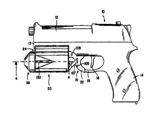
Referring first to FIGs 1 and 2, a lethal semi-automatic pistol 10 is
illustrated with a non-lethal
apparatus 20 attached thereto. Conventional pistol 10 generally includes a
barrel portion 12, a
handle portion 14, a trigger 16, and a trigger guard 18. Trigger guard 18 has
a forward portion
19 which is retained within a rear mounting portion 22 of apparatus 20.
Apparatus 20 also has
a seat portion 24 which receives and removably engages a lower side 13 of
barrel 12.
It will be appreciated that apparatus 20 is generally oriented in parallel
alignment with barrel
portion 12. Apparatus 20 has a housing unit 26 which receives a chemical
dispensing canister 28
containing a debilitating chemical substance under pressure. The substance,
such as pepper spray
or mace, in cannister 28 is mounted within housing unit 26, such that
discharge of the debilitating
substance will occur in parallel forward direction along the barrel 12.
Cannister 28 has a distal end 30, and a proximal end 31 with an actuator
button 32 located
thereon. A nozzle tube 34 emanates from said actuator button 32 and is in
communication with
cannister 28. Cannister 28 is removably contained within housing unit 26 by a
removably
connecting cap portion 36 and a rear wall 38 of apparatus 20.
Now referring to FIGs 2,3, and 4, cap portion 36 has an aperture 40 which
receives nozzle
tube 34, and an actuator ridge 42 which contacts with actuator button 32. A
canister ridge 44 is
located behind actuator ridge 42 and contacts proximal end 31 of cannister 28.
The constant
communication between canister ridge 44 and proximal end 31 not only helps
stabilize canister
28 within housing unit 26, but it also prevents unintentional articulation of
the actuator button 32
with actuator ridge 42. Distal to and perpendicular to canister ridge 44, cap
portion 36 has a
threaded wall 48 which engages a threaded portion 50 on apparatus 20, thereby
removably, yet
. securely, attaching cap portion 36 to apparatus 20.
SUBSTITUTE SHEET (RULE26)
CA 02286061 1999-10-13
WO 99/41563 PCT/US99/03060
_g_
Now referring to FIGS 5, SA, 5B, 6, 6A, and 6B, a right half 52 and a left
half 60 of apparatus
20 is more clearly illustrated. Half 52 and 60 each forms one half of housing
unit 26 and one half
of rear mounting portion 22. Right half 52 has a top ridge 54 and a bottom
ridge 56 which are
inserted into a top cavity 62 and a bottom cavity 64, respectively, of left
half 60. Right half 52
has a top protrusion 57 and a bottom protrusion 58 which are inserted into a
top indentation 66
and a bottom indentation 68, respectively, of left half 60. Right half 52 has
a rear prominence 59
which is received within a rear pit 70 of left half 60. The aforementioned
multiple
interconnections maintain both halves 52 and 60 of apparatus 20 in a stable
position.
Half 52 and 60 each forms one half of rear wall 38 which abuts distal end 30
of canister 28.
The rear wall 38 of both halves 52 and 60 have an inclined portion 72 and 74
respectively,
whereby when both halves 52 and 60 are joined, inclined portions 72 and 74
define an orifice 76.
Right inclined portion 72 has a right axial cavity 78, and left inclined
portion 74 has a left axial
cavity 80. Above orifice 76, rear wall 38 has attached thereto a right
mounting arm 82 and a left
mounting arm 84 which are curved to accommodate forward portion 19 of trigger
guard 18.
Both mounting arms 82 and 84 have a plurality of honey comb structures 86 to
produce rigidity
and strength in said arms 82 and 84. Right arm 82 has a first hump 88 and a
second hump 90
which are inserted into a first bore 92 and a second bore 94 of left arm 84
respectively, to supply
stability when both arms 82 and 84 are connected.
Now also referring to FIG 7, in addition to FIGs S, SA, SB, 6, 6A, 6B, a right
outer wall 96
extends from right arm 82 and a left outer wall 98 extends from left arm 84.
Right outer wall 96
defines a right retaining wall 100 and left outer wall 98 defines a left
retaining wall 102, where
said retaining wall 100 and 102 are perpendicular to said respective outer
walls 96 and 98. Said
retaining walls 100 and 102 are also curved to accommodate forward portion 19
of trigger guard
18 Whereby, when right half 52 and left half 60 are joined, arms 82 and 84,
outer walls 96 and
98, and retaining wails 100 and 102 form a chamber 104, said chamber 104
securely enclosing
forward portion 19 of trigger guard 18. To firmly, yet removably, enclose
trigger guard 18 within
chamber 104, at least an attaching hale 105 may traverse arms 82 and 84 and be
adapted to
receive a binding mechanism such as a screw or a bolt.
SUBSTITUTE SHEET (RULE 26)
CA 02286061 1999-10-13
WO 99/41563 PC'T/US99/03060
-10-
Seat portion 24, which attaches apparatus 20 to lower side 13 of barrel
portion 12, is formed
by a right curved wall 106 attached to a top of right half 52 and a left
curved wall 1 O8 attached
to a top of left half 60, whereby, when halves 52 and 60 are connected, a
valley is formed to
receive barrel portion 12.
Now referring to FIGS 2,7,8, and 8A in order to decrease an amount of force
needed to
actuate non lethal apparatus 20, an actuating lever 110 is utilized in
accordance with the physical
concept of torque, wherein a lever rotating along an axis produces torque
consistent with the
formula t =Fd. Wherein, z represents the torque generated at a reference axis,
F represents the
force applied, and d represents the distance from the axis at which the force
is applied. Thereby,
with a greater distance d, the force needed is decreased.
Actuating lever 110 has an axial rod I 12 having a right end 114 and a left
end 116, said ends
114 and 116 are received within right axial cavity 78 and left axial cavity 80
respectively, without
restricting axial movement. A bar 118 perpendicularly attaches to axial rod
112 at one end, and
bar I 18 perpendicularly attaches to a boom 120 at an opposing end. A
forwardly oriented curved
projection 122 is attached to boom 120 and bar I 18 such that projection 122
juts out of the plane
of attachment of boom 120 and bar 118. Projection 122 is inserted into orifice
76 on rear wall
38 of apparatus 20 and is in contact with distal end 30 of cannister 28. A
right shaft 124 and a
left shaft 126 attach to boom 120 at opposing ends thereof. Boom 120, and
shafts 124 and 126
saddle mounting arms 82 and 84 and are maintained in a firing position by at
least a stopper ridge
127 on either mounting arm 82 or 84. When disengaging apparatus 20, shafts 124
and 126 may
be pulled over stopper ridge 127, thus disengaging actuating lever 110.
Shafts 124 and I26 are substantially in parallel alignment with bar 118 and
thereby increase
the distance d in the formula r-Fd. A right force application pad l28 and a
left force application
pad 130 attach to shafts 124 and 126 respectively. Whereby, an application of
force to either pad
128 or 130 causes forward rotation of axial rod I 12, thus imparting force
onto projection 122,
which pushes on distal end 30 of canister 28, which in turn engages actuator
button 32, thereby
releasing a debilitating substance through nozzle tube 34.
Non-lethal apparatus 20 may be constructed of any substantially rigid
substance such as, but
SUBSTITUTE SHEET (RULE 26)
CA 02286061 1999-10-13
WO 99/41563 PCTNS99/03060
-11-
not limited to, plastics, metals, or wood. Apparatus 20 may be transparent or
have a viewing
window 132 to determine the contents of chemical dispensing canister 28.
While the invention herein disclosed has been described by means of specific
embodiment and
application thereoty numerous modifications, and variations could be made
thereto by those skilled
in the art without departing from the spirit and scope of the present
invention. Accordingly, the
scope of the invention should be determined not by the embodiments
illustrated, but by the
appended claims and their Legal equivalent.
SUBSTITUTE SHEET (RULE 26)